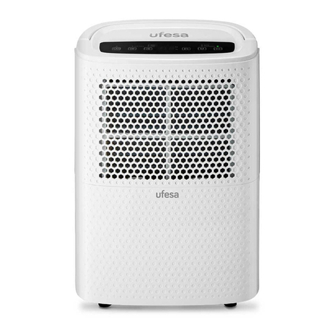
Deltech SPX FLOW HG Series User manual

HG Series
Refrigerated Type Compressed Air Dryers
Models: HG25, HG35, HG50
FORM NO.: 8610.483.7
REVISION: 10/2015 READ AND UNDERSTAND THIS MANUAL PRIOR TO OPERATING OR SERVICING THIS PRODUCT.
INSTRUCTION MANUAL

2
GENERAL SAFETY INFORMATION
1. PRESSURIZED DEVICES:
This equipment is a pressure containing
device.
• Donotexceedmaximumoperating
pressure as shown on equipment
serial number tag.
• Makesureequipmentisdepressurizedbeforeworking
onordisassemblingitforservice.
2. ELECTRICAL:
This equipment requires electricity to
operate.
• Installequipmentin compliancewith
all applicable electrical codes.
• Standard equipment is supplied with electrical en-
closures not intended for installation in hazardous
environments.
• Disconnectpowersupplytoequipmentwhenperform-
inganyelectricalservicework.
3. BREATHING AIR:
• Airtreatedbythisequipmentmaynot
besuitableforbreathingwithoutfur-
ther purification.
Refer to applicable standards and
specicationsfortherequirementsfor
breathing quality air.
RECEIVING, MOVING, AND UNPACKING
A. RECEIVING
Thisshipmenthasbeenthoroughlychecked,packedand
inspectedbeforeleavingourplant.Itwasreceivedingood
conditionbythecarrierandwassoacknowledged.
CheckforVisibleLossorDamage.Ifthisshipmentshows
evidenceoflossordamageattimeofdeliverytoyou,in-
sistthatanotationofthislossordamagebemadeonthe
delivery receipt by the carrier’s agent.
B. UNPACKING
Checkforconcealedlossor damage. Whena shipment
has been delivered to you in apparent good order, but
concealed damage is found upon unpacking, notify the
carrier immediately and insist on his agent inspecting the
shipment. Concealed damage claims are not our respon-
sibilityasourtermsareF.O.B.pointofshipment.
C. MOVING
Inmovingortransportingdryer,donottipdryerontoits
side.
D. STORAGE
IMPORTANT: Do not store dryer in temperatures above
130°F (54.4°C).
Contents
GENERALSAFETYINFORMATION ..................................... 2
RECEIVING,MOVING,ANDUNPACKING ........................... 2
INSTALLATION ................................................................... 3
INSTRUMENTATION .......................................................... 4
DRAINVALVES ................................................................. 4
START-UP/OPERATION...................................................... 4
SHUTDOWN...................................................................... 4
MAINTENANCE................................................................. 5
FIELDSERVICEGUIDE....................................................... 6
ENGINEERINGDATA ......................................................... 7
ELECTRICALSCHEMATICS ................................................. 8
AIRANDREFRIGERANTFLOWSCHEMATICS..................... 9
REPLACEMENTPARTS...................................................... 10
WARRANTY ...................................................................... 11

3
Compressor
Oil Removal
Filter
Aftercooler Automatic Drain
Dryer
Separator Receiver
TYPICAL COMPRESSED AIR SYSTEM
INSTALLATION
Ambient Air Temperature
Locatethedryerindoorswheretheambientairtemperaturewill
bebetween40°Fand100°F.Intermittentoperationatambient
temperatures up to 113°F will not damage the dryer but may
result in a higher dew point or dryer shutdown due to high
refrigerantdischargepressure(seeFieldServiceGuide).
Donotoperateair-cooleddryersatambientairtemperatures
below40°F.Suchoperationmayresultinlowsuctionpressure,
causingfreeze-up.
Call your local distributor if prolonged operation at ambient
temperatures above 100°F or below 40°F is unavoidable.
Location and Clearance
Mountthedryeron a level base. Install the dryer in a clean,
well-ventilatedareatoreducefoulingofthecondensercoils
with dirt and dust.
Vaporsandcontaminantscorrosivetocopperandaluminum
mustnotbeintheareaofthedryeroraircompressorintake.
Allowatleast6inchesclearancefromthefrontandfromthe
condensercoilserviceaccess.Installthedryerwiththeframe
level.Anchorboltsarenotrequired.
System Arrangement
Liquidwaterintheinletairwilladverselyaffecttheperformance
ofthedryer.Installthedryerdownstreamofanaftercooleror
separatorsothatthetemperatureofthedryerinletairdoesnot
exceed120°Fandtheinletairdoesnotcontainanyliquidwater.
Mostcompressedairsystemsrequireltersforremovalofsolid
andliquidcontaminants.Whenanoil-removallterisused,it
shouldbeinstalleddownstreamoftherefrigerateddryer.The
dryer will remove some entrained dirt, extending the life of
the replaceable filter element. Outlet air temperature may be
10 to 30 degrees higher than inlet air temperature. This is nor-
mal.Consultyourdistributorifaloweroutletairtemperature
is required.
Piping and Connections
Pipingmustbefurnishedbytheuserunlessotherwisespeci-
ed.Connectionsandttingsmustberatedforthemaximum
operating pressure given on the dryer data plate and must be
inaccordancewithapplicablecodes.Supportallpiping;donot
allow the weight of any piping to stress the dryer or lters.
Inletandoutletshutoffvalvesandabypassvalvearerecom-
mended.Pipingshouldbeatleastthesizeoftheinletandoutlet
connectionstominimizepressuredropintheairsystem.See
EngineeringDatasectionfordryerinletandoutletconnections.
Removing Condensate
Aseparatorwithanautomaticdrainvalveissuppliedwitheach
dryer. The user must install a separate discharge line at the drain
connectiontocarryoffcondensatetoanenvironmentallyap-
provedcondensatecollection/disposalsystem.Securelyanchor
drain line to prevent whipping.
Ifcloggingoftheautomaticdrainisaproblem,installaparticu-
latelterbeforethedryertokeepsolidparticlesfromentering
the dryer. Contact your local distributor for the appropriate
particulate filter.
Electrical Connections (See Figure 1)
Dryer is designed to operate on the voltage, phase and fre-
quencylistedontheserialnumbertag.Referencetagpriorto
makingelectricalconnection.Dryersaresuppliedwithacord
andplug.Installinreceptacleofpropervoltage.
Operation of dryers with improper line voltage
constitutesabuseandcouldaffectthedryerwarranty.

4
INSTRUMENTATION
ON/OFF Switch
ThedryerisequippedwithanON/OFFswitchonthefrontpanel.
Alightsignalswhenthedryerison.
Color Indicator
Alldryersareequippedwithacolorindicatorwhichindicates
dryerconditionsasfollows:
Itisnormalfortheindicatorcolortobeintheredzonewhen
thedryerisrstturnedonandthenmovetothegreenzone
whenthedryerreachesitsnormaloperatingtemperature.Ifthis
indicatorisintheredzoneduringnormaloperation,turnthe
dryerofftoavoidcompressordamage.RefertotheFieldService
Guideforadditionalinformation,orcallyourlocaldistributor.
DRAIN VALVES
Anelectronicdrainvalveissuppliedtoautomaticallydischarge
condensatefromthedryer.Thedrainvalveanditscontrolsare
accessiblefromtherearofthedryer.Theelectronicdrainvalve
hastwoindicatorsandatestbuttontohelpverifyoperation.
Pushingthetestbuttoncausesthedrainporttoclickopen.If
eitherindicatorfailstoturnonatthepropertime,refertothe
maintenancesectionofthismanual.Drainvalveoperationis
controlled by an electronic timer. The drain opening can be
setfrom0.5secto10sec.Thedraincyclecanbesetfrom0.5
min to 45 min.
Drain Valve Adjustment
Tominimizeairlosses,thedraintimershouldbeadjustedto
openthedrainportjustlongenoughtodischargeaccumulated
condensate.Setthetimersothatonlyairdischargesattheend
oftheopenperiod.
Recommended Drain Settings
Time
Model Open(Sec) Closed(Min)
HG25 2 10
HG35 2 10
HG50 2 10
NOTE:Ifliquiddischargesastheportisclosing,setthetimerfora
shortercycleoralongeropening.Theamountofcondensatewill
vary as ambient conditions and inlet flow rates change.
START-UP/OPERATION
Followtheprocedurebelowtostartyourdryer.Failuretofollow
theprescribedstart-upprocedurewillinvalidatethewarranty.If
problemsariseduringstart-up,callyourdistributor.
RefertoSerialNumberTagfordryeroperating
capacity.Donotexceedrecommendedcapacity.
Drainconnectionsmustbemadebeforethedryercanbeop-
erated.Thedryersarefullyautomaticandrequirenoauxiliary
controls.
1. Connectinletandoutletlinestothedryer.Referencedryer
indentationsandinstructiontagforappropriateinletand
outlet connections.
2. Route drain connections to a condensate separator or ap-
proved collection point.
3. Turntheon/offswitchtoon.Doublecheckconnections.
4. Afterthedryerhasbeenrunningfor30minutes:
a. Check that on/off lighted switch is glowing. If light
isnotglowing,unplugunitandrefertoFieldService
Guideforadditionalinformationorcallyourlocaldis-
tributor.
b. ChecktheColorIndicator.IftheIndicatorisinthered
zone,unplugthedryer.RefertotheFieldServiceGuide
foradditionalinformation,orcallyourlocaldistributor.
c. Conrmthatcondensateisdischargingfromthedrain.
This can only be done when there is air flow through
the dryer.
Reference Serial Number Tag for appropriate
powerrequirement/connectionrating.Makeotherdryercon-
nections prior to connecting power source.
Thedryer is designedto runcontinuously.Let the dryerrun
evenwhenthedemandforcompressedairisinterrupted;the
dryerwillnotfreezeup.
Operating Check Points
1. Powerlightison,lightisilluminated.
2. Condensate is discharging properly.
3. ColorIndicatorisintheGreenZone.
SHUTDOWN
Whenthedryermustbeshutdownformaintenanceorother
reasons,usethefollowingprocedure:
1. Turnthepoweron/offswitchtooff.
2. Disconnectthemainpowersupply.
Ifmechanicalrepairsaretobemadeorserviceisperformed,
venttheinternalpressureofthedryertoatmosphericpressure.
Restart the dryer according to the start-up instructions.
Disconnectpowersupplyanddepressurizedryer
beforeservicing.Dismantlingorworkingonanycomponentof
the compressed air system under pressure may cause equip-
mentfailureandseriouspersonalinjury.

5
MAINTENANCE
The dryers require little maintenance for satisfactory opera-
tion.Gooddryerperformancecanbeexpectedifthefollowing
routinemaintenancestepsaretaken.
Disconnectpowersupplyanddepressurizedryer
beforeperforminganymaintenance.
General
Forcontinuedgoodperformanceofyourrefrigerateddryer,
allrefrigerationsystemmaintenanceshouldbeperformedby
acompetentrefrigerationmechanic.
NOTE:Beforecorrectivemaintenanceisdoneduringthewar-
rantyperiod,callyourlocaldistributorandproceedaccordingto
instructions.Refertothewarrantyforlimitsofyourcoverage.
Daily Maintenance
Checktheseparatorforcondensatedischarge.Ifnodischarge
isevident,depressurizeandperformthefollowing:
1. ElectricDrain-Cleanstrainerand/orclean/replacesolenoid
valve.
Monthly Maintenance
Inspectthecondensercoils.Removeaccumulateddustanddirt
withasoftbrushorwithairfromanOSHAapprovedcompressed
airnozzlethatlimitsthedischargepressureto30psig.
Electronic Drain Valve Disassembly and Servicing
Donotdisassembledrainvalvetimerorattempt
torepairelectricalparts.Replacetimerifdefective.
Thedrainvalvedischargecondensatethroughafull-portdrain
opening. The valve body may need to be cleaned under condi-
tionsofgrossparticulatecontamination.
To disassemble the drain valve body for cleaning and other
maintenance:
1. Turnpowerswitchoff.
2. Disconnectmainpowersupplytodryer.
3. Depressurizeunit.
4. LockoutandtagpowersupplyinaccordancewithOSHA
requirements.
Ifpowersupplyisnotconnectedandunitisnot
depressurizedbeforedisassembly,seriouspersonalinjuryand
valve damage may result.
5. Removescrewandwasherfromfrontofthedrainvalve.
6. Removethepowersupplyconnectorandgasket(withthe
timerassemblyifattached)fromthesolenoidcoilhousing.
Donotdamageorlosethegasket.
7. Remove coil xing nut and spring washer from top of
solenoid coil housing.
8. Liftsolenoidcoilhousingoffsolenoidcoreinvalvebody.
9. Unscrewsolenoidcorefromvalvebody.
Oncethedrainvalveisdisassembled,thefollowingmaintenance
canbeperformed.
1. Inspect internal parts of valve body; clean or replace as
required.
NOTE: Replace solenoid valve if component damage is
observed.
2. Removedebrisfromvalvebody.
3. Wipesolenoidcorecomponentswithacleanclothorblow
outdebriswithcompressedairfromanOSHA-approvedair
nozzlethatlimitsitsdischargepressureto30psig.
4. Checkthattheplungerassemblyiscleanandmovesfreely
in housing.
5. Iftimerisattachedtovalvebody,checkelectricalcontinuity
across timer assembly.
To reassemble the drain valve, reverse the sequence of
theprecedingsteps.Afterthedrainvalveisreassembled,
connectthemainpowersupplytothedryer.Whenthe
dryerisreturnedtoservice,checkthedrainvalveforairor
condensateleaks;tightenconnectionsasrequiredtocor-
rectleaks.Checkthedraincycle;adjustthetimeraccording
totheprocedureinthedrainvalveadjustmentsection.
Returns to Manufacturer
Ifthedryeroracomponentofthedryermustbereturnedto
themanufacturer,rstcallyourlocaldistributorforareturn
authorizationnumberandshippingaddress.Yourdistributor
willinformyouwhetherthedryeroronlyacomponentmustbe
returned.Markthepackagewiththereturnauthorizationnum-
berandshipfreightprepaidasdirectedbyyourlocaldistributor.

6
FIELD SERVICE GUIDE
Problemsmostfrequentlyencounteredwithrefrigerateddry-
ersarewaterdownstreamofthedryerandexcessivepressure
drop.Mostcausescanbeidentiedandremediedbyfollowing
this guide.
Closed refrigeration systems are potentially
dangerous. Work on the refrigeration system must be done
only by a competent refrigeration mechanic. Do not release
uorocarbonrefrigerantstotheatmosphere.Allrefrigerants
mustberecoveredperEPArequirements.Donotsmokewhen
arefrigerationleakissuspected.Burningmaterialsmaydecom-
poserefrigerants,formingatoxicgasoracidsthatmaycause
serious injury and property damage. Before dismantling any
partofthedryerorcompressedairsystem,completelyvent
the internal pressure to the atmosphere.
PROBLEM SYMPTOM POSSIBLE CAUSE REMEDY
Water Downstream of
Dryer
Refrigerantcompressornot
running.
Leakinrefrigerationsystem. Contact your local distributor.
Compressor overheated. Turndryeroff,wait30minutes;turndryeron.
(Motorthermostatself-starting)
Compressor burned out. Contact your local distributor.
Nocondensatedischargingfrom
dryer.
Failureofdrain. Dismantleandcleanstrainer.Repairorreplace
solenoid valve.
Dryerinletairtemperaturetoo
high.
Aftercoolermalfunction. Checkaftercoolerdischargetemperatureand
reducetodryerdesigncondition(120°Fmax)
Excessive Pressure
Drop Across Dryer
Lowoutletpressure. Dryerundersized(mayalsocause
waterdownstreamofdryer)
Checkairowanddryercapacity.Reduceairowor
resizeandreplacedryer.
Dryericingup.(checkatseparator) Contact your local distributor.
Color Indicator Out of
Green Zone
Indicatorinredzone. Inletairtemperaturetoohigh. Reduceaftercoolerdischargetemperaturetodesign
conditions(SeeEngineeringData).
Condenserfouledorclogged. Clean or replace condenser.
Inletairtemperaturetoohigh. Reduceaftercoolerdischargetemperaturetodesign
conditions.(SeeEngineeringData)
Highambienttemperature. Ventilatearea.
Improperadjustmentofexpansion
valve.
Removecapfromtheexpansionvalveandturnthe
screwuntiltheindicatorisinthegreenzone.
Indicatorinbluezone. Improperadjustmentofexpansion
valve.
Adjusttheexpansionvalveuntiltheindicatorisin
thegreenzone.
Lowambienttemperature. Increaseambienttemperaturetodesignconditions.

7
ENGINEERING DATA
MODEL HG25 HG35 HG50
SPECIFICATIONS
Rated Capacitya-(scfm) 25 35 50
Inlet/OutletConnections-(inches) 3/4 3/4 3/4
Dimensions
Height-(inches) 22.2 22.2 22.2
Length-(inches) 15.5 15.5 19.7
Width-(inches) 14.5 14.5 19.7
PowerSupply-(V/Ph/Hz) 115/1/60 115/1/60 115/1/60
RefrigerantCompressorRating-(hp) 1/4 1/4 1/3
InputPower-(kW) 0.47 0.47 0.63
RefrigerantTypebR-134a R-134a R-134a
aRating conditionsare100°Finlettemperature,100psiginletpressure,100%inletrelativehumidity,100°Fambienttemperature@60Hz.PerCAGIADF-100.
bRefertodryerdataplateforrefrigerantcharge.
MODEL HG25, HG35, HG50
MINIMUM - MAXIMUM OPERATING CONDITIONS
Min.-Max.InletAirPressure(compressedairatinlettodryer) 30 - 250 psig
Min.-Max.InletAirTemperature(compressedairatinlettodryer) 40°F - 120°F
Min.-Max.AmbientTemperature 40°F - 110°F
NOTE:Continuousoperationintheabovemaximumandminimumoperationconditionsisnotallowable.

8
ELECTRICAL SCHEMATICS
ON/OFF SWITCH
WITH RUNNING LAMP
R
25
6
PTC STARTER
SM
COMP.
1PH
C
OVERLOAD
PROTECTOR
DRAIN SOL.
VALVE TIMER
T
Figure 1
25-50 scfm models

9
AIR AND REFRIGERANT FLOW SCHEMATICS
Figure 2
25-50 scfm models
HEAT EXCHANGER
REHEATER
AIR OUTLET
AUX. CONDENSER
CONDENSER
REF. COMPRESSOR
ELECTRONIC
DRAIN
VALVE
LIQUID RECEIVER
FILTER DRYER
CONSTANT PRESSURE
EXPANSION VALVE
DRAIN OUTLET
COLOR INDICATOR
C.I.
CHILLER
EVAPORATOR
AIR INLET

10
REPLACEMENT PARTS
Item HG25 HG35 HG50
HeatExchanger 7426019 7426019 7426020
RefrigerantCompressor 3146980 3146980 3149274
Filter/SeperatorDrainValve 3142801 3142801 3142801
Condenser 3163333 3163333 3163333
On/OffSwitch 3245021 3245021 3245021
ConstantPress.ExpansionValve 3161268 3161268 3161268
LiquidReceiver/FilterDryer 1283369 1283369 1283369
ElectronicDrainValve 3149293 3149293 3149293
ColorIndicator 7426023 7426023 7426023
MaintenanceKits RDJMK2 RDJMK2 RDJMK2
Phone: 724-745-8647
FAX: 724-745-4967
Email: deltech.americas.am@spxow.com
Web: www.spxow.com/deltech

AUTHORIZATION FROM THE SERVICE DEPARTMENT IS NECESSARY BEFORE MATERIAL IS
RETURNED TO THE FACTORY OR IN-WARRANTY REPAIRS ARE MADE.
WARRANTY
Themanufacturerwarrantstheproductmanufacturedbyit,whenproperlyinstalled,operated,applied,andmaintainedinaccordancewithproce-
duresandrecommendationsoutlinedinmanufacturer’sinstructionmanuals,tobefreefromdefectsinmaterialorworkmanshipforaperiodas
speciedbelow,providedsuchdefectisdiscoveredandbroughttothemanufacturer’sattentionwithintheaforesaidwarrantyperiod.
Themanufacturerwillrepairorreplaceanyproductorpartdeterminedtobedefectivebythemanufacturerwithinthewarrantyperiod,provided
suchdefectoccurredinnormalserviceandnotasaresultofmisuse,abuse,neglectoraccident.Normalmaintenanceitemsrequiringroutinereplace-
mentarenotwarranted.Thewarrantycoverspartsandlaborforthewarrantyperiodunlessotherwisespecied.Repairorreplacementshallbemade
atthefactoryortheinstallationsite,atthesoleoptionofthemanufacturer.Anyserviceperformedontheproductbyanyoneotherthanthemanu-
facturermustrstbeauthorizedbythemanufacturer.
Unauthorizedservicevoidsthewarrantyandanyresultingchargeorsubsequentclaimwillnotbepaid.Productsrepairedorreplacedunderwarranty
shallbewarrantedfortheunexpiredportionofthewarrantyapplyingtotheoriginalproduct.
Theforegoingistheexclusiveremedyofanybuyerofthemanufacturer’sproduct.Themaximumdamagesliabilityofthemanufactureristheoriginal
purchasepriceoftheproductorpart.
THEFOREGOINGWARRANTYISEXCLUSIVEANDINLIEUOFALLOTHERWARRANTIES,WHETHERWRITTEN,ORAL,ORSTATUTORY,ANDISEXPRESSLYINLIEU
OFTHEIMPLIEDWARRANTYOFMERCHANTABILITYANDTHEIMPLIEDWARRANTYOFFITNESSFORAPARTICULARPURPOSE.THEMANUFACTURERSHALL
NOTBELIABLEFORLOSSORDAMAGEBYREASONOFSTRICTLIABILITYINTORTORITSNEGLIGENCEINWHATEVERMANNERINCLUDINGDESIGN,MANUFAC-
TUREORINSPECTIONOFTHEEQUIPMENTORITSFAILURETODISCOVER,REPORT,REPAIR,ORMODIFYLATENTDEFECTSINHERENTTHEREIN.
THEMANUFACTURER,HISREPRESENTATIVEORDISTRIBUTORSHALLNOTBELIABLEFORLOSSOFUSEOFTHEPRODUCTOROTHERINCIDENTALORCONSE-
QUENTIALCOSTS,EXPENSES,ORDAMAGESINCURREDBYTHEBUYER,WHETHERARISINGFROMBREACHOFWARRANTY,NEGLIGENCEORSTRICTLIABILITY
INTORT.
Themanufacturerdoesnotwarrantanyproduct,part,material,component,oraccessorymanufacturedbyothersandsoldorsuppliedinconnection
withthesaleofmanufacturer’sproducts.
Warranty Period
Partsandlaborfortwo(2)yearsfromthedateofshipmentfromthefactory;heatexchangersarecovered(partsonly)foranadditionalthree(3)
years(totalofve[5]).Onunitsthatmanufacturerrequestsbereturnedtothefactory,aonetimeremoval/reinstallationlaborallowanceasnotedin
theServiceWarrantyPoliciesandProceduresHandbookwillapply.Freighttothefactoryfromtheinstallationsiteandtotheinstallationsitefromthe
factorywillbepaidbythemanufacturer;meansoftransportationtobespeciedbymanufacturer.
SERVICE DEPARTMENT: (724) 746-1100

SPX FLOW, INC.
4647 S.W. 40th Avenue
Ocala, Florida 34474-5788 U.S.A.
P: (724) 745-8647
F: (724) 745-4967
E: deltech.americas@spxflow.com
www. spxflow.com/deltech
Improvements and research are continuous at SPX FLOW, Inc.
Specifications may change without notice.
ISSUED 10/2015 Form No.: 8610.483.7 Revision: A
COPYRIGHT ©2015 SPX FLOW, Inc.
HG Series
Refrigerated Type Compressed Air Dryers
Models: HG25, HG35, HG50
This manual suits for next models
3
Table of contents
Other Deltech Dehumidifier manuals
