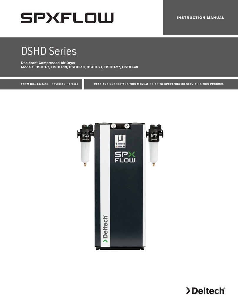
Deltech SPX FLOW User manual

HGEN Series
Refrigerated Type Compressed Air Dryers
Models: HGEN600, HGEN800, HGEN1000, HGEN1200
FORM NO.: 7426448 REVISION: 10/2018 READ AND UNDERSTAND THIS MANUAL PRIOR TO OPERATING OR SERVICING THIS PRODUCT.
INSTRUCTION MANUAL
MCGUIRE AIR COMPRESSORS INC
1-888-229-9999
MCGUIRE AIR COMPRESSORS INC
1-888-229-9999

Contents
GENERAL SAFETY INFORMATION ........................................................................... 1
RECEIVING, MOVING, AND UNPACKING ................................................................. 1
INSTALLATION......................................................................................................... 2
INSTRUMENTATION ................................................................................................ 3
START-UP/OPERATION............................................................................................ 4
SHUTDOWN............................................................................................................ 4
MAINTENANCE....................................................................................................... 5
FIELD SERVICE GUIDE............................................................................................. 6
SPECIFICATIONS
ENGINEERING DATA TABLE.................................................................................. 7
AIR-COOLED UNITS
General Arrangement Drawings
Model HGEN600A ........................................................................................ 8
Model HGEN800A ........................................................................................ 9
Models HGEN1000A through HGEN1200A.................................................. 10
Electrical Schematics
Model HGEN600A ........................................................................................ 11
Models HGEN800A through HGEN1200A.................................................... 12
Air and Refrigerant Flow Schematics
Model HGEN600A ........................................................................................ 13
Models HGEN800A through HGEN1200A.................................................... 14
WATER-COOLED UNITS
General Arrangement Drawings
Model HGEN600W ....................................................................................... 15
Model HGEN800W ....................................................................................... 16
Models HGEN1000W through HGEN1200W................................................ 17
Electrical Schematics
Model HGEN600W ....................................................................................... 18
Models HGEN800W through HGEN1200W.................................................. 19
Air and Refrigerant Flow Schematics
Model HGEN600W ....................................................................................... 20
Models HGEN800W through HGEN1200W.................................................. 21
REPLACEMENT PARTS............................................................................................ 22
NOTES.................................................................................................................... 23
WARRANTY ............................................................................................................ 25
MCGUIRE AIR COMPRESSORS INC
1-888-229-9999
MCGUIRE AIR COMPRESSORS INC
1-888-229-9999

1
GENERAL SAFETY INFORMATION
1. PRESSURIZED DEVICES:
This equipment is a pressure containing
device.
• Do not exceed maximum operating
pressure as shown on equipment
serial number tag.
• Make sure equipment is depressurized before working
on or disassembling it for service.
2. ELECTRICAL:
This equipment requires electricity to
operate.
• Install equipment in compliance with
all applicable electrical codes.
• Standard equipment is supplied with electrical en-
closures not intended for installation in hazardous
environments.
• Disconnect power supply to equipment when perform-
ing any electrical service work.
3. BREATHING AIR:
• Air treated by this equipment may not
be suitable for breathing without fur-
ther purification.
Refer to applicable standards and
specifications for the requirements for
breathing quality air.
RECEIVING, MOVING, AND UNPACKING
A. RECEIVING
This shipment has been thoroughly checked, packed and
inspected before leaving our plant. It was received in good
condition by the carrier and was so acknowledged.
To assure proper transport, tilt indicators are attached to
the shipping container before it leaves the factory. Check
these before accepting unit from carrier's agent.
Check for Visible Loss or Damage. If this shipment shows
evidence of loss or damage at time of delivery to you, in-
sist that a notation of this loss or damage be made on the
delivery receipt by the carrier’s agent.
B. UNPACKING
Check for concealed loss or damage. When a shipment
has been delivered to you in apparent good order, but
concealed damage is found upon unpacking, notify the
carrier immediately and insist on his agent inspecting the
shipment. Concealed damage claims are not our responsi-
bility as our terms are F.O.B. point of shipment.
C. MOVING
In moving or transporting dryer, do not tip dryer onto its
side.
D. STORAGE
Dryer should not be stored outside (either
packed or unpacked) or exposed to the weather. Damage
to electrical and control components may result.
IMPORTANT: WATER-COOLED UNITS - If unit is shut down in
below freezing temperatures, the water-cooled condenser
may freeze and cause permanent damage. Condenser must
be drained when unit is shut down.
IMPORTANT: Do not store dryer in temperatures above
130°F (54.4°C).
MCGUIRE AIR COMPRESSORS INC
1-888-229-9999
MCGUIRE AIR COMPRESSORS INC
1-888-229-9999

2
Compressor
Oil Removal
Filter
Aftercooler Automatic Drain
Dryer
Separator Receiver
TYPICAL COMPRESSED AIR SYSTEM
INSTALLATION
Ambient Air Temperature
Locate the dryer indoors where the ambient air temperature
will be between 40°F (4°C) and 110°F (43°C). Intermittent op-
eration at ambient temperatures up to 113°F (45°C) will not
damage the dryer but may result in a higher dew point or dryer
shutdown due to high refrigerant discharge pressure (see Field
Service Guide).
Do not operate dryers at ambient air temperatures below 40°F
(4°C). Such operation may result in low suction pressure, caus-
ing freeze-up.
Location and Clearance
Mount the dryer on a level solid surface. Holes are provided in
the dryer base to permanently mount the dryer to the floor. If
the base vibrates, bolt the unit down using vibration dampeners.
Allow at least 36 inches (914 mm) clearance on the sides and
the front of the dryer for cooling airflow and for service access.
System Arrangement
Liquid water in the inlet air will adversely affect the performance
of the dryer. Install the dryer downstream of an aftercooler or
separator so that the temperature of the dryer inlet air does
not exceed 120°F (49°C) and the inlet air does not contain any
liquid water.
If the compressed airflow is relatively constant and does not
exceed the dryer flow rating, it is recommended that the dryer
be located downstream of the receiver tank. If the nature of the
application is such that the air demand regularly exceeds the
dryer flow rating, it is recommended that the dryer be located
upstream of the receiver.
For safety and convenience, install inlet and outlet shutoff valves
and depressurization valves. These valves allow the dryer to be
isolated and depressurized for servicing. Bypass piping may
be installed around the dryer for uninterrupted airflow when
the dryer is serviced. If the compressed air operation cannot
tolerate undried air for short periods, install a second dryer in
the bypass line.
Compressed air systems commonly require filters to remove
compressor oils, particulates, condensed liquids and other
contaminants. When an oil-removal filter is used, it should be
installed downstream of the refrigerated dryer. At this location,
the life of the replaceable filter element is prolonged since
some of the entrained oil is removed by the dryer and drained
through the separator.
Piping and Connections
Piping must be furnished by the user unless otherwise speci-
fied. Connections and fittings must be rated for the maximum
operating pressure given on the dryer data plate and must be
in accordance with applicable codes. Support all piping; do not
allow the weight of any piping to stress the dryer or filter con-
nections. Piping should be at least the size of the inlet and outlet
connections to minimize pressure drop in the air system. See
Engineering Data section for dryer inlet and outlet connections
1. Air Inlet - Connect compressed air line from air source to
air inlet.
Refer to Serial Number Tag for maximum working
pressure. Do not exceed dryer's Maximum Working Pressure.
NOTE: Install air dryer in air system at highest pressure possible
(e.g. before pressure reducing valves).
NOTE: Install dryer at coolest compressed air temperature
possible. Maximum inlet compressed air temperature: 120°F
(49°C). If inlet air exceeds this temperature, precool the air with
an aftercooler.
2. Air Outlet - Connect air outlet to downstream air lines.
3. Bypass Piping - If servicing the dryer with interrupting the
air supply is desired, piping should include inlet and outlet
valves and an air bypass valve.
4. Water-cooled models - cooling water inlet and outlet.
a) Connect cooling water supply to cooling water inlet.
b) Connect cooling water return line to cooling water
outlet connection.
NOTE: Strainer and water regulating valve are supplied on water-
cooled models. Also, it is recommended to add water inlet/
outlet temperature and pressure gauges to the water piping.
Removing Condensate
Condensate must be drained from the dryer to prevent re-
entrainment. The dryers are equipped with automatic drain
valves and internal drain hoses up to the drain connections on
the dryer cabinets. The user must install a separate discharge
line at the drain connection to carry off condensate to an envi-
ronmentally approved condensate collection/disposal system.
Piping or copper tubing 1/2 inch or larger is recommended
for condensate discharge lines. Install the drain lines so that
condensate can be seen as it drains.
Electrical Connections
The dryers are constructed according to NEMA Type 1 electrical
standards. Field wiring must comply with local and national fire,
safety and electrical codes. Installation must be in accordance
with the National Electrical Code.
IMPORTANT: Use copper supply wires only.
1. Dryer is designed to operate on the voltage, phase, and
frequency listed on the dryer serial number tag.
2. Electrical entry is through a hole in the back of the cabinet.
Route wires through the bottom of the electrical enclosure.
Connect power source to the terminal strip in the electrical
enclosure as shown on the electrical schematics included
in this manual.
MCGUIRE AIR COMPRESSORS INC
1-888-229-9999
MCGUIRE AIR COMPRESSORS INC
1-888-229-9999

3
NOTE: Refrigeration condensing unit is designed to run con-
tinuously and should NOT be wired to cycle on/off with the air
compressor.
Operation of dryers with improper line volt-
age constitutes abuse and could affect the dryer war-
ranty.
INSTRUMENTATION
ON/OFF Switch
The dryer is equipped with an ON/OFF switch on the front panel.
A light signals when the dryer is on.
Dryer System Monitor (DSM)
The Dryer System Monitor (DSM) has LED type dew point tem-
perature indicator and operating time control for the electronic
drain valve. When the dryer is running normally, the green LED
will illuminate. If the red LED is illuminated, there is a need for
the dryer's operating condition to be checked. If all LEDs are
illuminated, the sensor for the dew point temperature indicator
has malfunctioned.
The automatic drain valve controls allow the period of drain
opening to be set from 1 second to 9 seconds and drain valve
closed time to be set from 0.5 minutes to 15 minutes. When the
Drain Push-to-Test button (5) is pushed for one (1) second, the
Drain LED (6) will illuminate and the drain port opens with a click.
Automatic Drain Valve
All models are equipped with an electronic drain valve that au-
tomatically discharges condensate from the dryer. Drain valve
operation is controlled by a drain valve timer. The drain opening
can be set from 0.5 seconds to 9 seconds. The drain cycle can
be set from 0.5 minutes to 15 minutes.
Drain valve adjustments are made on the Dryer System Monitor:
1. Press the Selection (4) and Enter (5) buttons at the same
time for 3 seconds, the On Time Setting Mode LED (3) will
start to blink, and the illuminated LED on the Dew Point
Temperature Indicator LED (2) will identify the factory set-
ting for "On Time". (See table)
2. Press and release the Selection button (4) to sequence from
left to right until reaching your selection. The red LED is
not used.
3. To store the "On Time", press the Enter button (5) and set
the "Off Time" using step 2.
4. To store the "Off Time", press the Enter button (5) again.
5. Exiting the Program will cause the Timer Drain to discharge
and begin a new cycle.
NOTE: Failure to perform step 3 within 10 seconds of complet-
ing step 2 will cause the unit to revert back to the previous
setting.
LED (2)
Position 1st 2nd 3rd 4th 5th 6th 7th 8th 9th
On
Time
(sec)
12345678
Continuous
(Drain Trap
Option)
Off
Time
(min)
0.5 1 2 3 5 7 9 10 15
173 4 10
928
5 6
Dryer System Monitor
1. On/Off Switch: Press the top of the switch (I) to turn
the dryer on. Press the bottom of the switch (O) to
turn the dryer off. When the dryer is on, the switch
is illuminated.
2. Dew Point Temperature Indicator: Main portion of
the graphic for the dew point temperature scale.
Green indicates low, red indicates high.
3. Compressor On Light / On Time Setting Mode: Dual
purpose LED indicating light. Illuminates as solid light
when compressor is ON. Blinks On and Off during
setup of the On Time Set Points for the Automatic
Drain Valve.
4. Selection Button: During set up of the Automatic
Drain Valve, when pressed, sequences from left to
right.
5. Drain Push-to-Test Button / Enter Button:
a) Drain Push-to-Test button. When the button is
pressed, the drain valve opens for the time corre-
sponding to the setting established during Drain
Valve setup.
b) Enter button. Stores the "On Time" and "off Time'
drain valve settings established during Drain Valve
setup
6. Drain LED / Off Time Setting Mode: Dual purpose LED
indicating light. Illuminates as solid light when Drain
is closed. Blinks On and Off during setup of the Off
Time Set Points for the Automatic Drain Valve.
7. This is a graphic symbol for the Air Dryer compres-
sor. It simply indicates that the switch is used to turn
the compressor (dryer) on and off.
8. Part of the graphic for the dew point temperature
scale. The snowflake indicates the low (cold) end of
the scale.
9. Part of the graphic for the dew point temperature
scale. The thermometer indicates the high (hot) end
of the scale.
10. This is a graphic symbol for the Drain Valve.
MCGUIRE AIR COMPRESSORS INC
1-888-229-9999
MCGUIRE AIR COMPRESSORS INC
1-888-229-9999

4
Electronic Drain Valve Adjustment
The automatic drain valve has been pre-programmed at the
factory for your specific HGEN Series dryer. Programming is
based upon a minimum of 100 psi saturated inlet air pressure
and maximum energy efficiency. Generally no adjustment to
the timer is necessary.
If water is present downstream of the dryer,
always verify that and condensate drains installed upstream
of the dryer are draining properly before attempting to adjust
the timer settings.
1. For minimum inlet air pressures that fall between column
values the setting for the lower pressure is recommended.
(i.e. select the 100 psi column values for 124 psi inlet pres-
sure.)
2. Where the dryer is consistently operating at less than
maximum capacity, it may be possible to alter the timer set
points to minimize air loss. Discretionary adjustments to the
dryer should only be made on a hot, humid day when the
maximum expected air load is flowing through the dryer.
Failure to do so may prevent the condensate from draining
completely when operating under peak load conditions.
Dryer Model
Inlet Pressure (psig)
75 100* 125 150 200 225
On Off On Off On Off On Off On Off On Off
(sec) (min) (sec) (min) (sec) (min) (sec) (min) (sec) (min) (sec) (min)
HGEN600 2 1 2 1 2 2 2 3 2 5 2 6
HGEN800 2 2 2 2 2 3 2 5 2 8 2 8
HGEN1000 2 2 2 2 2 3 2 4 2 6 2 8
HGEN1200 2 1 2 1 2 2 2 3 2 5 2 6
* Recommended and pre-programmed factory settings for each HGEN Series
model dryer.
Assumes dryer operates at ISO 7183 (Option A2) conditions: 100°F inlet air
temperature, 100 psig operating pressure, 100°F ambient air temperature and
10°F air-cooled after-cooler approach temperature.
START-UP/OPERATION
Follow the procedure below to start your dryer. Failure to follow
the prescribed start-up procedure will invalidate the warranty. If
problems arise during start-up, call your distributor.
Refer to Serial Number Tag for dryer operating
capacity. Do not exceed recommended capacity.
Drain connections must be made before the dryer can be op-
erated. The dryers are fully automatic and require no auxiliary
controls.
1. Turn the dryer ON/OFF switch to OFF.
2. Check that the main electrical supply voltage matches the
voltage specified on the dryer data plate.
3. Check proper connection and support of compressed air
lines to the dryer; check bypass valve system, if installed.
4. Energize Dryer: Turn disconnect switch to "ON" position.
Green dryer ON/OFF switch will illuminate.
Energize dryer for 24 hours before refrigera-
tion compressor is started! Never use the disconnect switch
to shutdown the dryer for an extended period of time
(except for repair). Failure to follow these instructions may
result in a non-warrantable compressor failure.
5. Ensure adequate ventilation for air-cooled dryers.
6. On water-cooled models, before starting dryer, begin cool-
ing water flow.
To start dryer:
1. Turn the power switch to ON. The refrigerant compressor
will turn on.
Dryer must be energize 24 hours before
starting refrigeration compressor.
2. Allow the dryer to run 15 minutes. Confirm that the tem-
perature indicators are in the green zone.
3. SLOWLY pressurize the dryer. The outlet valves of the dryer
should be closed to prevent flow through the dryer.
4. SLOWLY open the dryer outlet valves permitting flow
through the dryer.
5. Confirm that condensate is discharging from the drain valve
by pressing the "Push-to Test" button.
6. Check drain valve timing. See Automatic Drain Valve section
for drain valve adjustment procedure.
7. Confirm that the inlet air temperature, pressure and airflow
to the dryer meet the specified requirements (see Engi-
neering Data section).
8. Confirm that the condensate lines from the drain valve
discharge into a collection tank or an environmentally-
approved disposal system.
The dryer is designed to run continuously. Let the dryer run
even when the demand for compressed air is interrupted; the
dryer will not freeze up.
SHUTDOWN
When the dryer must be shutdown for maintenance or other
reasons, use the following procedure.
If electrical repairs must be made:
1. Turn off the power switch.
2. Disconnect the main power supply.
3. Lock out and tag the power supply in accordance with OSHA
requirements.
If mechanical repairs are to be made or service is performed,
vent the internal pressure of the dryer to atmospheric pressure.
Restart the dryer according to the start-up instructions.
Disconnect power supply and depressurize dryer
before servicing. Dismantling or working on any component of
the compressed air system under pressure may cause equip-
ment failure and serious personal injury.
MCGUIRE AIR COMPRESSORS INC
1-888-229-9999
MCGUIRE AIR COMPRESSORS INC
1-888-229-9999

5
MAINTENANCE
The dryers require little maintenance for satisfactory opera-
tion. Good dryer performance can be expected if the following
routine maintenance steps are taken.
Dismantling or working on any component of the
compressed air system under pressure may cause equipment
failure and serious personal injury. Before dismantling any part
of the dryer or compressed air system, completely vent the
internal pressure to the atmosphere.
General
For continued good performance of your refrigerated dryer,
all refrigeration system maintenance should be performed by
a competent refrigeration mechanic.
NOTE: Before corrective maintenance is done during the war-
ranty period, call your local distributor and proceed according to
instructions. Refer to the warranty for limits of your coverage.
Daily Maintenance
Check the operation of the automatic drain valve at least once
daily. See the Field Service Guide for remedies to drain valve
malfunctions. See the AUTOMATIC DRAIN VALVE section for drain
valve adjustment.
Monthly Maintenance
For air-cooled models, it is recommended to inspect the con-
denser coils monthly. If necessary, remove dirt or other particles
with compressed air from an OSHA-approved air nozzle that
limits its discharge pressure to 30 psig (2.1 kgf/cm²).
For water-cooled models, clean strainer monthly, more often
if required. Shut off water, remove small plug to relieve pres-
sure, then remove large plug to remove strainer. Clean strainer
and replace.
Electronic Drain Valve Disassembly and Servicing
The valve body is attached to the valve strainer which is attached
to the heat exchanger vessel.
Do not disassemble drain valve timer or attempt
to repair electrical parts. Replace timer if defective.
The drain valve discharge condensate through a full-port drain
opening. The valve body may need to be cleaned under condi-
tions of gross particulate contamination.
To disassemble the drain valve body for cleaning and other
maintenance:
1. Turn power switch off.
2. Disconnect main power supply to dryer.
3. Depressurize unit.
4. Lock out and tag power supply in accordance with OSHA
requirements.
If power supply is not connected and unit is not
depressurized before disassembly, serious personal injury and
valve damage may result.
5. Removes hoses that connect the drain valve to the drain
discharge fitting and remove the valve from the drain valve
strainer.
6. Remove screw and washer from front of the drain valve.
7. Remove the power supply connector and gasket (with the
timer assembly if attached) from the solenoid coil housing.
Do not damage or lose the gasket.
8. Remove coil fixing nut from top of solenoid coil housing.
9. Lift solenoid coil housing off solenoid core in valve body.
10. Unscrew solenoid core from valve body.
Once the drain valve is disassembled, the following maintenance
can be performed.
1. Inspect internal parts of valve body; clean or replace as
required.
NOTE: Replace solenoid valve if component damage is
observed.
2. Remove debris from valve body.
3. Wipe solenoid core components with a clean cloth or blow
out debris with compressed air from an OSHA-approved air
nozzle that limits its discharge pressure to 30 psig.
4. Check that the plunger assembly is clean and moves freely
in housing.
5. If timer is attached to valve body, check electrical continuity
across timer assembly.
To reassemble the drain valve, reverse the sequence of
the preceding steps. After the drain valve is reassembled,
connect the main power supply to the dryer.
When the dryer is returned to service, check the drain
valve for air or condensate leaks; tighten connections as
required to correct leaks. Check the drain cycle; adjust
the timer according to the procedure in the drain valve
adjustment section.
MCGUIRE AIR COMPRESSORS INC
1-888-229-9999
MCGUIRE AIR COMPRESSORS INC
1-888-229-9999

6
FIELD SERVICE GUIDE
Problems most frequently encountered with refrigerated dry-
ers are water downstream of the dryer and excessive pressure
drop. Most causes can be identified and remedied by following
this guide.
Closed refrigeration systems are potentially dan-
gerous. Work on the refrigeration system must be done only
by a competent licensed refrigeration mechanic. Do not release
fluorocarbon refrigerants to the atmosphere. Do not discharge
liquid refrigerants into floor drains. Refrigerant vapors may ac-
cumulate in low places. Inhalation of high concentrations may be
fatal. All refrigerants must be recovered per EPA requirements.
Do not smoke when a refrigeration leak is suspected. Burning
materials may decompose refrigerants, forming a toxic gas or
acids that may cause serious injury and property damage.
Before dismantling any part of the dryer or compressed air sys-
tem, completely vent the internal pressure to the atmosphere.
PROBLEM SYMPTOM POSSIBLE CAUSE REMEDY
Water Downstream of
Dryer
Refrigerant compressor not
running.
Loss of power to dryer Check power supply, fuses and/or breakers. Check
for loose connections.
Dryer turned off. Check On/Off switch position.
Dryer overloaded. Confirm that inlet flow, inlet temperature and inlet
pressure are within acceptable range of dryer.
Condenser clogged with debris. Check/clean condenser.
Fan motor inoperative Check fan motor operation. Replace if necessary.
Ambient temperature too high. Verify ambient temperature throughout day.
High pressure switch activated Press manual reset button to switch to reset button.
Compressor overheated. Turn dryer off. Contact local distributor.
Compressor defective. Turn dryer off. Contact local distributor.
No condensate discharging from
dryer.
Drain strainer clogged. Clean drain strainer.
Drain valve inoperative. Check/rebuild drain valve.
Drain timer or DSM inoperative. Confirm there is power to the timer or DSM.
Replace timer or DSM, if necessary.
Drain solenoid inoperative. Confirm there is power to the coil. Replace coil, if
necessary.
Condensate discharging from dryer. Incorrect drain timer setting. Adjust drain timer - increase open time and/or
decrease closed time.
Liquid water entering dryer. Aftercooler drain valve malfunction. Check, repair aftercooler drain valve.
Excessive Pressure
Drop Across Dryer
Frozen condensate in evaporator. Incorrect constant pressure valve
setting.
Contact local distributor.
Inlet air pressure low. Upstream restriction in air system. Check all upstream air system components (valves,
regulators, etc.)
Dryer undersized. Excessive compressed air flow. Resize dryer.
Dew Point Indicator
Out of Green Zone
Dew Point Indicator Out of Green
Zone
Dryer overloaded. Confirm that inlet flow, inlet temperature and inlet
pressure are within acceptable range of dryer.
Condenser clogged with debris. Check/clean condenser.
Loose sensor connection. Confirm gauge or DSM sensor is tightly connected
to dryer tubing.
Defective gauge, DSM or DSM
sensor.
Replace gauge, DSM or DSM sensor.
MCGUIRE AIR COMPRESSORS INC
1-888-229-9999
MCGUIRE AIR COMPRESSORS INC
1-888-229-9999

7
Model HGEN600 HGEN800 HGEN1000 HGEN1200
Air System Data
Rated Air Flow at 100°F & 100 psig Inlet, 100°F Ambient (scfm) 60 Hz 600 800 1000 1200
Minimum / Maximum Inlet Compressed Air Pressure 43.5 / 232 psig (3 / 16 barg)
Minimum / Maximum Inlet Compressed Air Temperature 45° / 120°F (7° / 49°C)
Minimum / Maximum Ambient Temperature 37° / 109°F (3° / 43°C)
Outlet Air Temperature (nominal at rated conditions) 86°F (30°C)
Refrigeration System Data
Compressor Type Hermetic Reciprocating
Refrigeration Compressor Horsepower 3 US RT 4 US RT 5 US RT 6 US RT
Refrigeration Capacity @ Rated Flow (BTU/hr)* 60 Hz 34,080 48,120 60,380 76,870
Refrigerant Type R-407C
Refrigerant Charge See Data Tag on Dryer
Suction Pressure Setting 60 psig (4.1 barg)
Compressor Pressure Switch Setting (cut out / cut in) High, a-c 398 psig / manual reset (27.4 barg / manual reset)
High, w-c 313 psig / manual reset (21.6 barg / manual reset)
Air-Cooled Condensers
Air Flow Across Condenser (cfm) 60 Hz 2,825 4,120 4,120 4,120
Condenser Fan Switch Setting (cut in / cut out) Fan 1 / Fan 2 299 / 213 psig (20.6 / 14.7 barg)
Water-Cooled Condensers
Water Regulating Valve Setting 220 psig (15.2 barg)
Minimum Water Pressure Differential 40 psig (2.8 barg)
Cooling Water Flow with 85°F (gpm)* 60 Hz 6.15 8.19 10.24 12.29
Electrical Data
Nominal Voltage 460/3/60
Voltage Range 414 - 506
Input Power @ Rated Flow (watts) * 3,800 5,400 6,600 8,660
Minimum Circuit Ampacity 7.8 10.1 12.6 15.9
Maximum Overcurrent Protector (amps) 15 20 20 25
Compressor Rated Load Amps 5.7 7.3 9.4 12.0
Compressor Locked Rotor Amps 30 42 67 80
NOTES
* 60 Hz: 35°F Evaporator & 100°F Ambient; 50 Hz: 35°F Evaporator & 77°F Ambient
SPECIFICATIONS: ENGINEERING DATA TABLE
MCGUIRE AIR COMPRESSORS INC
1-888-229-9999
MCGUIRE AIR COMPRESSORS INC
1-888-229-9999

8
SPECIFICATIONS: AIR-COOLED UNITS
General Arrangement Drawing:
Model HGEN600A
MODEL
DIMENSIONS, INCHES (MM) INLET/OUTLET
CONNECTIONS
WEIGHT
Lb. (kg)
A B C D E F G H J K L
HGEN600A 31.94
(811.2)
21.75
(552.4)
50.44
(1281.3)
4.86
(123.5)
7.94
(201.6)
3.23
(82.0)
26.74
(679.2)
20.24
(514)
4.18
(106.2)
40.94
(1040)
49.26
(1251.2) 2" NPT 344
(156)
DRIED AIR OUTLET
WETTED AIR INLET
AIR FLOW
COOLING
HOLE FOR MAIN POWER
DRAIN OUTLET
5-Ø10 MOUNTING HOLES
FOOT PRINT
D E
G
B
A
H
F
ON/OFF SWITCH, PCB
C
JK
L
FRONT VIEW REAR VIEWRIGHT SIDE VIEW
TOP VIEW
MCGUIRE AIR COMPRESSORS INC
1-888-229-9999
MCGUIRE AIR COMPRESSORS INC
1-888-229-9999

9
SPECIFICATIONS: AIR-COOLED UNITS
General Arrangement Drawing:
Model HGEN800A
MODEL
DIMENSIONS, INCHES (MM) INLET/OUTLET
CONNECTIONS
WEIGHT
Lb. (kg)
A B C D E F G H J K L
HGEN800A 31.10
(790)
21.10
(536)
10.00
(254)
26.77
(680)
28.35
(720)
37.40
(950)
41.34
(1050)
59.83
(1519.6)
35.22
(894.5)
6.12
(155.5)
3.35
(85) 3" ANSI Flange 695
(315)
WETTED AIR INLET
DRIED AIR OUTLET
COOLING AIR FLOW
REAR VIEW FRONT VIEWLEFT SIDE VIEW
TOP VIEW
G
F
E
D
G
JK
L
E
A
B
C
DRAIN OUTLET (2)
NPT3/8"
HOLE FOR MAIN POWER 4-Ø10 [0.394] HOLES
H
MCGUIRE AIR COMPRESSORS INC
1-888-229-9999
MCGUIRE AIR COMPRESSORS INC
1-888-229-9999

10
SPECIFICATIONS: AIR-COOLED UNITS
General Arrangement Drawing:
Models HGEN1000A through HGEN1200A
MODEL
DIMENSIONS, INCHES (MM) INLET/OUTLET
CONNECTIONS
WEIGHT
Lb. (kg)
A B C D E F G H J K L
HGEN1000A 31.60
(802.7)
20.60
(523.3)
11.00
(279.4)
26.77
(680)
28.35
(720)
41.34
(1050)
45.28
(1150)
64.16
(1629.6)
38.68
(982.5)
6.59
(167.5)
3.35
(85) 4" ANSI Flange 744
(337)
HGEN1200A 31.60
(802.7)
20.60
(523.3)
11.00
(279.4)
26.77
(680)
28.35
(720)
41.34
(1050)
45.28
(1150)
64.16
(1629.6)
38.68
(982.5)
6.59
(167.5)
3.35
(85) 4" ANSI Flange 816
(370)
WETTED AIR INLET
DRIED AIR OUTLET
COOLING AIR FLOW
REAR VIEW FRONT VIEWLEFT SIDE VIEW
TOP VIEW
G
F
E
D
J
K
L
E
DRAIN OUTLET (2)
NPT3/8"
HOLE FOR MAIN POWER
A
C
B
4-Ø10 [0.394] HOLES
H
G
MCGUIRE AIR COMPRESSORS INC
1-888-229-9999
MCGUIRE AIR COMPRESSORS INC
1-888-229-9999

11
SPECIFICATIONS: AIR-COOLED UNITS
Electrical Schematic:
Model HGEN600A
LEGEND
M1: Refrigerant Compressor
M2: Fan Motor
MC1: Magnetic Contactor for Compressor
MC2: Magnetic Contactor for Fan Motor
S1: Switch “On-Off”
TH: Thermal Relay
S3: Fan Pressure Switch
S4: High Pressure Switch
GL1: Green Lamp
SENSOR: Temperature Sensor
SOL1: Electronic Drain
DCB: Digital Control Board
SK1: Spark Killer, Suppressor
(Resistance:120Ω+Capacitor:0.1uF)
TB1: Terminal Block for Main Power
CH: Crankcase Heater
L3L1
LEGEND
M1 : Ref. Compressor
M2 : Fan motor TH : Thermal Relay
S3 : Fan pressure switch
S1 : Switch "on-o"
S4 : High pressure switch
SENSOR : Temperature Sensor
GL1 : Green Lamp
SOL1 : Electronic drain
DCB : Digtal Control Board
120V
0V
50VA
480V
0V
TRANSFORMER
460V / 3PH / 60Hz
L2
F1(2A)
TH
MC2
MC1
U1
V1
W1
U2
V2
W2
SK1 : Spark Killer
(Resistance: 120Ω, Capacitor: 0.1uF)
SOL1
DCB2
COMMON ALARM CONTACT
MC1 : Magnetic Contactor
MC2 : Magnetic Contactor
Ref.
Compressor
Fan Motor
Sensor
Drain valve
TB1
TB1 : Terminal Block for Main Power
Customer's installation
L3L1 EL2
CH
CH : Crankcase Heater
GL1
S1
MC1
S4
S3
T2
R2
MC2
TH
T1
R1
M2
M1
SK1
12
11
COMP
COM
COMP
S1
A2
FG
A1
A2
R2
T2
R2
8
FG
RCOM
RB
RA
7
8
2
1
MCGUIRE AIR COMPRESSORS INC
1-888-229-9999
MCGUIRE AIR COMPRESSORS INC
1-888-229-9999

12
SPECIFICATIONS: AIR-COOLED UNITS
Electrical Schematic:
Models HGEN800A through HGEN1200A
LEGEND(HGEN800A-1200A)
Q1: Power Cut-Off Switch with Handle
TH1: Manual Motor Starter for Refrigerant Compressor
TH2: Manual Motor Starter for Fan Motor
MC1: Magnetic Contactor for Refrigerant Compressor
MC2: Magnetic Contactor for Fan Motor
CP1: Circuit Protector for Control Power
S1: Switch “On-Off”
S2: Fan Pressure Switch
S3: High Pressure Switch
GL1: Green Lamp
SOL1: Electronic Drain Valve #1
SOL2: Electronic Drain Valve #2
SENSOR: Temperature Sensor
DCB2: Digital Control Board II
TB1: Terminal Block for Main Power
CH: Crankcase Heater
LEGEND
Q1 : POWER CUT-OFF SWITCH WITH HANDLE
TH1 : MANUAL MOTOR STARTER FOR REF' COMP. CP1 : CIRCUIT PROTECTOR FOR CONTROL POWER
S1 : SWITCH "ON-OFF"
MC2 : MAGNETIC CONTACTOR FOR MOTOR
S2 : FAN PRESSURE SWITCH
SENSOR : TEMPERATURE SENSOR
GL1 : GREEN LAMP
SOL1 : ELECTRONIC DRAIN VALVE #1
DCB2 : DIGITAL CONTROL BOARD II
MC1 : MAGNETIC CONTACTOR FOR REF' COMP.
TB1 : TERMINAL BLOCK FOR MAIN POWER
CH : CRANKCASE HEATER
S3 : HIGH PRESSURE SWITCH
SOL2 : ELECTRONIC DRAIN VALVE #2
L3
L1
S2
TH1-a
L3L1 L2
S3
MC2MC1
S1
24
11
25
CH
MC1-b
4
TRANSFORMER
0V
480V
100VA
0V
1-0
3
U1 V1 W1 U2 V2 W2
21
31
Q1
TH1 TH2 CP1
Sensor
SOL1
DCB2 C/Alarm NC
C/Alarm COM
C/Alarm NO
1-1
2
120V
TB1
L3L1 L2 E
Customer's installation
TH2 : MANUAL MOTOR STARTER FOR REF' COMP.
HPRN1000/1200 ONLY
SOL2
GL1
FAN
MOTOR#1
MC2MC1
480V / 3PH / 60HZ
SK1
FAN
MOTOR#2
REF'
COMP'
COMP
S1
A2
FG
FG
A1
A2 24
21
11
25
20
22
T1+
T1–
RB
RCOM
RA
32
33
34
I> I> I> I> I> I>
I> I> I>
I> I>
COMP
CON
MCGUIRE AIR COMPRESSORS INC
1-888-229-9999
MCGUIRE AIR COMPRESSORS INC
1-888-229-9999

13
SPECIFICATIONS: AIR-COOLED UNITS
Air and Refrigerant Flow Schematic:
Model HGEN600A
COMPRESSED AIR FLOW
REFRIGERANT FLOW
FILTER
REFRIGERANT
COMPRESSOR
EXPANSION VALVE
TEMPERATURE SENSOR
FOR PANEL DISPLAY
TI
SCHRADER VALVE <REF-AIR>
S
WETTED AIR INLET
DRIED AIR OUTLET
<AIR-AIR>
MOISTURE SEPARATOR INTEGRATED
BRAZED PLATE HEAT EXCHANGER
STRAINER
/BALL VALVE
DRAIN OUTLET
TIMED ELECTRIC
AUTO DRAIN VALVE
FAN PRESSURE SWITCH
HIGH PRESSURE SWITCH
CAPILLARY TUBE
SCHRADER VALVE
AIR-COOLED
CONDENSER
WITH FAN
F.P.S
H.P.S
MCGUIRE AIR COMPRESSORS INC
1-888-229-9999
MCGUIRE AIR COMPRESSORS INC
1-888-229-9999

14
SPECIFICATIONS: AIR-COOLED UNITS
Air and Refrigerant Flow Schematic:
Models HGEN800A through HGEN1200A
F.P.S.H.P.S.
ELECTRONIC AUTO
DRAIN VALVE
ELECTRONIC AUTO
DRAIN VALVE
FAN & FAN MOTOR
ALUMINUM CONDENSER #2
(AIR COOLED)
FILTER/DRYER
REFRIGERATION
COMPRESSOR
FAN PRESSURE
SWITCH
HIGH PRESSURE
SWITCH
COMPRESSED AIR FLOW
REFRIGERANT FLOW
WETTED COMPRESSED AIR INLET
DRYED COMPRESSED AIR OUTLET
MOISTURE SEPARATOR INTEGRATED
BRAZED PLATE HEAT EXCHANGER #1
S
MOISTURE SEPARATOR INTEGRATED
BRAZED PLATE HEAT EXCHANGER #2
EXPANSION VALVE
AIR FLOW
ALUMINUM CONDENSER #1
(AIR COOLED)
CAPILLARY
TUBE
TEMPERATURE
SENSOR
TS
(REF TO AIR) (AIR TO AIR)
S
(REF TO AIR) (AIR TO AIR)
SCHRADER
VALVE
SCHRADER
VALVE
DRAIN VALVE
STRAINER
DRAIN VALVE
STRAINER
MCGUIRE AIR COMPRESSORS INC
1-888-229-9999
MCGUIRE AIR COMPRESSORS INC
1-888-229-9999

15
SPECIFICATIONS: WATER-COOLED UNITS
General Arrangement Drawing:
Model HGEN600W
MODEL
DIMENSIONS, INCHES (MM) INLET/OUTLET
CONNECTIONS
COOLING WATER
INLET/OUTLET
CONNECTIONS
WEIGHT
Lb. (kg)
A B C D E F G H J K L M N O
HGEN600W 31.94
(811.2)
21.75
(552.4)
50.44
(1281.3)
4.86
(123.5)
7.94
(201.6)
3.23
(82)
26.74
(679.2)
20.24
(514)
4.18
(106.2)
40.94
(1040)
49.26
(1251.2)
4.52
(114.8)
9.84
(250)
1.97
(50) 2" NPT 3/4" NPT 358
(162)
DRIED AIR OUTLET
WETTED AIR INLET
COOLING
WATER
OUTLET
COOLING
WATER
INLET
DRAIN OUTLET
5-Ø10 MOUNTING HOLES
D E
G
B
A
H
F
ON/OFF SWITCH, PCB
HOLE FOR MAIN POWER
B
O
M
N
C
JK
L
FRONT VIEW REAR VIEWRIGHT SIDE VIEW
TOP VIEW
FOOT PRINT
MCGUIRE AIR COMPRESSORS INC
1-888-229-9999
MCGUIRE AIR COMPRESSORS INC
1-888-229-9999

16
SPECIFICATIONS: WATER-COOLED UNITS
General Arrangement Drawing:
Model HGEN800W
MODEL
DIMENSIONS, INCHES (MM) INLET/OUTLET
CONNECTIONS
COOLING WATER
INLET/OUTLET
CONNECTIONS
WEIGHT
Lb. (kg)
A B C D E F G H J K L M N O
HGEN800W 31.10
(790)
21.10
(536)
10.00
(254)
26.77
(680)
28.35
(720)
37.40
(950)
41.34
(1050)
41.34
(1050)
35.22
(894.5)
6.12
(155.5)
3.35
(85)
6.40
(162.5)
9.84
(250)
1.97
(50) 3" ANSI Flange 3/4" NPT 534
(242)
AIR INLET
AIR OUTLET
COOLING
WATER
OUTLET
COOLING
WATER
INLET
REAR VIEW FRONT VIEWLEFT SIDE VIEW
TOP VIEW
G
F
E
D
G
JK
L
E
H
A
B
C
DRAIN OUTLET (2)
3/8” NPT
HOLE FOR MAIN POWER 4-Ø10 [0.394] HOLES
O
M
N
MCGUIRE AIR COMPRESSORS INC
1-888-229-9999
MCGUIRE AIR COMPRESSORS INC
1-888-229-9999

17
SPECIFICATIONS: WATER-COOLED UNITS
General Arrangement Drawing:
Models HGEN1000W through HGEN1200W
MODEL
DIMENSIONS, INCHES (MM) INLET/OUTLET
CONNECTIONS
COOLING WATER
INLET/OUTLET
CONNECTIONS
WEIGHT
Lb. (kg)
A B C D E F G H J K L M N O
HGEN1000W 31.60
(802.7)
20.60
(523.3)
11.00
(279.4)
26.77
(680)
28.35
(720)
41.34
(1050)
45.28
(1150)
41.34
(1050)
38.68
(982.5)
6.59
(167.5)
3.35
(85)
6.40
(162.5)
9.84
(250)
1.97
(50) 4" ANSI Flange 1" NPT 582
(264)
HGEN1200W 31.60
(802.7)
20.60
(523.3)
11.00
(279.4)
26.77
(680)
28.35
(720)
41.34
(1050)
45.28
(1150)
41.34
(1050)
38.68
(982.5)
6.59
(167.5)
3.35
(85)
6.40
(162.5)
9.84
(250)
1.97
(50) 4" ANSI Flange 1" NPT 626
(284)
WETTED AIR INLET
DRIED AIR OUTLET
COOLING
WATER
OUTLET
COOLING
WATER
INLET
G
F
E
D
E
H
2–DRAIN OUTLET
3/8" NPT
HOLE FOR MAIN POWER 4-Ø10 [0.394] HOLES
G
J
K
L
A
C
B
O
M
N
REAR VIEW FRONT VIEW
LEFT SIDE VIEW
TOP VIEW
MCGUIRE AIR COMPRESSORS INC
1-888-229-9999
MCGUIRE AIR COMPRESSORS INC
1-888-229-9999

18
SPECIFICATIONS: WATER-COOLED UNITS
Electrical Schematic:
Model HGEN600W
LEGEND(HGEN600W)
M1: Refrigerant Compressor
MC1: Magnetic Contactor
S1: Switch “On-Off”
TH: Thermal Relay
S2: High Pressure Switch
GL1: Green Lamp
SENSOR: Temperature Sensor
SOL1: Electronic Drain
DCB: Digital Control Board
TB1: Terminal Block for Main Power
CH: Crankcase Heater
L3L1
LEGEND
M1 : Ref. Compressor TH : Thermal Relay
S1 : Switch "on-o"
S2 : High pressure switch
SENSOR : Temperature Sensor
GL1 : Green Lamp
SOL1 : Electronic drain
DCB : Digtal Control Board
120V
0V
50VA
480V
0V
TRANSFORMER
460V / 3PH / 60Hz
L2
F1(2A)
TH MC1
U1
V1
W1
SOL1
DCB2
COMMON ALARM CONTACT
MC1 : Magnetic Contactor
Refrigeration
Compressor
Sensor
Drain valve
TB1
TB1 : Terminal Block for Main Power
Customer's installation
L3L1 EL2
CH
CH : Crankcase Heater
GL1
S1
MC1
S2
T2
R2
TH
T1
R1
M1
12
11
COM
COMP
COMP
S1
A2
FG
A1
A2
R2
T2
R2
8
FG
RCOM
RB
RA
8
2
1
MCGUIRE AIR COMPRESSORS INC
1-888-229-9999
MCGUIRE AIR COMPRESSORS INC
1-888-229-9999
This manual suits for next models
5
Table of contents
Other Deltech Dehumidifier manuals
