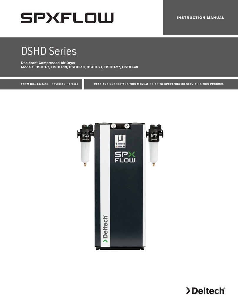
Deltech HG 5-10 User manual

HG SERIES
REFRIGERATED
COMPRESSED
AIR DRYERS
SERVICE DEPARTMENT: (724) 746-1100
Contents
GENERAL SAFETY INFORMATION ................................. 2
RECEIVING, MOVING, AND UNPACKING ....................... 2
INSTALLATION............................................................... 3
INSTRUMENTATION ...................................................... 4
CONDENSATE DRAIN VALVES ....................................... 4
START-UP/OPERATION.................................................. 4
SHUTDOWN.................................................................. 4
MAINTENANCE............................................................. 5
FIELD SERVICE GUIDE................................................... 6
ENGINEERING DATA ..................................................... 7
ELECTRICAL SCHEMATIC............................................... 7
AIR AND REFRIGERANT FLOW SCHEMATIC................... 7
WARRANTY .................................................................. 8
3252442 Rev. B 2/09
INSTRUCTION MANUAL
Models: HG 5-10, HG 15

2
GENERAL SAFETY INFORMATION
1. PRESSURIZED DEVICES:
This equipment is a pressure
containing device.
• Donotexceedmaximumoperating
pressure as shown on equipment
serial number tag.
• Makesureequipmentisdepressurizedbefore
workingonordisassemblingitforservice.
2. ELECTRICAL:
This equipment requires electricity to
operate.
• Installequipmentincompliancewith
all applicable electrical codes.
• Standardequipmentissuppliedwithelectrical
enclosuresnotintendedforinstallationinhazardous
environments.
• Disconnectpowersupplytoequipmentwhen
performinganyelectricalservicework.
3. BREATHING AIR:
• Airtreatedbythisequipmentmay
notbesuitableforbreathingwithout
furtherpurication.
Refertoapplicablestandardsand
specicationsfortherequirements
forbreathingqualityair.
RECEIVING, MOVING, AND UNPACKING
A. RECEIVING
Thisshipmenthasbeenthoroughlychecked,packed
andinspectedbeforeleavingourplant.Itwas
received in good condition by the carrier and was so
acknowledged.
CheckforVisibleLossorDamage.Ifthisshipment
showsevidenceoflossordamageattimeofdelivery
toyou,insistthatanotationofthislossordamagebe
made on the delivery receipt by the carrier’s agent.
B. UNPACKING
CheckforConcealedLossorDamage.Whena
shipment has been delivered to you in apparent
goodorder,butconcealeddamageisfoundupon
unpacking,notifythecarrierimmediatelyandinsist
on his agent inspecting the shipment. Concealed
damage claims are not our responsibility as our terms
areF.O.B.pointofshipment.
C. MOVING
In moving or transporting dryer, do not tip dryer onto
its side.
D. STORAGE
IMPORTANT: Do not store dryer in temperatures
above 130°F (54.4°C).

3
Compressor
Oil Removal
Filter
Aftercooler Automatic Drain
Dryer
Separator Receiver
TYPICAL COMPRESSED AIR SYSTEM
Locking Clip Stud
Existing Installation
New Installation
Dryer Hanger
OPTIONAL WALL MOUNTING BRACKET
(Retrofits models 8005 - 8015)
INSTALLATION
Ambient Air Temperature
Locate the dryer indoors where the ambient air
temperature will be between 40°F and 100°F. Intermittent
operation at ambient temperatures up to 113°F will not
damage the dryer but may result in a higher dew point
ordryershutdownduetohighrefrigerantdischarge
pressure (see Field Service Guide).
Do not operate air-cooled dryers at ambient air
temperatures below 40°F. Such operation may result in
lowsuctionpressure,causingfreeze-up.
Callyourlocaldistributorifprolongedoperationat
ambient temperatures above 100°F or below 40°F is
unavoidable.
Location and Clearance
Mount the dryer on a level base. Install the dryer in
aclean,well-ventilatedareatoreducefoulingofthe
condenser coils with dirt and dust.
Wall Mounting - Dryer may be wall mounted by using
anoptionalwallmountingbracket.clearancemustbe
maintained on all other sides as indicated.
Vapors and contaminants corrosive to copper and
aluminummustnotbeintheareaofthedryerorair
compressorintake.Allowatleast6inchesclearancefrom
thefrontandfromthecondensercoilserviceaccess.
Installthedryerwiththeframelevel.Anchorboltsarenot
required.
System Arrangement
Liquidwaterintheinletairwilladverselyaffectthe
performanceofthedryer.Installthedryerdownstreamof
anaftercoolerorseparatorsothatthetemperatureofthe
dryerinletairdoesnotexceed122°Fandtheinletairdoes
not contain any liquid water.
Mostcompressedairsystemsrequireltersforremoval
ofsolidandliquidcontaminants.Whenanoil-removal
lterisused,itshouldbeinstalleddownstreamofthe
refrigerateddryer.Thedryerwillremovesomeentrained
dirt,extendingthelifeofthereplaceablelterelement.
Outlet air temperature may be 10 to 30 degrees higher
than inlet air temperature. This is normal. Consult your
distributorifaloweroutletairtemperatureisrequired.
Piping and Connections
Pipingmustbefurnishedbytheuserunlessotherwise
specied.Connectionsandttingsmustberatedforthe
maximumoperatingpressuregivenonthedryerdata
plate and must be in accordance with applicable codes.
Supportallpiping;donotallowtheweightofanypiping
tostressthedryerorlters.Inletandoutletshutoffvalves
and a bypass valve are recommended. Piping should be
atleastthesizeoftheinletandoutletconnectionsto
minimizepressuredropintheairsystem.SeeEngineering
Datasectionfordryerinletandoutletconnections.
Removing Condensate
A separator with an automatic drain valve is supplied with
each dryer. The user must install a separate discharge line
atthedrainconnectiontocarryoffcondensatetoan
environmentally approved condensate collection/disposal
system. Securely anchor drain line to prevent whipping.
Ifcloggingoftheautomaticdrainisaproblem,installa
particulatelterbeforethedryertokeepsolidparticles
fromenteringthedryer.Contactyourlocaldistributorfor
theappropriateparticulatelter.
Electrical Connections (See Figure 1)
Dryer is designed to operate on the voltage, phase and
frequencylistedontheserialnumbertag.Referencetag
priortomakingelectricalconnection.Dryersaresupplied
withacordandplug.Installinreceptacleofproper
voltage.
Operationofdryerswithimproperline
voltageconstitutesabuseandcouldaffectthedryer
warranty.

4
INSTRUMENTATION
ON/OFF Switch
ThedryerisequippedwithanON/OFFswitchonthefront
panel. A light signals when the dryer is on.
CONDENSATE DRAIN VALVES
A float operated drain is housed in a metal bowl. It will
automatically drain the condensate.
START-UP/OPERATION
Follow the procedure below to start your dryer. Failure
tofollowtheprescribedstart-upprocedurewillinvalidate
thewarranty.Ifproblemsariseduringstart-up,callyour
distributor.
RefertoSerialNumberTagfordryer
operatingcapacity.Donotexceedrecommendedcapacity.
Drainconnectionsmustbemadebeforethedryercanbe
operated.Thedryersarefullyautomaticandrequireno
auxiliarycontrols.
1. Connectinletandoutletlinestothedryer.Reference
dryerindentationsandinstructiontagforappropriate
inlet and outlet connections.
2. Route drain connections to a condensate separator or
approved collection point.
3. Turntheon/offswitchtoon.Doublecheck
connections.
4. Afterthedryerhasbeenrunningfor30minutes:
a. Checkthaton/offlightedswitchisglowing.If
lightisnotglowing,unplugunitandrefertoField
ServiceGuideforadditionalinformationorcall
your local distributor.
b. Conrmthatcondensateisdischargingfromthe
drain. This can only be done when there is air flow
through the dryer.
ReferenceSerialNumberTagfor
appropriatepowerrequirement/connectionrating.Make
other dryer connections prior to connecting power
source.
The dryer is designed to run continuously. Let the
dryerrunevenwhenthedemandforcompressedairis
interrupted;thedryerwillnotfreezeup.
Operating Check Points
1. Power light is on, light is illuminated.
2. Condensate is discharging properly.
SHUTDOWN
Whenthedryermustbeshutdownformaintenanceor
otherreasons,usethefollowingprocedure:
1. Turnthepoweron/offswitchtooff.
2. Disconnect the main power supply.
Ifmechanicalrepairsaretobemadeorserviceis
performed,venttheinternalpressureofthedryerto
atmospheric pressure. Restart the dryer according to the
start-up instructions.
Disconnectpowersupplyanddepressurize
dryerbeforeservicing.Dismantlingorworkingonany
componentofthecompressedairsystemunderpressure
maycauseequipmentfailureandseriouspersonalinjury.

5
MAINTENANCE
Thedryersrequirelittlemaintenanceforsatisfactory
operation.Gooddryerperformancecanbeexpectedif
thefollowingroutinemaintenancestepsaretaken.
Daily Maintenance
Checktheseparatorforcondensatedischarge.Ifno
dischargeisevident,depressurizeanddismantle.Clean
separator housing with mild soap and water. Discard
automatic float drain and replace.
Monthly Maintenance
Inspect the condenser coils. Remove accumulated dust
anddirtwithasoftbrushorwithairfromanOSHA
approvedcompressedairnozzlethatlimitsthedischarge
pressure to 30 psig.
General
Forcontinuedgoodperformanceofyourrefrigerated
dryer,allrefrigerationsystemmaintenanceshouldbe
performedbyacompetentrefrigerationmechanic.
NOTE:Beforecorrectivemaintenanceisdoneduringthe
warranty period, call your local distributor and proceed
accordingtoinstructions.Refertothewarrantyforlimits
ofyourcoverage.
Parts List
Item All Models
On/OffSwitch 3245021
Float Drain Kit 3090900
Returns to Manufacturer
Ifthedryeroracomponentofthedryermustbe
returnedtothemanufacturer,rstcallyourlocal
distributorforareturnauthorizationnumberand
shippingaddress.Yourdistributorwillinformyouwhether
thedryeroronlyacomponentmustbereturned.Mark
thepackagewiththereturnauthorizationnumberand
shipfreightprepaidasdirectedbyyourlocaldistributor.

6
FIELD SERVICE GUIDE
Problemsmostfrequentlyencounteredwithrefrigerated
dryersarewaterdownstreamofthedryerandexcessive
pressuredrop.Mostcausescanbeidentiedand
remediedbyfollowingthisguide.
Closedrefrigerationsystemsarepotentiallydangerous.
Workontherefrigerationsystemmustbedoneonly
byacompetentrefrigerationmechanic.Donotrelease
uorocarbonrefrigerantstotheatmosphere.All
refrigerantsmustberecoveredperEPArequirements.Do
notsmokewhenarefrigerationleakissuspected.Burning
materialsmaydecomposerefrigerants,formingatoxic
gasoracidsthatmaycauseseriousinjuryandproperty
damage.Beforedismantlinganypartofthedryeror
compressed air system, completely vent the internal
pressure to the atmosphere.
PROBLEM POSSIBLE CAUSE REMEDY
WATER DOWNSTREAM OF DRYER
SYMPTOM:
Nodischargefromseparatordrain
trap.
Failureofdraintrap. Replace float mechanism.
SYMPTOM:
Dryer inlet air temperature too
high.
Aftercoolermalfunction. Checkaftercoolerdischargetemperature
and reduce to dryer design condition
(122°Fmax).
SYMPTOM:
Refrigerantcompressorstopped. Leakinrefrigerantsystem. Consult local distributor.
Compressor overheated. Turndryeroff,wait30minutes;turn
dryeron.(Motorthermostatself-
starting)
Compressor burned out. Consult local distributor.
Inlet air temperature too high. Reduceaftercoolerdischarge
temperature to design conditions.
Excessiveairow. Checkairow&systemcapacity.
Reduceairoworre-sizeandreplace
system.
Condenserfouledorclogged. Clean condenser.
High ambient temperature. Ventilate area.
ImproperadjustmentofExpansion
Valve.
Consult Factory.
HIGH PRESSURE DROP
SYMPTOM:
Low outlet pressure. Dryerundersized(maycausewater
downstreamofdryer).
Checkairowanddryercapacity.
Reduceairoworre-sizeandreplace
dryer.
Blockedseparator. Dismantle&cleanorreplaceseparator.
Dryerfreezingup. Consult local distributor.

7
ELECTRICAL SCHEMATIC AIR AND REFRIGERANT FLOW SCHEMATIC
Figure 1 Figure 2
HEAT EXCHANGER
REHEATER
AUX. CONDENSER
AIR OUTLET
SEPARATOR
EVAPORATOR
CHILLER
DRAIN OUTLET
AIR INLET
LIQUID RECEIVER
/ FILTER DRYER
CONSTANT PRESSURE
EXPANSION VALVE
REF. COMPRESSOR
ON/OFF SWITCH
WITH RUNNING LAMP
R
25
6
PTC STARTER
SM
COMP.
1PH
C
OVERLOAD
PROTECTOR
ENGINEERING DATA
SCFM 10 15
SPECIFICATIONS
Rated Capacitya-(scfm) 10 15
Inlet /Outlet Connections - (inches) 3/8 3/8
Dimensions
Height - (inches) 15.4 15.4
Length - (inches) 12.6 12.6
Width - (inches) 12.6 12.6
PowerSupply-(V/Ph/Hz) 115/1/60 115/1/60
RefrigerantCompressorRating-(hp) 1/8 1/7
InputPower-(kW) 0.21 0.24
RefrigerantTypebR-134a R-134a
MINIMUM - MAXIMUM OPERATING CONDITIONS
Min.-Max.InletAirPressure(compressedairatinlettodryer) 30 - 250 psig 30 - 250 psig
Min.-Max.InletAirTemperature(compressedairatinlettodryer) 40°F - 122°F 40°F - 122°F
Min.-Max.AmbientTemperature 40°F - 113°F 40°F - 113°F
aRatingconditionsare100°Finlettemperature,100psiginletpressure,100%inletrelativehumidity,100°Fambienttemperature@60Hz.PerCAGIADF-100
bRefertodryerdataplateforrefrigerantcharge.

WARRANTY
Themanufacturerwarrantstheproductmanufacturedbyit,whenproperlyinstalled,operated,applied,andmaintainedinaccordancewithproceduresand
recommendationsoutlinedinmanufacturer’sinstructionmanuals,tobefreefromdefectsinmaterialandworkmanshipforaperiodofone(1)yearfrom
thedateofshipmenttothebuyerbythemanufacturerormanufacturer’sauthorizeddistributor,oreighteenmonthsfromthedateofshipmentfromthe
factory,whicheveroccursrst,providedsuchdefectisdiscoveredandbroughttothemanufacturer’sattentionwithintheaforesaidwarrantyperiod.
Themanufacturerwillrepairorreplaceanyproductorpartdeterminedtobedefectivebythemanufacturerwithinthewarrantyperiod,providedsuch
defectoccurredinnormalserviceandnotasaresultofmisuse,abuse,neglectoraccident.Normalmaintenanceitemsrequiringroutinereplacementare
notwarranted.Thewarrantycoverspartsandlaborforthewarrantyperiod.Repairorreplacementshallbemadeatthefactoryortheinstallationsite,
atthesoleoptionofthemanufacturer.Anyserviceperformedontheproductbyanyoneotherthanthemanufacturermustrstbeauthorizedbythe
manufacturer.
Unauthorizedservicevoidsthewarrantyandanyresultingchargeorsubsequentclaimwillnotbepaid.
Productsrepairedorreplacedunderwarrantyshallbewarrantedfortheunexpiredportionofthewarrantyapplyingtotheoriginalproduct.
Theforegoingistheexclusiveremedyofanybuyerofthemanufacturer’sproduct.Themaximumdamagesliabilityofthemanufactureristheoriginal
purchasepriceoftheproductorpart.
THE FOREGOING WARRANTY IS EXCLUSIVE AND IN LIEU OF ALL OTHER WARRANTIES, WHETHER WRITTEN, ORAL, OR STATUTORY, AND IS EXPRESSED IN LIEU OF
THE IMPLIED WARRANTY OF MERCHANTABILITY AND THE IMPLIED WARRANTY OF FITNESS FOR A PARTICULAR PURPOSE. THE MANUFACTURER SHALL
NOT BE LIABLE FOR LOSS OR DAMAGE BY REASON OF STRICT LIABILITY IN TORT OR ITS NEGLIGENCE IN WHATEVER MANNER INCLUDING DESIGN, MANUFACTURE
OR INSPECTION OF THE EQUIPMENT OR ITS FAILURE TO DISCOVER, REPORT, REPAIR, OR MODIFY LATENT DEFECTS INHERENT THEREIN.
THE MANUFACTURER, HIS REPRESENTATIVE OR DISTRIBUTOR SHALL NOT BE LIABLE FOR LOSS OF USE OF THE PRODUCT OR OTHER INCIDENTAL OR
CONSEQUENTIAL COSTS, EXPENSES, OR DAMAGES INCURRED BY THE BUYER, WHETHER ARISING FROM BREACH OF WARRANTY, NEGLIGENCE OR STRICT LIABILITY
IN TORT.
Themanufacturerdoesnotwarrantanyproduct,part,material,component,oraccessorymanufacturedbyothersandsoldorsuppliedinconnectionwith
thesaleofmanufacturer’sproducts.
AUTHORIZATION FROM THE SERVICE DEPARTMENT IS NECESSARY BEFORE MATERIAL IS
RETURNED TO THE FACTORY OR IN-WARRANTY REPAIRS ARE MADE.
SERVICE DEPARTMENT: (724) 746-1100
© 2009 SPX Corporation. All rights reserved.
Improvements and research are continuous at Deltech. Specifications may change without notice.
DELTECH, AN SPX BRAND
1000 PHILADELPHIA STREET
CANONSBURG, PA 15317-1700 U.S.A.
TEL | 724 | 745 | 8647 FAX | 724 | 745 | 4967
Email: [email protected]
www.deltech-spx.com
This manual suits for next models
1
Table of contents
Other Deltech Dehumidifier manuals
