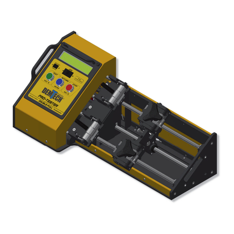
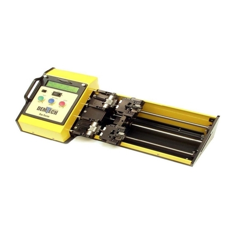
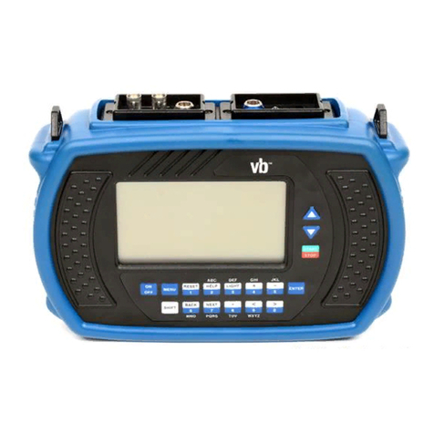
Demtech Pro-Tester SE User manual

Pro-Tester SE
Pro-Tester SE Operator’s Manual
Model Number: T-0100SE/A
Revision: B

Rev. B, October 2020
Page ii Pro-Tester SE Operator’s Manual
© Copyright 2020 by DEMTECH Services, Inc.
All Rights Reserved
Scope of Manual:
This manual contains procedures for safety, general unpacking,
set-up, and operation of your DEMTECH Services, Inc. Pro-Tester Hi-Pull
TM
Field
Tensiometer.
The text of this publication, or any part thereof, may not be reproduced or transmitted in any
form or by any means, electronic or mechanical, including photocopying, recording, storage in
an information retrieval system, or otherwise, without prior written permission of DEMTECH
Services, Inc.
Notice
Patents have been granted and/or patent applications are pending or are in the process of
preparation on all DEMTECH Services, Inc. developments.
The material in the manual is for informational purposes only and is subject to change without
notice.
DEMTECH Services, Inc. assumes no responsibility for any errors that may appear in this
manual.
Printed in the USA
Manual Number: T-OPERATOR’S MANUAL/PRO-TESTER SE, Revision: B
DEMTECH Services, Inc.
6414 Capitol Avenue Diamond Springs, CA 95619 U.S.A.
Telephone: (530) 621-3200
Toll Free: (888) 324-9353
Fax: (530) 621-0150
Web Site: www.demtech.com

Rev. B, October 2020
Pro-Tester SE Operator’s Manual Page iii
Table of Contents
1
SAFETY PRECAUTIONS…………………………………………………..PAGE 1
2
GENERAL SAFETY & MAINTENANCE INFORMATION…………….PAGE 2
2.1
Intended Use…………………………………………………………………...Page 2
2.2
Maintenance…………………………………………………………………...Page 2
3
GENERAL PRODUCT DATA……………………………………………...PAGE 3
4
SITE PREPARATION……………………………………………………….PAGE 4
5
UNPACKING & INSTALLATION INSTRUCTIONS……………………PAGE 4
5.1
Unpacking and Preparation…………………………………………………...Page 5
5.2
Electrical Plug Connection……………………………………………………..Page 5
5.3
Control Panel…………………………………………………………………..Page 7
5.4
Loading Samples………………………………………………………………Page 9
5.5
Settings……………………………………………………………………….Page 10
5.6
Elongation Definition………………………………………………………...Page 10
6
FACTORY SERVICING…………………………………………………...PAGE 13
7
USER INTERFACE MENU TREE………………………………………..PAGE 13
8
SYSTEM WIRING DIAGRAM……………………………………………PAGE 14
9
PRO-TESTER HI-PULL
TM
WARRANTY…………………………………PAGE 14

Rev. B, October 2020
Page 1 Pro-Tester SE Operator’s Manual
1Safety Precautions
Safety precautions for operating personnel and equipment:
WARNING 1: Operating personnel should perform only the procedures described and
recommended in this manual. Only qualified service personnel familiar with electrical
shock hazards and mechanical entanglement hazards present inside the equipment should
perform disassembly or corrective maintenance of the equipment.
WARNING 2: To avoid shock hazards, the equipment must be grounded with an adequate
earth ground in accordance with local and national electrical codes.
WARNING 3: The locations of potentially dangerous voltages and other hazards are
identified and labeled on the equipment. Be careful to observe these warnings when installing,
operating, maintaining or servicing the equipment. Observe all warnings in this manual.
WARNING 4: Make sure to turn off the equipment power and remove the ~ (AC) line cord
from the power outlet before attempting to service the equipment. Do not perform service
unless you are qualified and trained to do so.
WARNING 5: This product is intended for operator attended operation only. This product
should never be left unattended at any time while it is plugged in and the power is turned on.
Incorrect use of the product such as overheating of the material can present a fire and explosion
hazard, especially near combustible materials and explosive gases.
WARNING 6: This product is intended for operation in dry environments only. Higher
humidity environments should be kept non-condensing by avoiding large temperature swings.
WARNING 7: Do not touch the main housing, air nozzle and/or output molten material when
they are hot as they can cause burns. After use allow sufficient time for the product to cool to
room temperature before handling and stowing. Do not point or direct the hot air flow and the
output molten material in the direction of personnel.
CAUTION 1: Observe the precautions given on the equipment and within this manual to
prevent damage to the equipment.
CAUTION 2: Before connecting the equipment to its electrical power source, check that the
~ (AC) voltage, frequency and current to be supplied to the equipment are correct and
match the serial plate affixed to the system.
CAUTION 3: Use proper handling and packaging procedures for Electro-Static Discharge
(ESD) sensitive Printed Circuit Boards (PCB’s). Assume that all PCB’s are sensitive to
potential damage from ESD.
CAUTION 4: Unauthorized personnel should not remove from the equipment those panels or
covers that are provided for protection and/or require a tool to remove.

Rev. B, October 2020
Pro-Tester SE Operator’s Manual Page 2
2General Safety & Maintenance Information
The DEMTECH Services, Inc. Pro-Tester SE
TM
field tensiometer, hereinafter referred to as
the Pro-Tester SE
TM
, Pro-Tester
TM
, or tensiometer is a high voltage piece of equipment.
Always disconnect the power source before performing any service and/or maintenance
procedures on the tensiometer. Never lift, pull or carry the welder by the power cord or
electrical connection. Always maintain slack in any extension cords connected to the
tensiometer while in operation to avoid damage to the power connections. At all times
while operating the tensiometer keep hands, fingers and other body parts well clear of the
rotating screw and grip assemblies.
2.1
Intended Use
The Pro-Tester SE
TM
is intended as professional use equipment and is not intended for sale
to the general public.
The Pro-Tester SE
TM
has been manufactured utilizing the latest technology and current
safety standards and regulations. However, improper use or abuse may lead to hazardous
conditions for the user or other personnel or cause damage to the tensiometer.
Always keep this manual with the Pro-Tester
TM
at or near the location where the tensiometer
is being used so that it can be referred to quickly and easily.
The technician assigned to operate this tensiometer must have read through and become
familiar with this manual, particularly all safety information, before operating the Pro-
Tester
TM
.
No changes and/or modifications shall be made to the Pro-Tester
TM
especially as it relates
to safety.
2.2
Maintenance
Maintenance, inspection and adjustment of the Pro-Tester
TM
shall only be carried out by
qualified personnel. Before removing or installing spare parts or performing other repair
operations to the tensiometer, consult DEMTECH Services, Inc. or your authorized
DEMTECH service center for advice on proper procedures. This will help insure a safe
and successful outcome. Always make sure all screw connections are tight before
attempting to operate the welder after maintenance and/or repair procedures. Also make
sure all covers, guards, and other safety devices have been fully reinstalled before use.

Rev. B, October 2020
Page3 Pro-TesterSEOperator’sManual
3General Product Data
The DEMTECH Services, Inc. Pro-Tester SE
TM
Field Tensiometer, hereinafter referred to
as the Pro-Tester
TM
, dramatically speeds the field testing of welded seam samples by
providing an easy to load grip. This arrangement combined with state-of-the-art electrical
and electronics controls and an easy to use User Interface (UI) makes the task of performing
field sample tests much more efficient. The highly integrated and automated operation of
the Pro-Tester
TM
eliminates cumbersome setup and speeds up process time while providing
a very rugged and reliable system. The one button operation combined with automatic
return saves time. The enclosed controller system is easy to maintain. You can be assured
the Pro-Tester
TM
has been built using the highest quality materials available which include
Billet Aluminum and ground and hardened steel. DEMTECH Services, Inc. strives to make
our systems easy to use and built to last. Just like all other DEMTECH Services, Inc.
products, even a first-time user will be productive in minutes. With easy adjustments and
a one touch operation, you will be getting test results within minutes of installation.
To operate and navigate the various features of the Pro-Tester
TM
simply follow the text
prompts at the bottom of the Liquid Crystal Display (LCD) screen. Significant
development was spent making the system very easy to operate by even a novice operator
by simply following the screen prompts.

Rev. B, October 2020
Pro-Tester SE Operator’s Manual Page 4
4Site Preparation
Before proceeding with the unpacking and installation instructions in the following
section(s) make sure the work site is prepared and ready to use the Pro-Tester
TM
. You should
have an adequate power source capable of providing clean Alternating Current (AC)
power at 110 or 220 Volts at the rated current. Refer to the system serial plate affixed to
the rear of the system for the voltage and current requirements of your system. The install
area should be clean, dry and free of debris and provide adequate working area to allow
efficient and effective use of the system.
Carefully follow the detailed unpacking and installation instructions provided in this
manual.
5Unpacking & Installation Instructions
This section contains instructions for the unpacking, placement and installation of the Pro-
Tester
TM
. Carefully review the following information, sub-sections and each procedure
before beginning unpacking and installation of the system.
The Pro-Tester
TM
comes complete in a reusable portable shipping/transport container. The
system can be operated from within the container our removed and placed onto a work bench
or appropriate platform for use. When not in use the Pro-Tester
TM
should always be stored in
the shipping/transport container to protect it from the elements and potential damage.
Note: The system illustrated in this manual shows ALL available features for the Pro-
Tester
TM
, therefore, your system may vary slightly in appearance from that depicted.

Rev. B, October 2020
Page5 Pro-TesterSEOperator’sManual
5.1
Unpacking and Preparation
a. Before opening the shipping/transport container and unpacking the system, inspect the
outside of the container thoroughly for any signs of mishandling or damage during
shipping. Report any damage to the shipping carrier immediately and do not proceed
with unpacking. Since the shipment is made FOB factory, you should consult your
administration concerning claims for shipping damage. Please notify DEMTECH
Services, Inc. immediately in writing of any shipping damage.
b. Unlatch and open the shipping/transport container lid and inspect inside the container
and equipment thoroughly for any signs of mishandling or damage during shipping.
Report any damage to the shipping carrier immediately and do not proceed with
unpacking. Since the shipment is made FOB factory, you should consult your
administration concerning claims for shipping damage. Please notify DEMTECH
Services, Inc. immediately in writing of any shipping damage.
c. Make note of the orientation of the equipment and packing foam inserts inside the
shipping container to facilitate any repackaging requirements in the future.
d. To avoid injury and/or damage to the system, be sure to use adequate care when lifting,
removing or replacing the system into the shipping/transport container.
e. You may operate the system from within the shipping/transport container or remove it
and place it in an appropriate location suitable for the testing you intend to perform.
5.2
Electrical Plug Connection
a. Verify proper operation of the Pro-Tester
TM
before proceeding with the remainder of the
installation. The Pro-Tester
TM
is equipped with a “soft-start” feature. This feature
utilizes a toggle power switch on the rear of the system. Toggle the switch up to turn
the system ON. Toggle the switch down to turn the system OFF. This feature provides
a built in safety to protect the system during connection to a field generator by
automatically turning the power off to the system any time AC power is disconnected
either by turning off the generator or unplugging the power cord. Upon startup
generators can produce significant power surges which can be harmful to the Pro-
Tester
TM
. This soft-start feature eliminates ill effects from this phenomenon. Find the
Power Cord included with your system and plug one end into the appropriate connecter
at the rear of the system (refer to Figure 1). Plug the other end into an electrical outlet
supplying the proper ~(AC) power. Toggle the Power Switch to the ON position (refer
to Figure 5.1).

Rev. B, October 2020
Pro-Tester SE Operator’s Manual Page 6
b. The system LCD should light up, go through a self-diagnostic test and then prompt the
user to press ENTER to initiate the initialization/calibration sequence. Press ENTER
to perform the initialization/calibration procedure. For the proper operation of the Pro-
Tester
TM
do not HALT or skip the procedure.
c. The system will first move the grip head in (left) to find the home position, then out
(right) to calibrate travel speed. After a short pause the grip will then move back in
(left) and stop at the A or B grip separation position depending on which is selected on
the Control Panel. This procedure verifies the Pro-Tester
TM
is in good working
condition. If the system performs as described, you are now ready to operate the system.
If the system does not perform any of the functions described above please contact
DEMTECH Services, Inc.
Figure 5.1
M002
Power Cord
With IEC 60320
Connector
(P/N T-111)
Fuse
Holde
r
Power
ON/OFF
Switch

Rev. B, October 2020
Page7 Pro-TesterSEOperator’sManual
5.3
Control Panel
The User Interface Control Panel is the main operator interface device for operating the
Pro-Tester
TM
. Each component of the Control Panel is identified below (refer to Figure 5.3).
Figure 5.3
A
B
C
D
E
F

Rev. B, October 2020
Pro-Tester SE Operator’s Manual Page 8
a. Liquid Crystal Display (LCD): The LCD is a 40 Character by 4 Line display device
which provides main system operation information for the Control Panel. It provides
all key operating information and allows the user to input various system settings.
b. JOG
/
: This switch allows the user to jog (move) the movable sample grip at an
accelerated rate in and out during setup and operation of the system and is used to
change various settings during Menu Mode operation (refer to Section 6.5).
c. Grip Start Position Toggle Switch A/B: This switch allows the user to select between
one of two grip separation settings. This allows quick transition from one separation
length to another. Grip separations A and B can be set through the Menu Mode (refer
to Section 6.5).
d. Test/Yes/: This button is used to initiate a Test or in Menu Mode to navigate the
screen tree.
e. Return Enter: This button is used to return the grips after a test or in Menu Mode to
navigate the screen tree.
f. Stop/No/⇩: This button is used to stop a Test or in Menu Mode to navigate the screen
tree.

Rev. B, October 2020
Page9 Pro-TesterSEOperator’sManual
5.4
Loading Samples
Loading samples is very simple with the Pro-Tester
TM
. To load a sample open both jaws of
the sample grip assemblies. The left grip is a cam clamp and is opened by toggling the
cam handle to the right (open). The right grip is a screw clamp and is opened by unscrewing
the tri-handle counter-clockwise (open).The sample is prepared by bending the ends to be
clamped so they can be easily loaded into the grips. Load the sample from the top of the
grip until the sample rests against the stop tabs then apply the left and right grip clamps
(refer to Figure 5.4). If loading a 4” (100 mm) test coupon, align the edges of the sample
with the edges of the grip frame in order to center the coupon. The stop tabs will need to
be removed in order to load a 4” (100 mm) coupon.
Figure 5.4
Stop
Tab
T-035 A M004

Rev. B, October 2020
Pro-Tester SE Operator’s Manual Page 10
5.5
Settings
a. The Pro-Tester
TM
requires various settings for proper operation. These settings are
easily accessed via the Menu Mode of operation. To enter the Menu Mode, make sure
the Pro-Tester
TM
is on and at the main operating screen (Refer to Page 15).
Simultaneously press and hold the YES and NO buttons on the Control Panel for
several seconds. This procedure puts the system into Menu Mode. This mode of
operation allows the user the set various system parameters. For a complete listing of
all of the features refer to the diagram on page 15.
b. All of the settings required to operate the Pro-Tester
TM
come factory set for most users
and should not need setting. However, if your particular installation requires setting
any parameters enter the Menu Mode and follow the screen prompts to navigate the
screen menu.
c. Figure 7.1 on page 15 is a Menu Tree drawing. This drawing can be very helpful if
you are trying to find a particular function or setting you wish to access. Use the
drawing to locate the particular item you want to access. Once located, follow the
tree back to the top level. Next, utilizing the user interface on the Pro-Tester
TM
,
proceed back down through the menu structure using the drawing as a guide to access
the particular screen you want.
5.6
Elongation Definition
If you intend to use the strain (elongation) feature of the Pro-Tester
TM
tensiometer it is
important to understand both the definition of this feature/function and how it is intended
to be used. Proper understanding requires the definition of some basic terms. These
terms are defined below.
a. Grip Separation (GS): The distance between the grip point on each of the left and
right sample grip assemblies (refer to Figure 5.5). There are two user settable
distances, A or B, which have been factory set for 1.7 and 3.5 inches respectively.
The operator must be aware of these values and change the settings if necessary (refer
to Section 5.5) to accommodate the particular sample to be tested.
b. Weld Extrusion (Squeeze-out): The area of a weld whereupon becoming molten the
parent material extrudes (is squeezed) out from between the pressure zone of the
welding tool and then cools. This extruded material does not usually provide an
acceptable bond of the parent material and should not be considered part of the weld
(refer to Figure 6C).

Rev. B, October 2020
Page11 Pro-TesterSEOperator’sManual
c. Weld Width (WW): The center-to-center distance between the two welds of a dual-
track weld (refer to Figure 6A) or the edge-to-edge distance on a solid weld (refer to
Figure 6B). It is important when measuring/calculating these distances that the
operator only include the actual width of the weld. The width of the weld is defined
as only that area where the two sheets of parent material have been appropriately
bonded by both heat and pressure. During this process some parent material may
extrude beyond the pressure zone of the welding tool (refer to Weld Extrusion
definition). This extruded material does not usually provide an acceptable bond of
the parent material and should therefore be excluded from any measurements made
for this test.
d. Gauge Length (GL): This is the base value used by the Pro-Tester
TM
for determining
elongation percentage. It is the Grip Separation once the initial tension value has been
reached minus the Weld Width (GS – WW = GL). For example if your Grip
Separation was 4 inches and your Weld Width was 1 1/2 inches then your Gauge
Length would be 2 1/2 inches (4 - 1.5 = 2.5). It is this value that is used to determine
elongation. Elongation is calculated as the percentage of change (increase) of the
Grip Separation related to Gauge Length. For example if your Gauge Length is 2 1/2
inches and the grips had separated 1 1/4 inches at the completion of your test then the
elongation would be 50% (1.25 / 2.5 = .50). If your Gauge Length is 2 1/2 inches and
the grips had separated 2 1/2 inches at the completion of your test then the elongation
would be 100% (2.5 / 2.5 = 1.00).
It is on this basis that the Pro-Tester
TM
has been designed and programmed to operate when
performing elongation testing.
Figure 5.5
T-035 A M004

Rev. B, October 2020
Pro-Tester SE Operator’s Manual Page 12
Figure 6A
Figure 6B
Figure 6C
Figure 6

Rev. B, October 2020
Page13 Pro-TesterSEOperator’sManual
6Factory Servicing
In the event your Pro-Tester SE
TM
should require factory service, the entire welder needs to
be returned to the factory. Refer to the following step for preparing the Pro-Tester SE
TM
for
return.
Carefully pack the Pro-Tester SE
TM
in the reusable portable shipping/storage case provided
with the welder for return to DEMTECH Services, Inc.’s factory for service. Unless
previous arrangements are made, shipping charges and insurance are the responsibility of
the customer. Ship the packaged Pro-Tester SE
TM
to DEMTECH Services, Inc. at:
DemTech Services, Inc
Ship to address: 6414 Capitol Avenue
Diamond Springs, CA 95619
U.S.A.
7User Interface Menu Tree
Refer to Page 15 for the Pro-Tester SE
TM
Menu Tree drawing. This drawing can be very
helpful if you are trying to find a particular function or setting you wish to access. Use the
drawing to locate the particular item you want to access. Once located, follow the tree
back to the top level. Next, utilizing the user interface on the Pro-Tester
TM
, proceed back
down through the menu structure using the drawing as a guide to access the particular
screen you want. To enter the Menu Mode make sure the Pro-Tester
TM
is on and at the main
operating screen (Refer to Page 15). Simultaneously press and hold the YES and No
buttons on the Control Panel for several seconds.

Rev. B, October 2020
Pro-Tester SE Operator’s Manual Page 14
8System Wiring Diagram
Refer to Page 16 for the Pro-Tester
TM
System Wire Diagram. This drawing can be very
helpful in identifying and/or troubleshooting basic wiring or interconnection issues related
to the Pro-Tester
TM
.
9Pro-Tester SE
TM
Warranty
See page 17 for the DEMTECH Services, Inc. product warranty.

Rev. B, October 2020
Page15 Pro-TesterSEOperator’sManual
Figure 7.1
T-0100HP A M001

Rev. B, October 2020
Pro-Tester SE Operator’s Manual Page 16
Figure 8.1

Rev. B, October 2020
Page17 Pro-TesterSEOperator’sManual
Warranty
DEMTECH Services, Inc. warrants all equipment of its manufacture to be free from defects in
materials, workmanship, mechanical parts, and labor for a period of one year from the date of shipment
to the original buyer and ninety days for electrical. This warranty excludes normal wear items such as
gears, bearings and chains. The liability under this warranty is limited to replacement parts and labor
on equipment when the equipment is returned prepaid to the factory or its authorized service center with
prior authorization from DEMTECH Services, Inc., and upon examination by DEMTECH Services, Inc.,
is determined to be defective. At DEMTECH Services, Inc.'s option, a service representative may be
dispatched to the equipment location.
As an additional protection, DEMTECH Services, Inc. warrants that for a period of 90 days from the
date of shipment to the original buyer, pending prior authorization from DEMTECH Services, Inc., there
will be no charge for service related shipping of parts and/or equipment or for authorized travel of a
service representative to the equipment location. After 90 days, all costs incurred for shipping the
equipment or parts thereof or for travel are the responsibility of the buyer. Our warranty for this equipment
is rendered void if the unit has been repaired, taken apart or modified, or attempted to be, unless such
actions have been taken in accordance with written instructions received from DEMTECH Services,
Inc. The warranty is also void if the equipment has been subjected to abuse, accident or other abnormal
conditions.
IF ANY FAULT DEVELOPS,
THE FOLLOWING STEPS SHOULD BE TAKEN:
1.
Notify DEMTECH Services, Inc. by calling 1-888-324-9353. Overseas customers should contact
the local DEMTECH authorized service center. Please be prepared with the model number, serial
number and full details of the difficulty. Upon receipt of this information, service data or shipping
instructions will be provided by DEMTECH Services, Inc. Do not return the unit for repair without
first contacting the factory or its representative for instructions.
2.
After the initial 90 day period, on receipt of shipping instructions, forward the equipment prepaid
to the factory or its authorized service center as instructed. If requested, an estimate of the
charges will be made before work begins, especially with those cases where the DEMTECH Services,
Inc. product is not covered by the warranty.
3.
If the original carton and packing are not available, the product should be packed in a container
with a strong exterior and surrounded by a protective layer of shock-absorbing material.
DEMTECH Services, Inc. advises returning the equipment at full value to the carrier.
DEMTECH Services, Inc. reserves the right to make changes in design at any time without incurring
any obligation to install the same changes on units previously purchased.
This warranty states the essence of the obligations or liabilities on the part of DEMTECH Services, Inc.
THE FORMAL, COMPLETE AND EXCLUSIVE STATEMENT OF DEMTECH SERVICES, INC.’S
WARRANTY IS CONTAINED IN ITS QUOTATIONS, ACKNOWLEDGEMENTS AND INVOICES.
DEMTECH Services, Inc. neither assumes, nor authorizes any person to assume for it, any liability in
connection with the sale of its equipment other than those set forth herein.
This manual suits for next models
1
Table of contents
Other Demtech Measuring Instrument manuals
Popular Measuring Instrument manuals by other brands

PCB Piezotronics
PCB Piezotronics ICP 350C24 Installation and operating manual
KROHNE
KROHNE OPTIWAVE 6300 C Handbook
Lovato
Lovato DMG7000 instruction manual

PRECISION DIGITAL
PRECISION DIGITAL PD6800 instruction manual
Ampetronic
Ampetronic Loopworks R1 Quick-Start Guide & Handbook
Tenmars
Tenmars TM-197 user manual
