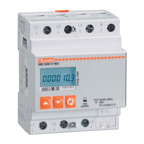
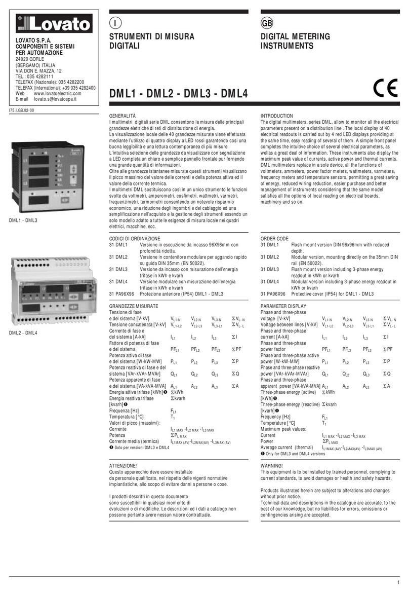
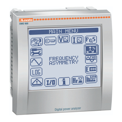
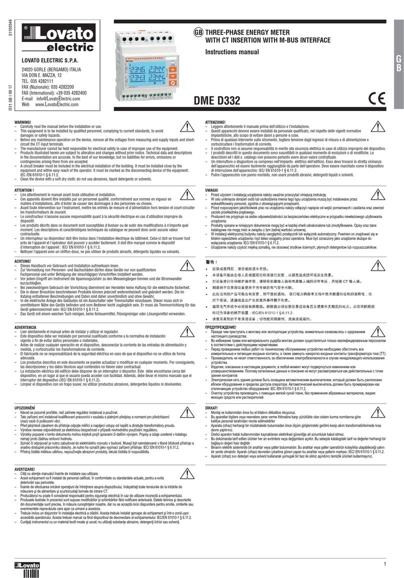
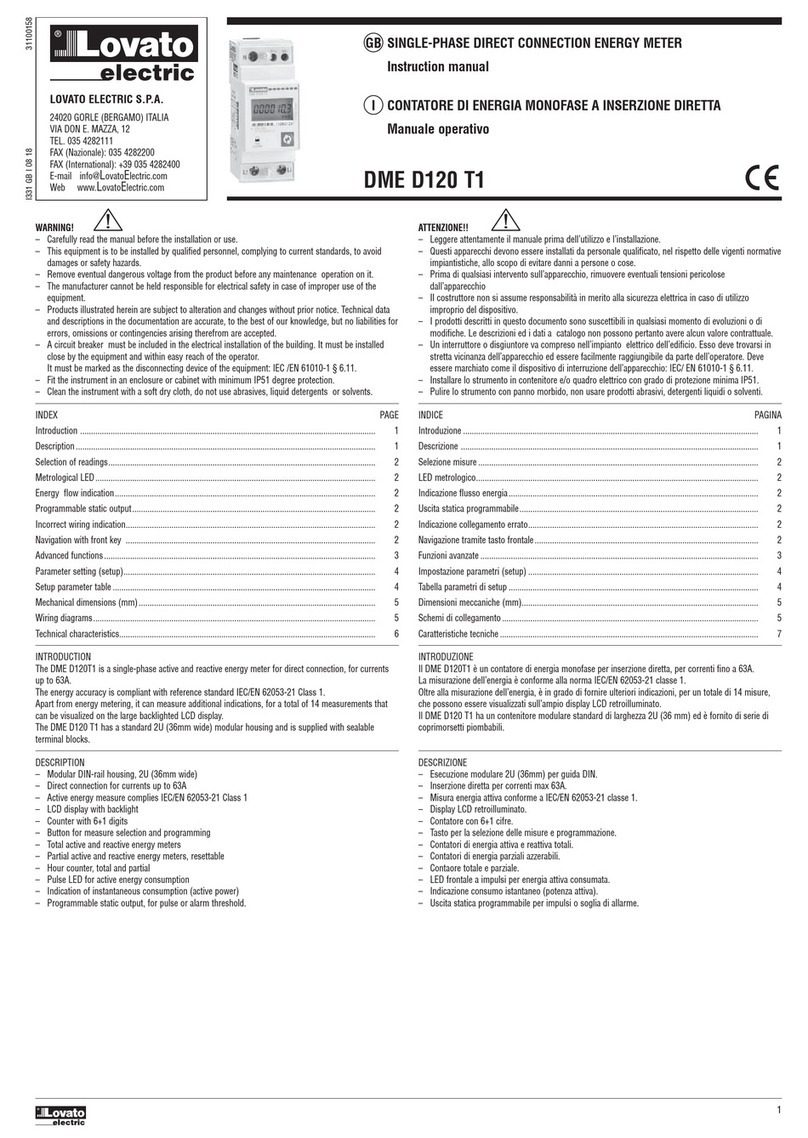
Lovato DMG7000 User manual

WARNING!
Carefully read the manual before the installation or use.
This equipment is to be installed by qualified personnel, complying to current standards, to
avoid damages or safety hazards.
Before any maintenance operation on the device, remove all the voltages from measuring and supply inputs and
short- circuit the CT input terminals.
The manufacturer cannot be held responsible for electrical safety in case of improper use of the equipment.
Products illustrated herein are subject to alteration and changes without prior notice. Technical data and
descriptions in the documentation are accurate, to the best of our knowledge, but no liabilities for errors, omissions
or contingencies arising there from are accepted.
A circuit breaker must be included in the electrical installation of the building. It must be installed close by the
equipment and within easy reach of the operator. It must be marked as the disconnecting device of the
equipment: IEC /EN 61010-1 § 6.11.3.1
Clean the device with a soft dry cloth; do not use abrasives, liquid detergents or solvents.
ATTENZIONE!
Leggere attentamente il manuale prima dell’utilizzo e l’installazione.
Questi apparecchi devono essere installati da personale qualificato, nel rispetto delle vigenti
normative impiantistiche, allo scopo di evitare danni a persone o cose.
Prima di qualsiasi intervento sullo strumento, togliere tensione dagli ingressi di misura e di alimentazione
e cortocircuitare i trasformatori di corrente.
Il costruttore non si assume responsabilità in merito alla sicurezza elettrica in caso di utilizzo improprio del dispositivo.
I prodotti descritti in questo documento sono suscettibili in qualsiasi momento di evoluzioni o di modifiche. Le
descrizioni ed i dati a catalogo non possono pertanto avere alcun valore contrattuale.
Un interruttore o disgiuntore va compreso nell’impianto elettrico dell’edificio. Esso deve trovarsi in stretta vicinanza
dell’apparecchio ed essere facilmente raggiungibile da parte dell’operatore. Deve essere marchiato come il
dispositivo di interruzione dell’apparecchio: IEC/ EN 61010-1 § 6.11.3.1.
Pulire l’apparecchio con panno morbido, non usare prodotti abrasivi, detergenti liquidi o solventi.
ATTENTION!
Lire attentivement le manuel avant toute utilisation et installation.
Ces appareils doivent être installés par un personnel qualifié, conformément aux normes en vigueur
en matière d'installations, afin d'éviter de causer des dommages à des personnes ou choses.
Avant toute intervention sur l'instrument, mettre les entrées de mesure et d'alimentation hors tension et court-
circuiter les transformateurs de courant.
Le constructeur n'assume aucune responsabilité quant à la sécurité électrique en cas d'utilisation impropre
du dispositif.
Les produits décrits dans ce document sont susceptibles d'évoluer ou de subir des modifications à n'importe
quel moment. Les descriptions et caractéristiques techniques du catalogue ne peuvent donc avoir aucune
valeur contractuelle.
Un interrupteur ou disjoncteur doit être inclus dans l'installation électrique du bâtiment. Celui-ci doit se trouver
tout près de l'appareil et l'opérateur doit pouvoir y accéder facilement. Il doit être marqué comme le dispositif
d'interruption de l'appareil : IEC/ EN 61010-1 § 6.11.3.1.
Nettoyer l’appareil avec un chiffon doux, ne pas utiliser de produits abrasifs, détergents liquides ou solvants.
ACHTUNG!
Dieses Handbuch vor Gebrauch und Installation aufmerksam lesen.
Zur Vermeidung von Personen- und Sachschäden dürfen diese Geräte nur von qualifiziertem
Fachpersonal und unter Befolgung der einschlägigen Vorschriften installiert werden.
UWAGA!
Przed u<yciem i instalacj.urz.dzenia nale<y uwa<nie przeczyta*niniejsz.instrukcj0.
W celu unikni0cia obra<e3osób lub uszkodzenia mienia tego typu urz.dzenia musz.by*
instalowane przez wykwalifikowany personel, zgodnie z obowi.zuj.cymi przepisami.
Przed rozpocz0ciem jakichkolwiek prac na urz.dzeniu nale<y od#.czy*napi0cie od wej6* pomiarowych i
zasilania oraz zewrze*zaciski przek#adnika pr.dowego.
Producent nie przyjmuje na siebie odpowiedzialno6ci za bezpiecze3stwo elektryczne w przypadku
niew#a6ciwego u<ytkowania urz.dzenia.
Produkty opisane w niniejszym dokumencie mog.by*w ka<dej chwili udoskonalone lub zmodyfikowane.
Opisy oraz dane katalogowe nie mog.mie*w zwi.zku z tym <adnej warto6ci umownej.
W instalacji elektrycznej budynku nale<y uwzgl0dni*prze#.cznik lub wy#.cznik automatyczny. Powinien on
znajdowa*si0w bliskim s.siedztwie urz.dzenia i by*#atwo osi.galny przez operatora. Musi by*oznaczony jako
urz.dzenie s#u<.ce do wy#.czania urz.dzenia: IEC/ EN 61010-1 § 6.11.3.1.
Urz.dzenie nale<y czy6ci*mi0kk.szmatk., nie stosowa*6rodkow 6ciernych, p#ynnych detergentow lub rozpuszczalnikow.
Vor jedem Eingriff am Instrument die Spannungszufuhr zu den Messeingängen trennen und die Stromwandler
kurzschlieBen.
Bei zweckwidrigem Gebrauch der Vorrichtung übernimmt der Hersteller keine Haftung für die elektrische Sicherheit.
Die in dieser Broschüre beschriebenen Produkte können jederzeit weiterentwickelt und geändert werden. Die im
Katalog enthaltenen Beschreibungen und Daten sind daher unverbindlich und ohne Gewähr.
In die elektrische Anlage des Gebäudes ist ein Ausschalter oder Trennschalter einzubauen. Dieser muss sich in
unmittelbarer Nähe des Geräts befinden und vom Bediener leicht zugänglich sein. Er muss als Trennvorrichtung für
das Gerät gekennzeichnet sein: IEC/ EN 61010-1 § 6.11.3.1.
Das Gerät mit einem weichen Tuch reinigen, keine Scheuermittel, Flüssigreiniger oder Lösungsmittel verwenden.
ADVERTENCIA
Leer atentamente el manual antes de instalar y utilizar el regulador.
Este dispositivo debe ser instalado por personal cualificado conforme a la normativa de
instalación vigente a fin de evitar daños personales o materiales.
Antes de realizar cualquier operación en el dispositivo, desconectar la corriente de las entradas de
alimentación y medida, y cortocircuitar los transformadores de corriente.
El fabricante no se responsabilizará de la seguridad eléctrica en caso de que el dispositivo no se utilice de
forma adecuada.
Los productos descritos en este documento se pueden actualizar o modificar en cualquier momento. Por
consiguiente, las descripciones y los datos técnicos aquí contenidos no tienen valor contractual.
La instalación eléctrica del edificio debe disponer de un interruptor o disyuntor. Éste debe encontrarse cerca del
dispositivo, en un lugar al que el usuario pueda acceder con facilidad. Además, debe llevar el mismo marcado que
el interruptor del dispositivo (IEC/ EN 61010-1 § 6.11.3.1).
Limpiar el dispositivo con un trapo suave; no utilizar productos abrasivos, detergentes líquidos ni disolventes.
UPOZORNNÍ
Návod se pozorn1pro+t1te, nežza+nete regulátor instalovat a používat.
Tato za4ízení smí instalovat kvalifikovaní pracovníci v souladu s platnými p4edpisy a normami
pro p4edcházení úraz8osob +i poškození v1cí.
P4ed jakýmkoli zásahem do p4ístroje odpojte m14icí a napájecí vstupy od nap1tí a zkratujte transformátory proudu.
Výrobce nenese odpov1dnost za elektrickou bezpe+nost v p4ípad1nevhodného používání regulátoru.
Výrobky popsané v tomto dokumentu mohou kdykoli projít úpravami +i dalším vývojem. Popisy a údaje uvedené v
katalogu nemají proto žádnou smluvní hodnotu.
Spína++i odpojova+je nutno zabudovat do elektrického rozvodu v budov1. Musejí být nainstalované v t1sné
blízkosti p4ístroje a snadno dostupné pracovníku obsluhy. Je nutno ho ozna+it jako vypínací za4ízení p4ístroje:
IEC/ EN 61010-1 § 6.11.3.1.
P4ístroj +ist1te m1kkou ut1rkou, nepoužívejte abrazivní produkty, tekutá +istidla +i rozpoušt1dla.
AVERTIZARE!
Citi7i cu aten7ie manualul înainte de instalare sau utilizare.
Acest echipament va fi instalat de personal calificat, în conformitate cu standardele actuale,
pentru a evita deterior,ri sau pericolele.
Înainte de efectuarea oric,rei opera7iuni de între7inere asupra dispozitivului, îndep,rta7i toate tensiunile de la intr,rile
de m,surare (i de alimentare (i scurtcircuita7i bornele de intrare CT.
Produc,torul nu poate fi considerat responsabil pentru siguran7a electric,în caz de utilizare incorect,a
echipamentului.
Produsele ilustrate în prezentul sunt supuse modific,rilor (i schimb,rilor f,r,notificare anterioar,. Datele tehnice
(i descrierile din documenta7ie sunt precise, în m,sura cuno(tin7elor noastre, dar nu se accept,nicio r,spundere
pentru erorile, omiterile sau evenimentele neprev,zute care apar ca urmare a acestora.
Trebuie inclus un disjunctor în instala7ia electric,a cl,dirii. Acesta trebuie instalat aproape de echipament (i
într-o zon,u(or accesibil,operatorului. Acesta trebuie marcat ca fiind dispozitivul de deconectare al
echipamentului: IEC/EN 61010-1 § 6.11.3.1.
Cur,7a7i instrumentul cu un material textil moale (i uscat; nu utiliza7i substan7e abrazive, detergen7i lichizi sau
solven7i.
#$%#$ "!!
GZOPNO aOV YZR[\]YJ\e T VXW\JP] RUR fT[YU]J\J`RR ][\ZXS[\LJ, LWRVJ\OUeWX XQWJTXVe\O[e [
XNOZPJWROV WJ[\XhcOMX Z]TXLXN[\LJ.
DX RQKOPJWRO \ZJLV RUR VJ\OZRJUeWXMX ]cOZKJ VXW\JP NXUPOW []cO[\LUh\e[h \XUeTX TLJUR^R`RZXLJWWdV
YOZ[XWJUXV L [XX\LO\[\LRR [ NOS[\L]gcRVR WXZVJ\RLJVR.
GOZON YZXLONOWROV UgKd_ ZJKX\ YX \O_WRaO[TXV] XK[U]PRLJWRg ][\ZXS[\LJ WOXK_XNRVX XKO[\XaR\e L[O
RQVOZR\OUeWdO R YR\JgcRO L_XNWdO TXW\JT\d, J \JTPO QJVTW]\e WJTXZX\TX L_XNWdO TXW\JT\d
\ZJW[^XZVJ\XZJ \XTJ (HH).
GZXRQLXNR\OUe WO WO[O\ X\LO\[\LOWWX[\e QJ XKO[YOaOWRO fUOT\ZXKOQXYJ[WX[\R L [U]aJO WOWJNUOPJcOMX
R[YXUeQXLJWRh ][\ZXS[\LJ.
EQNOURh, XYR[JWWdO L WJ[\XhcOV NXT]VOW\O, L UgKXS VXVOW\ VXM]\ YXNLOZMW]\e[h RQVOWOWRhV RUR
][XLOZbOW[\LXLJWRhV. GXf\XV] TJ\JUXPWdO NJWWdO R XYR[JWRh WO VXM]\ ZJ[[VJ\ZRLJ\e[h TJT
NOS[\LR\OUeWdO [ \XaTR QZOWRh TXW\ZJT\XL
IUOT\ZRaO[TJh [O\e QNJWRh NXUPWJ Kd\e X[WJcOWJ JL\XVJ\RaO[TRV LdTUgaJ\OUOV, TX\XZdS NXUPOW Kd\e
ZJ[YXUXPOW LKURQR XKXZ]NXLJWRh L YZONOUJ_ NX[\]YJ XYOZJ\XZJ. CL\XVJ\RaO[TRS LdTUgaJ\OUe NXUPOW
Kd\e YZXVJZTRZXLJW TJT X\TUgaJgcOO ][\ZXS[\LX XKXZ]NXLJWRh: IEC /EN 61010-1 § 6.11.3.1.
FaR[\T] ][\ZXS[\LJ YZXRQLXNR\e [ YXVXceg VhMTXS []_XS \TJWR, KOQ YZRVOWOWRh JKZJQRLWd_
VJ\OZRJUXL, PRNTR_ VXgcR_ [ZON[\L RUR ZJ[\LXZR\OUOS.
DKKAT!
Montaj ve kullanımdan önce bu el kitabınıdikkatlice okuyunuz.
Bu aparatlar ki(ilere veya nesnelere zarar verme ihtimaline kar(ıyürürlükte olan sistem kurma
normlarına göre kalifiye personel tarafından monte edilmelidirler
Aparata (cihaz) herhangi bir müdahalede bulunmadan önce ölçüm giri(lerindeki gerilimi kesip akım
transformatörlerinede kısa devre yaptırınız.
Üretici aparatın hatalıkullanımından kaynaklanan elektriksel güvenli'e ait sorumluluk kabul etmez.
Bu dokümanda tarif edilen ürünler her an evrimlere veya de'i(imlere açıktır. Bu sebeple katalogdaki tarif ve
de'erler herhangi bir ba'layıcıde'eri haiz de'ildir.
Binanın elektrik sisteminde bir anahtar veya (alter bulunmalıdır. Bu anahtar veya (alter operatörün kolaylıkla
ula(abilece'i yakın bir yerde olmalıdır. Aparatı(cihaz) devreden çıkartma görevi yapan bu anahtar veya (alterin
markası: IEC/ EN 61010-1 § 6.11.3.1.
Aparatı(cihaz) sıvıdeterjan veya solvent kullanarak yumu(ak bir bez ile siliniz a(ındırıcıtemizlik ürünleri kullanmayınız
POWER ANALYZERS
Instruction manual
ANALIZATORY PARAMETRÓW SIECI
Instrukcja obsugi
DMG7000-7500-8000-9000
2
INDEX
INTRODUCTION 2
DESCRIPTION 2
FRONTAL KEYS AND LEDS FUNCTIONS 3
MEASUREMENT DISPLAY 3
WAVEFORM AND HARMONICS PAGES 6
TREND PAGES 6
EVENT LOG 6
EXPANDABILITY 6
COMMUNICATION CHANNELS 7
DIGITAL INPUTS AND OUTPUTS, INTERNAL VARIABLES,
COUNTERS, ANALOG INPUTS
7
PLC LOGIC 7
EASY BRANCH SYSTEM (DMG7500 – DMG8000 – DMG9000) 8
WEB SERVER (DMG8000-9000) 8
DATA LOG 10
ENERGY QUALITY (DMG9000) 10
PASSWORD ACCESS 11
PARAMETER SETUP 11
PARAMETER SETUP WITH NFC 19
INFRARED OPTICAL PORT 19
COMMANDS 20
WIRING TEST 20
MECHANICAL DIMENSIONS AND TERMINALS POSITION 21
WIRING DIAGRAMS 21
TECHNICAL CHARACTERISTICS 22
SPIS TRE5CI
WPROWADZENIE 2
OPIS 2
FUNKCJE PRZYCISKÓW I WSKA9NIKÓW LED NA PANELU PRZEDNIM 3
WY5WIETLANIE POMIARÓW 3
STRONY DOT. PRZEBIEGÓW FALI I HARMONICZNYCH 6
STRONY TRENDÓW 6
REJESTR ZDARZE26
MO;LIWO5CI ROZBUDOWY 6
KANA"Y KOMUNIKACJI 7
WEJ5CIA I WYJ5CIA CYFROWE, ZMIENNE WEWN/TRZNE, LICZNIKI,
WEJ5CIA ANALOGOWE
7
LOGIKA PLC 7
SYSTEM EASY BRANCH (DMG7500 – DMG8000 – DMG9000) 8
WEBSERWER (DMG8000-9000) 8
REJESTR DANYCH 10
JAKO5) ENERGII (DMG9000) 10
HAS"O DOST/PU 11
USTAWIANIE PARAMETRÓW 11
USTAWIANIE PARAMETRÓW POPRZEZ NFC 19
PORT OPTYCZNY NA PODCZERWIE219
KOMENDY 20
TEST POD"-CZENIA 20
WYMIARY MECHANICZNE I ROZMIESZCZENIE ZACISKÓW 21
SCHEMATY ELEKTRYCZNE 21
PARAMETRY TECHNICZNE 22
INTRODUCTION
The DMG ... series power analyzers with widescreen color display have been designed to offer a
user-friendly interface. The flush mount execution requires the standard 92x92mm cut-out. Parameter
programming can be done via the front panel, smartphone with NFC technology or via infrared optical
interface which let the user access by USB and Xpress software or Wi-Fi and SAM1 app.
The advanced functions of the analyzers can be further enriched thanks to the expandability with
modules of the EXP series... Depending on the model chosen, isolated RS485, ethernet or both
communication ports are available, all equipped with modbus communication protocol. In versions
with ethernet interface, a built-in web server offers the ability to remotely access the analyzer directly
to read the measurements or do settings, including those relevant to the data log to collect historical
trends of measurements selected by the user.
These analyzers can be used as stand-alone devices or as concentrators for the EASY BRANCH
system.
WPROWADZENIE
Analizatory parametrów sieci z serii DMG... z du<ym kolorowym wy6wietlaczem zaprojektowano
by oferowa*praktyczny i przejrzysty interfejs u<ytkownika. Do monta<u tablicowego konieczne jest
wykonanie standardowych otworów 92 x 92 mm. Parametry mo<na programowa*za pomoc.panelu
przedniego, smartfona z technologi.NFC lub poprzez interfejs optyczny na podczerwie3, który
umo<liwia dost0p poprzez USB i oprogramowanie Xpress lub Wi-Fi i aplikacj0SAM1.
Funkcje zaawansowane analizatorów mo<na dodatkowo rozszerzy*za pomoc.modu#ów z serii
EXP... W zale<no6ci od wybranego modelu dost0pne s.izolowane porty komunikacji RS485,
ethernet lub oba typy, a ka<dy z nich jest wyposa<ony w protokó#komunikacji modbus. W wersjach
z interfejsem ethernet zintegrowany webserwer umo<liwia zdalny bezpo6redni dost0p
do analizatora w celu odczytywania pomiarów lub wprowadzania ustawie3, zwi.zanych mi0dzy
innymi z rejestrowaniem danych w celu gromadzenia informacji o historycznych trendach pomiarów
wybranych przez u<ytkownika.
Analizatory te mog.dzia#a*jako urz.dzenia niezale<ne lub jako koncentratory w ramach systemu
EASY BRANCH.
DESCRIPTION
Three-phase digital power analiyzer.
Panel mounting, standard 92x92mm cut-out.
118x96mm front with widescreen color LCD display.
Versions:
DMG7000: basic version;
DMG7500: built-in RS485 isolated serial port;
DMG8000: built-in isolated ethernet port and data log for data collection;
DMG9000: built-in RS485 and ethernet isolated ports, data log for data collection and utility
quality statistics according to EN50160, measurement of neutral-earth voltage and
neutral current with dedicated CT.
Expandable with 3 modules of the EXP series ...
Compatible with EASY BRANCH system (DMG7000 excluded).
Auxiliary power supply 100-240VAC.
4 navigation keys for functions and settings.
3 programmable front LEDs.
True RMS measurements (TRMS).
Programming interfaces:
display and keyboard with menu in 10 languages (English, Italian, Spanish, French, German,
Portuguese, Czech, Polish, Russian, Chinese);
NFC access to be used with the Lovato NFC app available for Android and iOS devices;
optical port at back of the power analyzer compatible with CX01 (USB) and CX02 (Wi-Fi)
connection devices to be used with Xpress software or SAM1 app available for Android and iOS
devices.
Built-in web server (DMG8000 and DMG9000).
Settings protection with multilevel password.
Back-up copy of original settings.
OPIS
Cyfrowy trójfazowy analizator parametrów sieci.
Monta<tablicowy, standardowe otwory monta<owe 92 x 92 mm.
Panel przedni 118 x 96 mm z du<ym kolorowym wy6wietlaczem LCD.
Wersje:
DMG7000: wersja bazowa;
DMG7500: zintegrowany izolowany port szeregowy RS485;
DMG8000: zintegrowany izolowany port ethernet i rejestr danych;
DMG9000: zintegrowane izolowane porty szeregowe RS485 i ethernet, rejestr danych i statystyki
dotycz.ce jako6ci sieci wed#ug normy EN50160, pomiar napi0cia w przewodzie N-PE
oraz pr.du w przewodzie neutralnym (poprzez dodatkowy przek#adnik pr.dowy).
Mo<liwo6* rozbudowy 3 modu#ami z serii EXP…
Kompatybilne z systemem EASY BRANCH (nie dotyczy DMG7000).
Zasilanie pomocnicze 100 – 240 V AC.
4 przyciski do poruszania si0po funkcjach i ustawieniach.
3 programowalne wska:niki LED na panelu przednim.
Pomiary z uwzgl0dnieniem rzeczywistej warto6ci skutecznej (TRMS).
Interfejsy programowania:
wy6wietlacz i klawiatura z menu w 10 j0zykach (angielskim, w#oskim, hiszpa3skim, francuskim,
niemieckim, portugalskim, czeskim, polskim, rosyjskim i chi3skim);
dost0p NFC w przypadku korzystania z aplikacji Lovato NFC dost0pnej na urz.dzenia
z systemami Android i iOS;
port optyczny w tylnej cz06ci analizatorów, kompatybilny z urz.dzeniami typu CX01 (USB)
i CX02 (Wi-Fi), do stosowania z oprogramowaniem Xpress lub aplikacj.SAM1 dost0pn.na
urz.dzenia z systemami Android i iOS.
Zintegrowany webserwer (DMG8000 i DMG9000).
Wielopoziomowe zabezpieczenie ustawie3has#em.
Kopia zapasowa ustawie3.

3
FRONTAL KEYS AND LEDS FUNCTIONS FUNKCJE PRZYCISKÓW I WSKA9NIKÓW LED NA PANELU PRZEDNIM
The front LEDs are programmable and let the user know the status of the power analyzer at any time:
programmed user alarms, status of digital inputs or outputs, emission of pulses indicating energy
consumption, communication in progress. Refer to menu M12 for their control.
LED1: green
LED2: yellow
LED3: red
3 przednie wska:niki LED mo<na zaprogramowa*, umo<liwiaj.one sprawdzenie w dowolnym
momencie statusu analizatora parametrów sieci: alarmów zaprogramowanych przez u<ytkownika,
statusu wej6* lub wyj6* cyfrowych, generowania impulsów 6wiadcz.cych o zu<yciu energii, komunikacji
w toku. Aby si0z nimi zapozna*, patrz menu M12.
Wska:nik LED nr 1: zielony
Wska:nik LED nr 2: <ó#ty
Wska:nik LED nr 3: czerwony
MEASUREMENT DISPLAY
The ?and @keys scrolls through the pages to view the main measurements. The selected page can
be recognized by the title bar. The page list bar on the left helps navigate through them.
Some of the measurements may not be displayed depending on the setup and connection of the
device.
In order to access further detailed measurements, use the key and select the desired measurement
menu.
The
key let the user access to sub-pages.
The sub-page currently displayed is indicated next to the numerical values and at the bottom left of
display by one of the following items:
INST: present value of the measurement.
MAX, MIN: maximum and minimum values measured for the relevant measurement. They are
stored and maintained even in the absence of power and can be reset using the appropriate
command (see commands menu).
AVG: value of the measure averaged over time. The measurement can be seen with slow variations
(see Integration menu).
MD: maximum integrated value. Maximum value of the average value (max demand). It can be
reset using the specific command (see commands menu).
WY5WIETLANIE POMIARÓW
Przyciski ?i @pozwalaj.na przewijanie stron w celu wy6wietlania g#ównych pomiarów. Aktualn.
stron0mo<na rozpozna*po pasku z jej tytu#em. Pasek z list.stron po lewej stronie pomaga
w poruszaniu si0po nich.
W zale<no6ci od zaprogramowania i pod#.czenia urz.dzenia niektóre pomiary mog.nie by*
wy6wietlane.
Aby wej6* do dodatkowych szczegó#owych pomiarów, nale<y u<y*przycisku i wybra*<.dane
menu pomiarów.
Przycisk
pozwala na wchodzenie do podstron.
Aktualnie wy6wietlana podstrona wskazywana jest obok warto6ci numerycznych i w dolnej lewej cz06ci
wy6wietlacza za pomoc.jednej z nast0puj.cych pozycji:
INST: aktualna warto6* pomiaru.
MAX, MIN: maksymalne i minimalne warto6ci zmierzone w przypadku danego pomiaru.
Zapisywane s.w pami0ci i przechowywane tam równie<w przypadku braku zasilania. Mo<na
je kasowa*przy u<yciu specjalnej komendy (patrz menu komend).
AVG: warto6* pomiaru u6redniona w czasie. Umo<liwia wy6wietlanie pomiarów o powolnych
zmianach (patrz menu Integracja).
MD: maksymalna zintegrowana warto6*. Warto6* maksymalna warto6ci 6redniej (maksymalne
zapotrzebowanie). Mo<na j.skasowa*przy u<yciu specjalnej komendy (patrz menu komend).
?@ TYTU"
TYTU"
Pomiar
Pomiar
1
Measure
Pomiar
2
Measure
Pomiar
3
Measure
Pomiar
4
Measure
Pomiar
5
Measure
Pomiar
6
Measure
Pomiar
7
Measure
Pomiar
8
Measure
Pomiar
9
Measure
Pomiar
10
HOME
Customizable (P02.10)
Mo<liwo6* personalizacji
(P02.10)
V L1-L2 V L2-L3 V L3-L1 I L1 I L2 I L3 kWh+TOT kW TOT
VVOLTAGE
NAPI/CIA
V L1-L2 V L2-L3 V L3-L1 V L1-N V L2-N V L3-N V L-L EQV V L-N EQV Hz
ICURRENT
PR-DY
I L1 I L2 I L3 THD I1 THD I2 THD I3 I N ASY I Hz
PWR POWER
MOC
P TOT Q TOT S TOT PF TOT PF AVG
(Wh/VAh)
tan AVG
(Wh/varh)
PACTIVE POWER
MOC CZYNNA
P L1 P L2 P L3 PF L1 PF L2 PF L3 TREND
PTOT P TOT
QREACTIVE POWER
MOC BIERNA
Q L1 Q L2 Q L3 PF L1 PF L2 PF L3 TREND
QTOT Q TOT
SAPPARENT POWER
MOC POZORNA
S L1 S L2 S L3 PF L1 PF L2 PF L3 TREND
STOT S TOT
Page browsing, option selection and setup changes
Przewijanie strony, wybór opcji i zmiana ustawie3
Selection confirmation and sub-pages browsing
Potwierdzanie wyborów i przewijanie podstron
Access to and exit from setup and measurement menus
Wchodzenie do menu ustawie3i pomiarów oraz
wychodzenie z niego
User programmable LEDs
3 wska:niki LED z mo<liwo6ci.
zaprogramowania przez u<ytkownika
Phase indication
Wska:nik fazy
Page list
Lista stron
Measure value
Warto6ci pomiaru
Unit
Jednostka pomiaru
Page title
Tytu#strony
Sub-page indication
Wskazanie podstrony

4
PF POWER FACTOR
WSPÓ"CZYNNIK MOCY
PF L1 PF L2 PF L3 cosL1 cosL2 cosL3 L1 L2 L3
ENE ENERGY
ENERGIA
TOT SYS (L1+L2+L3) PAR SYS (L1+L2+L3)
kWh+ kWh- kvarh+ kvarh- kVAh kWh+ kWh- kvarh+ kvarh- kVAh
TOT SYS (L1+L2+L3) TOT L1
kWh+ kWh- kvarh+ kvarh- kVAh kWh+ kWh- kvarh+ kvarh- kVAh
TOT SYS (L1+L2+L3) TOT L2
kWh+ kWh- kvarh+ kvarh- kVAh kWh+ kWh- kvarh+ kvarh- kVAh
TOT SYS (L1+L2+L3) TOT L3
kWh+ kWh- kvarh+ kvarh- kVAh kWh+ kWh- kvarh+ kvarh- kVAh
PAR SYS (L1+L2+L3) PAR L1
kWh+ kWh- kvarh+ kvarh- kVAh kWh+ kWh- kvarh+ kvarh- kVAh
PAR SYS (L1+L2+L3) PAR L2
kWh+ kWh- kvarh+ kvarh- kVAh kWh+ kWh- kvarh+ kvarh- kVAh
PAR SYS (L1+L2+L3) PAR L3
kWh+ kWh- kvarh+ kvarh-- kVAh kWh+ kWh- kvarh+ kvarh- kVAh
T1 TARIFF T1 (P02.11 = ON)
TARYFA T1 (P02.11 = ON)
kWh+ SYS kWh- SYS kvarh+ SYS kvarh- SYS kVAh SYS kWh+ L1 kWh- L1 kvarh+ L1 kvarh- L1 kVAh L1
kWh+ SYS kWh- SYS kvarh+ SYS kvarh- SYS kVAh SYS kWh+ L2 kWh- L2 kvarh+ L2 kvarh- L2 kVAh L2
kWh+ SYS kWh- SYS kvarh+ SYS kvarh- SYS kVAh SYS kWh+ L3 kWh- L3 kvarh+ L3 kvarh- L3 kVAh L3
T2 TARIFF T2 (P02.11 = ON)
TARYFA T2 (P02.11 = ON)
kWh+ SYS kWh- SYS kvarh+ SYS kvarh- SYS kVAh SYS kWh+ L1 kWh- L1 kvarh+ L1 kvarh- L1 kVAh L1
kWh+ SYS kWh- SYS kvarh+ SYS kvarh- SYS kVAh SYS kWh+ L2 kWh- L2 kvarh+ L2 kvarh- L2 kVAh L2
kWh+ SYS kWh- SYS kvarh+ SYS kvarh- SYS kVAh SYS kWh+ L3 kWh- L3 kvarh+ L3 kvarh- L3 kVAh L3
T3 TARIFF T3 (P02.11 = ON)
TARYFA T3 (P02.11 = ON)
kWh+ SYS kWh- SYS kvarh+ SYS kvarh- SYS kVAh SYS kWh+ L1 kWh- L1 kvarh+ L1 kvarh- L1 kVAh L1
kWh+ SYS kWh- SYS kvarh+ SYS kvarh- SYS kVAh SYS kWh+ L2 kWh- L2 kvarh+ L2 kvarh- L2 kVAh L2
kWh+ SYS kWh- SYS kvarh+ SYS kvarh- SYS kVAh SYS kWh+ L3 kWh- L3 kvarh+ L3 kvarh- L3 kVAh L3
T4 TARIFF T4 (P02.11 = ON)
TARYFA T4 (P02.11 = ON)
kWh+ SYS kWh- SYS kvarh+ SYS kvarh- SYS kVAh SYS kWh+ L1 kWh- L1 kvarh+ L1 kvarh- L1 kVAh L1
kWh+ SYS kWh- SYS kvarh+ SYS kvarh- SYS kVAh SYS kWh+ L2 kWh- L2 kvarh+ L2 kvarh- L2 kVAh L2
kWh+ SYS kWh- SYS kvarh+ SYS kvarh- SYS kVAh SYS kWh+ L3 kWh- L3 kvarh+ L3 kvarh- L3 kVAh L3
POL POLAR DIAGRAM
WYKRES RADAROWY
V L1-N
I L1
V-I1
cosV-I1
V L2-N
I L2
V-I2
cosV-I2
V L3-N
I L3
V-I3
cosV-I3
V L1-L2
V L2-L3
V L3-L2
I L1-L2
I L2-L3
I L3-L2
ALA ALARMS
ALARMY
N. active
alarms
Liczba
aktywnych
alarmów
N. active
warnings
Liczba
aktywnych
ostrze<e3
N. stored
alarms
Liczba
alarmów
zapisanych
w pami0ci
N. stored
warnings
Liczba
ostrze<e3
zapisanych
w pami0ci
ALA 1 … ALA 40
THD
TOTAL HARMONIC DIST
ZNIEKSZTA"CENIA
CA"KOWITE
ZNIEKSZTA"CENIA
HARMONICZNE
THD V L1 THD V L2 THD V L3 THD I1 THD I2 THD I3 THD V L4 THD In
HCNT
HOUR COUNTERS
(P05.01)
LICZNIK GODZIN (P05.01)
HCNT 1 HCNT 2 HCNT 3 HCNT 4
EXP EXPANSION MODULES
MODU"Y ROZSZERZE2
DMG EXP 1 EXP 2 EXP 3
AIN
ANALOG INPUTS
(P15.n.01)
WEJ5CIA ANALOGOWE
(P15.n.01)
AIN 1 … AIN 6
LIM
LIMIT THRESHOLDS
(P08.n.01)
PROGI LIMITÓW
(P08.n.01)
LIM 1 … LIM 40
IO
INPUTS/OUTPUTS
STATUS
(with expansion module
installed)
STATUS WEJ5)/WYJ5)
(z zainstalowanym
modu#em rozszerze3)
INP 1 … INP 12 OUT 1 … OUT 12
INP
INPUTS DETAILS
(with expansion module
installed)
SZCZEGÓ"Y DOT. WEJ5)
(z zainstalowanym
modu#em rozszerze3)
INP 1 … INP 12
OUT
OUTPUTS DETAILS
(with expansion module
installed)
OUT 1 … OUT 12

5
Further pages are available by accessing the menu with >key.
Dodatkowe strony s.dost0pne po wej6ciu do menu za pomoc.przycisku >
SZCZEGÓ"Y DOT. WYJ5)
(z zainstalowanym
modu#em rozszerze3)
CNT COUNTERS (P10.n.01)
LICZNIKI (P10.n.01)
CNT 1 … CNT 8
RTC DATE / TIME
DATA / GODZINA
INFO
SYSTEM INFO
INFORAMCJE O
SYSTEMIE
Model
Model
SW rev. HW rev. PAR. Rev.
Serial
number
Numer
seryjny
Backup
status
Status kopii
zapasowej
PLC status
Status PLC
NFC status
Status NFC
Checksum
Suma
kontrolna
SW date
Data SW
ETH ETHERNET (DMG8000-
9000)
LOG DATA LOG (DMG8000-
9000)
LOGO
TITLE
TYTU"
Measure
Pomiar
1
Measure
Pomiar
2
Measure
Pomiar
3
Measure
Pomiar
4
Measure
Pomiar
5
WAVEFORM VLN
PRZEBIEGI FALI VLN
V L1-N
Vp L1-N
(peak/
wart.
szczytowa
)
THD V L1 C V L1
(crest factor)
V L2-N
Vp L2-N
(peak/
wart.
szczytowa
)
THD V L2 C V L2
(crest factor)
V L3-N
Vp L3-N
(peak/
wart.
szczytowa
)
THD V L3 C V L3
(crest factor)
V4-N
V4p-N
(peak/
wart.
szczytowa
)
THD V4 C V4
(crest factor)
@HARMONICS VLN
HARMONICZNE VLN
THD V L1 THD V L2 THD V L3 H 2…63
@WAVEFORM VLL
PRZEBIEGI FALI VLL
V L1-L2
Vp L1-L2
(peak/
wart.
szczytowa
)
THD V L1-L2 C V L1-L2
(crest factor)
V L2-L3
Vp L2-L3
(peak/
wart.
szczytowa
)
THD V L2-L3 C V L2-L3
(crest factor)
V L3-L1
Vp L3-L1
(peak/
wart.
szczytowa
)
THD V L3-L1 C V L3-L1
(crest factor)
@HARMONICS VLL
HARMONICZNE VLL
THD V L1-L2 THD V L2-L3 THD V L3-L1 H 2…63
@WAVEFORM I
PRZEBIEGI FALI I
I1
Ip 1
(peak/
wart.
szczytowa
)
THD I1 C I1
(crest factor)
K I1
(K-factor)
I2
Ip 2
(peak/
wart.
szczytowa
)
THD I2 C I2
(crest factor)
K I2
(K-factor)
I3
Ip 3
(peak/
wart.
szczytowa
)
THD I3 C I3
(crest factor)
K I3
(K-factor)
I4
I4p
(peak/
wart.
szczytowa
)
THD I4 C I4
(crest factor)
K I4
(K-factor)
@HARMONICS I
HARMONICZNE I
THD I1 THD I2 THD I3 H 2…63
TREND TRD 01…40
EVENT LOG
REJESTR ZDARZE2
EV 1…128
ENERGY QUALITY
JAKO5) ENERGII
%WEEK
/TYDZIE2
%YEAR
/ROK
COUNTERS
/LICZNIKI
WAVEFORMS
/PRZEBIEGI (10)

6
WAVEFORM AND HARMONICS PAGES
DMGs provide the harmonic analysis up to the 63rd order (7th order if the operating frequency is
400Hz) of the phase-to-phase voltages, phase-to-neutral voltages, phase and neutral currents.
For each of these measurements, a display page graphically represents the harmonic content
(spectrum) through a bar graph.
Every column is related to one harmonic order (even and odd). The first column shows the total
harmonic distortion (THD).
Every bar is divided into three parts, one each phase L1,L2, L3.
The value of the harmonic content is expressed as a percentage with respect to the fundamental
(system frequency).
It is possible to show the harmonic content in numeric format, selecting the required order through
the arrow keys after .
The waveform pages show 2 periods of the selected electrical quantity and phase.
STRONY DOT. PRZEBIEGÓW FALI I HARMONICZNYCH
W modelach DMG dost0pna jest analiza harmonicznych do 63 w kolejno6ci (do 7 w kolejno6ci, je6li
cz0stotliwo6* robocza wynosi 400 Hz) dla napi0* mi0dzyfazowych, napi0* fazowych i pr.dów fazowych
oraz przewodu neutralnego.
Dla ka<dego z tych pomiarów dost0pna jest strona, na której zawarto6* harmonicznych (spektrum)
jest przedstawiana w sposób graficzny (wykres s#upkowy).
Ka<da kolumna przedstawia kolejno6* harmonicznych (parzystych i nieparzystych). Pierwsza
kolumna wskazuje poziom ca#kowitych zniekszta#ce3harmonicznych (THD).
Ka<da kolumna podzielona jest na trzy cz06ci, a ka<da z nich odnosi si0do jednej z trzech faz: L1,
L2, L3.
Zawarto6* harmonicznych wyra<ona jest w procentach w odniesieniu do amplitudy sygna#u
podstawowego (cz0stotliwo6* systemu).
Zawaro6* harmonicznych mo<na wy6wietli*w okre6lonym porz.dku w formie numerycznej,
wybieraj.c <.dan.kolejno6* za pomoc.przycisków ze strza#kami, po naci6ni0ciu .
Na stronach przebiegu fali wy6wietlane s.2 okresy wielko6ci elektrycznej i wybranej fazy.
TREND PAGES
The trend graph pages show the changes in the time domain of the selected measurements among the
following:
average equivalent phase-to-phase or phase voltages;
current;
average total active power;
average total reactive power;
average total apparent power.
It is possible to see on the graph the history of the last 384 values of the integrated measurement, each
correspondent to a integration time interval. With 15 minutes interval, the last 4 days samples are
displayed. The data are reset when DMG reboots.
STRONY TRENDÓW
Strona dotycz.ca trendów pozwala na wy6wietlenie wykresów ze wskazaniem trendów w czasie dla
pomiarów okre6lonych przez u<ytkownika, a do wyboru mamy:
zintegrowane napi0cia fazowe lub równowa<ne napi0cia mi0dzyfazowe;
pr.d;
ca#kowita zintegrowana moc czynna;
ca#kowita zintegrowana moc bierna;
ca#kowita zintegrowana moc pozorna.
Na wykresie mog.by*przedstawiane ostatnie 384 warto6ci zintegrowanego pomiaru, ka<dy
odpowiadaj.cy danemu zakresowi czasu integracji. Z odst0pem 15-minutowym wy6wietlane s.próbki
z ostatnich 4 dni. Dane s.kasowane przy ponownym uruchomieniu DMG.
EVENT LOG
The list of events can be useful to the user in order to detect anomalies or keep track of the plant
behaviour. The memory can store the last 128 events, afterwards the oldest events are overwritten by
the new ones (FIFO logic).
Each event is stored with
a sequential number;
a reference code;
time stamp;
description.
REJESTR ZDARZE2
Lista zdarze3mo<e by*przydatna dla u<ytkownika w celu okre6lenia przyczyny nieprawid#owo6ci
lub w celu 6ledzenia pracy obiektu. Pami0* mo<e zawiera*ostatnie 128 zdarze3, po czym najstarsze
zdarzenia s.nadpisywane (logika FIFO).
Ka<de zdarzenie jest zapisywane w pami0ci z nast0puj.cymi danymi:
kolejny numer;
kod odniesienia;
data i godzina;
opis.
EXPANDABILITY
DMGs are equipped with 3 slots to add the modules of the EXP… series up to a maximum of 3
modules. Thanks to the expansion modules, additional functionalities can be got for the power
analyzer. Detailed information about the expansion modules can be found at www.lovatoelectric.pl web
site by downloading the dedicated catalogue section.
The modules are divided into the following categories:
communication modules;
digital I/O modules;
analog I/O modules.
To insert an expansion module:
disconnect the power supply of DMG;
remove the terminal cover and the removable
9-pole terminal block;
remove one of the protective covers of the expansion
slots;
insert the upper hook of the module into the appropriate hole;
rotate the module downwards inserting the connector on the bus;
press until the clip on the underside of the module snaps into place;
re-install the terminal block and the terminal cover.
The order of insertion of the modules is free.
When EXP… modules are installed on DMG series power analyzers, the installation of the sealable
terminal covers supplied is mandatory.
When a DMG is powered on, it automatically recognizes the EXP modules connected to it. If the
system configuration is different from the last one detected (at least one module has been added or
removed), the base unit asks the user for confirming the new configuration. In case of confirmation,
the new configuration is saved and becomes effective, otherwise the discrepancy will be signaled at
each power up.
The current system configuration is displayed on the appropriate display page (expansion
modules), where you can see the number, type and status of the connected modules (the
numbering of the I/O and COM ports is listed under each module).
MO;LIWO5CI ROZBUDOWY
DMG s.wyposa<one w 3 gniazda rozszerze3pozwalaj.ce na monta<modu#ów z serii EXP…
Maksymalnie mo<na doda*3 modu#y. Dzi0ki modu#om rozszerze3mo<na do analizatora doda*
dodatkow.funkcjonalno6*. Szczegó#owe informacje na temat modu#ów rozszerze3mo<na znale:*
na stronie internetowej www.lovatoelectric.pl, pobieraj.c dedykowany rozdzia#katalogu.
Modu#y te dziel.si0na nast0puj.ce kategorie:
modu#y komunikacji;
modu#y cyfrowych WEJ./WYJ.;
modu#y analogowych WEJ./WYJ.
Aby pod#.czy*modu#rozszerze3, nale<y:
od#.czy*zasilanie od DMG;
wyj.* os#on0zacisków i wyjmowan.9-polow.
listw0zaciskow.;
wyj.* jedn.z pokryw zabezpieczaj.cych gniazda rozszerze3;
w#o<y*zaczep górny modu#u w odpowiedni otwór;
pchn.* modu#w dó#, pod#.czaj.c z#.cze do magistrali;
nale<y naciska*do momentu, a<specjalny zacisk w dolnej cz06ci modu#u zostanie zatrza6ni0ty;
zainstalowa*na miejscu listw0zaciskow.i prze:roczyst.os#on0zacisków.
Kolejno6* pod#.czania modu#ów jest dowolna.
Podczas instalowania modu#ów EXP… w analizatorach z serii DMG nale<y obowi.zkowo
zainstalowa*os#ony zacisków z mo<liwo6ci.plombowania.
Po pod#.czeniu zasilania DMG automatycznie rozpozna pod#.czone do niego modu#y EXP. Je6li
konfiguracja systemu jest inna od ostatnio rozpoznanej (zosta#do#.czony lub usuni0ty przynajmniej
jeden modu#), jednostka g#ówna za<.da od u<ytkownika potwierdzenia nowej konfiguracji.
W przypadku potwierdzenia nowa konfiguracja zostanie zapami0tana i b0dzie dzia#a*.
W przeciwnym razie przy ka<dym pod#.czeniu napi0cia b0dzie sygnalizowana niezgodno6*.
Aktualna konfiguracja systemu wy6wietlana jest na specjalnej stronie wy6wietlacza (modu#y
rozszerze3), gdzie mo<na zobaczy*liczb0, typ i status pod#.czonych modu#ów (numeracja
WEJ./WYJ. i portów COM jest podana pod ka<dym modu#em).
COMMUNICATION CHANNELS
The DMGs are equipped with communication capabilities thanks to the integrated ports and EXP
expansion modules that can be added on the back, for a maximum of 3 totally independent ports, both
KANA"Y KOMUNIKACJI
DMG dysponuj.mo<liwo6ci.komunikacji dzi0ki wbudowanym portom i modu#om rozszerze3EXP,
które mo<na pod#.czy*z ty#u urz.dzenia. Mo<na zainstalowa*maksymalnie 3 porty, które s.w pe#ni
Current event
number / Total stored
events
Event unique
identification number
Date and time
System message
Numer aktualnego
zdarzenia / Suma
zapisanych w
pami0ci zdarze3
Jednoznaczny numer
identyfikuj.cy
zdarzenia
Data i godzina
Komunikat
systemowy

7
from the hardware and protocol point of view. The communication ports are named COMn and can be
set with menu M07.
The communication ports can work independently, or it is possible to activate the gateway function
between two of them, for example to make a connection bridge between the ethernet port and the
RS485 port of a DMG to which other instruments equipped with RS485 serial port.
MODEL BUILT-IN COMMUNICATION PORTS
DMG7000 -
DMG7500 RS485 (COM1)
DMG8000 Ethernet (COM1)
DMG9000 RS485 (COM1)
Ethernet (COM2)
niezale<ne zarówno z punktu widzenia sprz0towego, jak i pod wzgl0dem protoko#u. Porty komunikacji
zwane s.portami COMn i mo<na je ustawi*za po6rednictwem menu M07.
Porty komunikacji mog.dzia#a*w sposób niezale<ny lub mo<na uruchomi*mi0dzy dwoma takimi
portami funkcj0bramki, na przyk#ad w celu wykonania mostka #.cz.cego mi0dzy portem ethernet
i portem RS485 w DMG, do którego pod#.czane s.urz.dzenia wyposa<one w port szeregowy RS485.
MODEL WBUDOWANE PORTY KOMUNIKACJI
DMG7000 -
DMG7500 RS485 (COM1)
DMG8000 Ethernet (COM1)
DMG9000 RS485 (COM1)
Ethernet (COM2)
DIGITAL INPUTS AND OUTPUTS, INTERNAL VARIABLES, COUNTERS, ANALOG INPUTS
The digital inputs and outputs provided by the expansion modules are associated with the INPx and
OUTx variables, where x is the numbering which depends on the position of the modules in the
expansion slots. The assignments are indicated on the “Expansion Modules” page. A maximum of 12
inputs and 12 outputs can be installed, programmable through menus M13 and M14. The same
happens for the analog inputs and outputs, associated with the AINx and AOUx variables, for a
maximum of 6 inputs and 6 outputs that can be programmed through menus M15 and M16.
There are also internal variables that can be combined with each other and associated with the outputs.
To program them, refer to the corresponding item in the setting manual.
VARIABLE SETUP
MENU
NUMBER DESCRIPTION
INPx (bit) M13 12 Digital inputs associated with EXP… expansion
modules.
OUTx (bit) M14 12 Digital outputs associated with EXP… expansion
modules.
AINx (num) M15 6 Analog inputs associated with EXP… expansion
modules.
AOUx
(num)
M16 6 Analog outputs associated with EXP…
expansion modules.
LIMx (bit) M08 40 Limit thresholds. They are activated when a
reference measurement goes over the
programmed thresholds. There are two
thresholds (lower and upper) whose use varies
according to the activated function:
MIN: the LIMx variable is activated if the
measurement is < the lower threshold and is
deactivated when it is > the upper threshold
(hysteresis).
MAX: the LIMx variable is activated if the
measurement is > of the upper threshold and is
deactivated when it is < of the lower threshold
(hysteresis).
MIN + MAX: the LIMx variable is activated if the
measurement is < of the lower threshold or > of
the upper threshold and is disabled otherwise.
PLCx (bit) - 40 Output variables of the PLC logic.
REMx (bit) - 40 Variable which can be remotely controlled by a
software.
ALAx (bit) M09 40 Alarm status.
PULx (bit) M11 5 Pulse output associated with the energy
consumption.
CNTx
(num)
M10 8 Counter.
TIMx (bit) M18 8 Indication of the expiration of the timers.
WEJ5CIA I WYJ5CIA CYFROWE, ZMIENNE WEWN/TRZNE, LICZNIKI, WEJ5CIA ANALOGOWE
Wej6cia i wyj6cia cyfrowe zapewniane przez modu#y rozszerze3mo<na powi.za*ze zmiennymi INPx
i OUTx, gdzie x to numer, który zale<y od pozycji modu#ów w gniazdach rozszerze3. Na stronie
„Modu#y rozszerze3” widoczne s.poszczególne przydzia#y. Mo<na zainstalowa*maksymalnie
12 wej6* i 12 wyj6*, które programuje si0za po6rednictwem menu M13 i M14. Sytuacja analogiczna
ma miejsce w przypadku wej6* i wyj6* analogowych powi.zanych ze zmiennymi AINx i AOUx;
maksymalnie 6 wej6* i 6 wyj6* programowalnych za po6rednictwem menu M15 i M16.
Istniej.te<zmienne wewn0trzne, które mo<na ze sob.#.czy*i które mo<na przypisywa*do wyj6*.
Je6li chodzi o ich programowanie, nale<y si0zapozna*z odpowiedni.pozycj.w menu ustawie3.
ZMIENNA MENU
USTAWIE2
NUMER OPIS
INPx (bit) M13 12 Wej6cia cyfrowe powi.zane z modu#ami
rozszerze3EXP…
OUTx (bit) M14 12 Wyj6cia cyfrowe powi.zane z modu#ami
rozszerze3EXP…
AINx (num) M15 6 Wej6cia analogowe powi.zane z modu#ami
rozszerze3EXP...
AOUx
(num)
M16 6 Wyj6cia analogowe powi.zane z modu#ami
rozszerze3EXP...
LIMx (bit) M08 40 Progi limitów. Uaktywniaj.si0, gdy pomiar
odniesienia wykracza poza zaprogramowane
warto6ci progowe. Do dyspozycji s.dwie
warto6ci progowe (dolna i górna), których
zastosowanie ró<ni si0w zale<no6ci od
aktywowanej funkcji:
MIN: zmienna LIMx aktuwyje si0, je6li pomiar
jest < dolna warto6* progowa, a dezaktywuje
si0, kiedy wynosi > górna warto6* progowa
(histereza).
MAX: zmienna LIMx aktywuje si0, je6li pomiar
jest > górna warto6* progowa, a dezaktywuje
si0, kiedy wynosi < dolna warto6* progowa
(histereza).
MIN + MAX: zmienna LIMx aktywuje si0, je6li
pomiar jest < dolna warto6* progowa lub >
górna warto6* progowa, a dezaktywuje si0
w sytuacji odwrotnej.
PLCx (bit) - 40 Zmienne wyj6ciowe logiki PLC.
REMx (bit) - 40 Zmienna stanu z mo<liwo6ci.sterowania
poprzez oprogramowanie zdalne.
ALAx (bit) M09 40 Status alarmu.
PULx (bit) M11 5 Impuls wyj6cia powi.zany ze zu<yciem energii.
CNTx
(num)
M10 8 Licznik.
TIMx (bit) M18 8 Wskazanie czasu dzia#ania wy#.czników
czasowych.
PLC LOGIC
Thanks to the integrated PLC logic, the power analyzers can perform simple automations related to
timers and alarm conditions and digital inputs. Programming with "contacts" (Ladder) is simple and
intuitive and done through Xpress configuration software.
Up to 50 lines and 40 controllable PLC variables can be managed. The software let the user monitor in
real time the behavior of the logic which has been set.
LOGIKA PLC
Dzi0ki wbudowanej logice PLC analizatory parametrów sieci mog.wykonywa*proste funkcje
automatyki zwi.zane z przeka:nikami czasowymi, stanami alarmowymi i wej6ciami cyfrowymi.
Programowanie w j0zyku drabinkowym (Ladder) jest proste oraz intuicyjne, a wykonuje si0je poprzez
oprogramowanie konfiguracyjne Xpress. Mo<na wykorzysta*do 50 linii i 40 zmiennych PLC.
Oprogramowanie pozwala równie<na monitorowanie w czasie rzeczywistym zachowania ustawionej
logiki.
EASY BRANCH SYSTEM (DMG7500 – DMG8000 – DMG9000)
In case it is necessary to monitor the parameters of several loads inside an electrical panel, the EASY
BRANCH multi-circuit measuring system is a more efficient and simple alternative to install compared
to the traditional solution which provides an independent instrument for each measuring point. The
SYSTEM EASY BRANCH (DMG7500 – DMG8000 – DMG9000)
Gdy w szafie elektrycznej trzeba monitorowa*parametry kilku odbiorników, wieloobwodowy system
pomiarowy EASY BRANCH jest bardziej wydajn.i #atwiejsz.w instalacji alternatyw.dla tradycyjnego
rozwi.zania polegaj.cego na zastosowaniu niezale<nego urz.dzenia dla ka<dego punktu

8
switchboards in shopping centers or in the departments of a production site represent ideal applications
where to install the EASY BRANCH system by LOVATO Electric.
Benefits:
reduction of wiring times;
decrease in the possibility of wiring errors;
automatic parameter settings.
The system is compatible with DMG7500, DMG8000 and DMG9000 models: they measure the
electrical voltage in the switchboard and the incoming current and make the total measurements
upstream of the distribution and the measurements of each individual monitored measuring point
available on its display.
The electrical quantities can also be consulted via the built-in communication ports (RS485 or ethernet)
and through the web server (DMG8000 and DMG9000).
In order to activate the EASY BRANCH function, the EXS0000 module must be installed in slot 3
(mandatory):
In order to use the EASY BRANCH system, refer to M20 menu and to the EXS4000, EXS4001, EXS1...
and EXS3... product manuals.
pomiarowego. Rozdzielnice elektryczne w centrach handlowych lub na wydzia#ach produkcyjnych
to idealne miejsca do zainstalowania systemu EASY BRANCH firmy LOVATO Electric.
Zalety:
skrócenie czasu okablowania;
mniejsza mo<liwo6* b#0dów zwi.zanych z okablowaniem;
automatyczne ustawianie parametrów.
System ten jest kompatybilny z modelami DMG7500, DMG8000 i DMG9000: mierz.one napi0cie
elektryczne w szafie i pr.d na wej6ciu oraz udost0pniaj.na swoim wy6wietlaczu informacje
o ca#kowitych pomiarach przed rozdzielnic.i pomiarach ka<dego monitorowanego punktu
pomiarowego.
Warto6ci elektryczne mo<na równie<przegl.da*za po6rednictwem wbudowanych portów komunikacji
(RS485 lub ethernet) lub przez webserwer (DMG8000 i DMG9000).
Aby uaktywni*funkcj0EASY BRANCH, nale<y zainstalowa*modu#EXS0000, obowi.zkowo
w gnie:dzie nr 3:
By korzysta*z systemu EASY BRANCH, nale<y zapozna*si0z menu M20 i instrukcjami produktów
EXS4000, EXS4001, EXS1… oraz EXS3…
WEB SERVER (DMG8000-9000)
The models with integrated ethernet port DMG8000 and DMG9000 also include a web server which
lets the users access the information in the power analyzer simply by opening a browser on their
computer. The device password must be entered to access after the connection. It is possible to:
view tables with all available measurements and graphs;
set all parameters with menus similar to those available on the front panel; the built-in web-server
also helps to set the parameters of the EASY BRANCH multi-circuit measurement system, such as
the descriptions of the individual measurement points;
manage the built-in memory for archiving historical data: selection of measurements, setting of the
sampling frequency, download of .CSV files with the acquired data (Access available after entering
the web setup password set in P03.05).
WEBSERWER (DMG8000-9000)
Modele z wbudowanym portem ethernet, DMG8000 i DMG9000, posiadaj.równie<webserwer, który
pozwala u<ytkownikowi na dost0p do informacji obecnych w analizatorze parametrów sieci. Wystarczy
otworzy*na swoim komputerze przegl.dark0internetow.. Aby wej6* do webserwera, po nawi.zaniu
po#.czenia, nale<y wprowadzi*has#o do urz.dzenia. Mo<na wówczas:
wy6wietla*wykresy oraz tabele ze wszystkimi dost0pnymi pomiarami;
ustawia*wszystkie parametry poprzez menu analogiczne do tych, jakie dost0pne s.w przypadku
obs#ugi za pomoc.panelu przedniego; zintegrowany webserwer pozwala równie<na ustawianie
parametrów wieloobwodowego systemu pomiarowego EASY BRANCH, na przyk#ad opisów
poszczególnych punktów pomiarowych (dost0p po wprowadzeniu has#a dla konfiguracji sieciowej
zaprogramowanego w P03.05);
zarz.dza*wbudowan.pami0ci.do archiwizacji danych historycznych: wybór pomiarów,
ustawianie cz0stotliwo6ci próbkowania, pobieranie plików .CSV z zachowanymi danymi (dost0p
po wprowadzeniu has#a dla konfiguracji sieciowej zaprogramowanego w P03.05).
GNIAZDO NR 3
EXS0000
SLOT 3
EXS0000

v
eform charts
e
sy przebiegu fali
Name of branch points setup
Ustawienia nazw punktów Easy
branch
Parameter file ma
n
Zarz.dzanie
p
z parametr
a

10
DATA LOG
The data log is a data table which records in each row the date, time and relevant samples of the
measurements selected by the user.
Minimum sampling time (
): 1s.
Sampling mode: sync (sampling synchronized with the clock), loop (elimination of older files
according to FIFO logic), play (sampling activated).
Number of selectable measurements : 32 with
60 seconds, 128 otherwise.
History the web server automatically provides the historical depth that can be memorized as
a function of the sampling time and the number of measurements, applying the formula:
For example, with a sampling time of 60 seconds and 32 measurements, data is stored for 8 days and
6 hours. When the time expires, the oldest data is overwritten, or sampling stops based on the settings
defined by the user.
Note: each time a new configuration is sent to the device, the saved data is deleted.
REJESTR DANYCH
Rejestr danych jest to tabela z danymi, która w ka<dym swoim wierszu rejestruje informacje dotycz.ce
daty, godziny i poszczególnych próbek pomiarów wybranych przez u<ytkownika.
Minimalny czas próbkowania (
): 1 s.
Tryb próbkowania: sync (próbkowanie zsynchronizowane z zegarem), loop (usuwanie najstarszych
plików zgodnie z logik.FIFO), play (próbkowanie aktywne).
Liczba mo<liwych do wybrania pomiarów: 32 z
60 sekund, 128 w innej sytuacji.
Zakres czasowy : serwer sieciowy automatycznie zapewnia zakres historyczny mo<liwy
do zapisania w pami0ci w zale<no6ci od czasu próbkowania i od liczby pomiarów, poprzez
zastosowanie wzoru:
Na przyk#ad, gdy czas próbkowania to 60 sekund i przewidziane s.32 pomiary, dane s.zapisywane
w pami0ci przez 8 dni i 6 godzin. Po up#ywie tego czasu najstarsze dane s.nadpisywane
lub próbkowanie zatrzymuje si0w zale<no6ci od ustawie3okre6lonych przez u<ytkownika.
Uwaga: przy ka<dorazowym wys#aniu do urz.dzenia nowej konfiguracji zapisywane dane
s.kasowane.
ENERGY QUALITY (DMG9000)
The energy quality function lets the user check that the quality of the voltage and the frequency of the
installation are within the minimum parameters according to the EN 50160 standards.
The following phenomena are monitored (see menu M19):
slight variations of integrated average voltage (VLO - VHI);
large variations of integrated average voltage (NLO - NHI);
harmonic voltage distortion (THD or single harmonic levels);
phase asymmetry (ASY);
slight frequency variations (FLO-FHI);
large frequency variations (NLO-NHI);
sudden voltage reduction (DIPS);
sudden increase in voltage (SWELLS);
short voltage interruptions (INTERRUPTIONS);
long voltage interruptions (INTERRUPTIONS).
The maximum limit thresholds allowed are adjustable by the user. The factory default values are
fixed to the values specified by the EN 50160 standard.
Each event can be disabled by setting the corresponding threshold to OFF.
For all the phenomena listed above, when an anomaly occurs, an event is recorded in the events
list.
For phenomena based on integrated measures (VHI-VLO-THD-HAR-ASY-FHI-FLO) time
percentages are calculated which the parameters are outside the programmed limits. The display is
available referring to the last week, to any week of the last year or to the last year.
For “sudden” events, the counters are incremented, indicating the number of times the anomaly has
occurred since the date of the last reset via the command menu. These events are checked by
comparing the RMS value of the voltage every half cycle of the fundamental frequency (eg 10ms at
50Hz).
The integration time for the voltage is 10 minutes, for the frequency 10 seconds.
In order to use the energy quality function, P01.03 and P01.08 must be programmed and P01.07
correctly set according to the type of wiring.
When the harmonic distortion control mode is set on single contributions (HAR), the thresholds for
each harmonic order (up to 25th) are defined in the reference standard EN50160.
By enabling the waveform capture, up to 10 events (3 waveforms each event) DIP, SWELL or
INTERRUPTION type can be recorded. The values of the waveforms can be downloaded through
the built-in web server.
JAKO5) ENERGII (DMG9000)
Funkcja jako6ci energii pozwala na sprawdzanie, czy napi0cie i cz0stotliwo6* instalacji mieszcz.
si0w ramach minimalnych parametrów zgodnie z postanowieniami normy EN 50160.
Monitorowane s.nast0puj.ce zjawiska (patrz menu M19):
delikatne zmiany zintegrowanego napi0cia 6redniego (VLO – VHI);
znaczne zmiany zintegrowanego napi0cia 6redniego (NLO – NHI);
zniekszta#cenia harmoniczne napi0cia (THD lub poziomy pojedynczej harmonicznej);
asymetria faz (ASY);
delikatne zmiany cz0stotliwo6ci (FLO-FHI);
znaczne zmiany cz0stotliwo6ci (NLO-NHI);
nag#e spadki napi0cia (DIPS - zapady);
nag#e wzrosty napi0cia (SWELLS - piki);
krótkie przerwy napi0cia (PRZERWY);
d#ugie przerwy napi0cia (PRZERWY).
U<ytkownik ma mo<liwo6* regulowania maksymalnych warto6ci progowych. Domy6lne warto6ci
fabryczne s.ustalane na warto6ci okre6lone przez norm0EN 50160.
Pomiar ka<dego zdarzenia mo<na wy#.czy*, ustawiaj.c dla danej warto6ci progowej opcj0OFF.
W przypadku wszystkich powy<szych zjawisk, w momencie wyst.pienia nieprawid#owo6ci, na li6cie
logów odnotowywane jest zdarzenie.
W przypadku zjawisk bazuj.cych na pomiarach zintegrowanych (VHI-VLO-THD-HAR-ASY-FHI-
FLO) obliczane s.procentowe warto6ci czasu, podczas których parametry pozostawa#y poza
zaprogramowanymi limitami. Wskazania s.dost0pne w odniesieniu do ostatniego tygodnia,
do dowolnego tygodnia ostatniego roku lub do ostatniego roku.
W przypadku zdarze3„nag#ych” (zapady, piki, przerwy) warto6ci na licznikach s.zwi0kszane,
co wskazuje, ile razy dana nieprawid#owo6* wyst.pi#a od daty ostatniego kasowania za pomoc.
menu komend. Zdarzenia te s.sprawdzane poprzez porównanie warto6ci skutecznej napi0cia
co pó#cyklu cz0stotliwo6ci podstawowej (np. 10 ms przy cz0stotliwo6ci 50 Hz).
Czas integracji wynosi 10 minut w przypadku napi0cia i 10 sekund w przypadku cz0stotliwo6ci.
Aby móc u<y*funkcji jako6ci energii, nale<y zaprogramowa*parametry P01.03 i P01.08
i prawid#owo ustawi*P01.07 w zale<no6ci od danego typu okablowania.
Gdy tryb kontroli zniekszta#ce3harmonicznych jest ustawiony na zawarto6* pojedynczych
sk#adowych (HAR), wówczas warto6ci progowe dla ka<dej harmonicznej (do 25) s.zgodne z tymi,
które okre6lono w normie EN50160.
Po w#.czeniu przechwytywania przebiegu fali mo<na rejestrowa*nawet 10 zdarze3(po 3 przebiegi
na ka<de zdarzenie) typu ZAPAD, PIK lub PRZERWA. Warto6ci przebiegów fali mo<na pobra*
za po6rednictwem zintegrowanego webserwera.
Data log file download
Pobieranie pliku z danymi
Record number, free memory and time left
Wiersze danych, wolna pami0* i pozosta#y czas
Sampling time [s] and mode
Czas (s) i tryb próbkowania
Edit: start configuration
Edycja: pocz.tek
konfiguracji
Configuration: read from and write to
device
Konfiguracja: odczyt z urz.dzenia i
zapisywanie na nim
Clock setting
Ustawianie zegara
Measures selection: origin (DMG or branch points), measure, type (AVG, MIN, MAX of the latest
sampling time)
Wybór pomiarów: :ród#o (DMG lub punkty branch), pomiary, typ (6rednia, MIN, MAX ostatniego
zakresu próbkowania)

11
PASSWORD ACCESS
The password enables access to the setting menu, the commands menu or remote connection via
communication ports.
At the first start, the DMGs have the password disabled: it must be set using the functions of menu
M03.
There are different levels of access:
user level (code programmed in P03.02): it is possible to access the M02 (utility) menu, the reset
commands of the recorded values (excluding the total energy meters) and of the status variables;
advanced level (code programmed in P03.03): access to all commands and parameter settings is
allowed;
remote password (code programmed in P03.04): entering this code must come first to access
through the communication interface (settings, commands and reading of the measures);
web setup (code programmed in P03.05, only for DMG8000 and DMG9000): this code must be
entered to enable access to the parameter settings and the integrated data log via the web server.
To enter the password, access the menu using the button and select the "key" icon (access to the
commands and settings menus is inhibited, as highlighted by the gray icons, which mean not active):
Enter the 4-digit password, then press OK. If the entered password is correct, the relevant unlock
message appears.
Once the password is unlocked, access remains enabled until:
the device is disconnected or restarted by exiting the settings menu;
more than 2 minutes pass without the operator touching any button.
HAS"O DOST/PU
Has#o umo<liwia dost0p do menu ustawie3, do menu komend lub dost0p zdalny poprzez porty
komunikacji. Przy pierwszym uruchomieniu DMG has#o jest w nich wy#.czone: nale<y je ustawi*
za pomoc.funkcji menu M03.
Przewidziano ró<ne poziomy dost0pu:
poziom u<ytkownika (kod zaprogramowany w parametrze P03.02): mo<liwy jest dost0p do menu
M02 (U<yteczne funkcje), do komend kasowania zarejestrowanych warto6ci (nie dotyczy liczników
energii ca#kowitej) oraz statusów;
poziom zaawansowany (kod zaprogramowany w parametrze P03.03): dozwolony jest dost0p
do wszystkich komend i ustawie3parametrów;
has#o zdalne (kod zaprogramowany w parametrze P03.04): dost0p poprzez interfejs komunikacyjny
musi by*poprzedzony wprowadzeniem tego kodu (ustawienia, komendy i odczyt pomiarów);
konfiguracja sieciowa (kod zaprogramowany w parametrze P03.05, tylko w przypadku wersji
DMG8000 i DMG9000): ten kod nale<y wprowadzi*, aby umo<liwi*dost0p do ustawie3parametrów
i zintegrowanego rejestru danych poprzez webserwer.
Aby wprowadzi*has#o, nale<y wej6* do menu za pomoc.przycisku i wybra*ikon0„klucza” (dost0p
do menu komend i ustawie3jest zablokowany, o czym 6wiadcz.wyszarzone ikona, czyli ikony
nieaktywne):
Nale<y Wprowadzi*4-cyfrowe has#o, a nast0pnie nacisn.* OK. Je6li wprowadzone has#o jest
prawid#owe, pojawi si0odpowiedni komunikat informuj.cy o odblokowaniu.
Po odblokowaniu has#a dost0p b0dzie mo<liwy do momentu:
wy#.czenia urz.dzenia lub ponownego uruchomienia go, po wyj6ciu z menu ustawie3;
a<up#yn.co najmniej 2 minuty, podczas których operator nie aktywowa#<adnego przycisku.
PARAMETER SETUP
Starting from the measurement reading pages, press the >button to access the menu and then select
the "gear" icon to access the setup. If the icon is gray, the password is required.
The list of available menus is displayed.
MENU DESCRIPTION
M01 General
M02 Utility
M03 Password
M04 Integration
M05 Hour counter
M06 Trend graph
M07 Communication
M08 Limit thresholds
M09 Alarms
M10 Counters
M11 Energy pulses
M12 LED
M13 Digital inputs
M14 Digital outputs
M15 Analog inputs
M16 Analog outputs
M17 User pages
USTAWIANIE PARAMETRÓW
Na stronach odczytu pomiarów nacisn.* przycisk >i wej6* do menu, a nast0pnie wybra*ikon0z ko#em
z0batym, aby wej6* do menu konfiguracji. Je6li ikona jest wyszarzona, nale<y najpierw wprowadzi*has#o.
Poni<ej przedstawiono list0dost0pnych menu.
MENU OPIS
M01 Ogólne
M02 U<yteczne funkcje
M03 Has#o
M04 Integracja
M05 Licznik godzin
M06 Wykres trendu
M07 Komunikacja
M08 Progi limitów
M09 Alarmy
M10 Liczniki
M11 Impulsy energii
M12 Wska:niki LED
M13 Wej6cia cyfrowe
M14 Wyj6cia cyfrowe
M15 Wej6cia analogowe
M16 Wyj6cia analogowe
M17 Strony u<ytkownika

12
M18 Timers
M19 Energy quality (DMG9000)
M20 Easy branch (DMG7500 – DMG8000 –
DMG9000)
Keys ?@: move the selection to the different menu or parameter items, increase or decrease the
values;
Key : confirms the selection or the entered value;
Key >: back to the previous selection or exit setup.
M01 - GENERAL UdM Default Range
P01.01 CT primary (I1-I2-I3) A 5 1-10000
P01.02 CT secondary (I1-I2-I3) A 5 1/5
P01.03 Rated voltage V 400 AUT / 50-50000
P01.04 VT usage OFF OFF-ON
P01.05 VT primary V 100 50-50000
P01.06 VT secondary V 100 50-500
P01.07 Connection type L1-L2-L3-N L1-L2-L3-N
L1-L2-L3
L1-L2-L3-N BIL
L1-L2-L3 BIL
L1-N-L2
L1-N
P01.08 Rated frequency Hz AUT AUT-50-60-400
P01.09 Reactive power calculation method TOT TOT-FUND
P01.10 V4 measure OFF OFF-Earth
P01.11 CT (4) measure OFF OFF-Neutral-Earth
P01.12 CT primary (4) A 5 1-10000
P01.13 CT secondary (4) A 5.0 0.1-5.0
P01.01 – Rated current of the CT primary.
P01.02 – CT secondary current.
P01.03 – Rated voltage of the system. Leaving the setting on AUT the multimeter automatically
adjusts the scale of the graphic bars.
P01.04 – Set to ON if VTs are used. If set to OFF the following two parameters are ignored.
P01.05 – VT primary rated voltage.
P01.06 – VT secondary rated voltage.
P01.07 – Set in accordance with the connection diagram used. See connection diagrams at the
end of the manual.
P01.08 – Rated frequency of the line. With setting on AUT, it is automatically chosen in the range
between 50 and 60Hz. In case the energy quality function is enabled or the system works at
400Hz, manually select the mains frequency.
P01.09 – Selects the calculation method for reactive power.
TOT: reactive power also includes harmonic contribution. In this case:
Preactive2= Papparent2Pactive2.
FUND: reactive power includes only the contribution of the fundamental frequency. In this case:
Preactive2Papparent2Pactive2.
Papparent still contains the harmonic contribution (Same value as in the TOT case).
In the absence of voltage and current harmonics, the two calculation methods provide the same
result and PF = cos=.
P01.10 (DMG9000 only) – Enabling of voltage measurement between neutral wire and earth.
P01.11 (DMG9000 only) – Selection of the CT 4 position.
OFF: current input 4 disabled.
Neutral: CT 4 is installed on the neutral wire.
Ground: CT 4 is installed on the earth wire.
P01.12 (DMG9000 only) – Rated current of the CT 4 primary.
P01.13 (DMG9000 only) – CT 4 secondary current.
M02 - UTILITY UdM Default Range
P02.01 Language English English
Italian
French
Spanish
German
Portuguese
Polish
Czech
Russian
Chinese
P02.02 Themes Dark 1 Dark 1
Light 1
Dark 2
Light 2
Dark 3
Light 3
Dark 4
M18 Timery
M19 Jako6* energii (DMG9000)
M20 Easy branch (DMG7500 – DMG8000 –
DMG9000)
Przyciski ?@: pozwalaj.na dokonywanie wyboru spo6ród ró<nych pozycji menu lub wybór
parametru, zwi0kszanie lub zmniejszanie warto6ci;
Przycisk : potwierdzenie wyboru lub wprowadzonej warto6ci;
Przycisk >: powrót do poprzedniego wyboru lub wyj6cie z menu konfiguracji.
M01 - OGÓLNE JM Domylnie Zakres
P01.01 Warto6* strony pierwotnej
przek#adnika pr.dowego (1-2-3)
A 5 1-10000
P01.02 Warto6* strony wtórnej przek#adnika
pr.dowego (1-2-3)
A5 1/5
P01.03 Napi0cie znamionowe V 400 AUT / 50-50000
P01.04 U<ycie przek#adnika napi0ciowego OFF OFF-ON
P01.05 Warto6* strony pierwotnej
przek#adnika napi0ciowego
V 100 50-50000
P01.06 Warto6* strony wtórnej przek#adnika
napi0ciowego
V 100 50-500
P01.07 Typ po#.czenia L1-L2-L3-N L1-L2-L3-N
L1-L2-L3
L1-L2-L3-N BIL
L1-L2-L3 BIL
L1-N-L2
L1-N
P01.08 Cz0stotliwo6* znamionowa Hz AUT AUT-50-60-400
P01.09 Metoda obliczania mocy biernej TOT TOT-FUND
P01.10 Pomiar V4 OFF OFF-Uziemienie
P01.11 Pomiar PP (4) OFF OFF-Neutralny-
Uziemienie
P01.12 Warto6* strony pierwotnej
przek#adnika pr.dowego (4)
A 5 1-10000
P01.13 Warto6* strony wtórnej przek#adnika
pr.dowego (4)
A 5.0 0.1-5.0
P01.01 –Pr.d znamionowy strony pierwotnej przek#adnika pr.dowego.
P01.02 –Pr.d strony wtórnej przek#adnika pr.dowego.
P01.03 – Napi0cie znamionowe instalacji. Pozostawienie opcji AUT spowoduje, <e miernik
automatycznie dostosuje skal0wykresów graficznych.
P01.04 –Nale<y ustawi*opcj0ON, je6li korzysta si0z przek#adników napi0ciowych. Je6li
ustawiono opcj0OFF, kolejne dwa parametry s.pomijane.
P01.05 – Napi0cie znamionowe strony pierwotnej przek#adnika napi0ciowego.
P01.06 – Napi0cie znamionowe strony wtórnej przek#adnika napi0ciowego.
P01.07 –Nale<y ustawi*zgodnie ze schematem stosowanego pod#.czenia. Patrz schematy
na ko3cowych stronach instrukcji.
P01.08 –Cz0stotliwo6* znamionowa linii. Gdy ustawiona jest opcja AUT, automatycznie
wybierana jest cz0stotliwo6* w zakresie od 50 do 60 Hz. W przypadku w#.czenia funkcji jako6ci
energii lub pracy z instalacjami o cz0stotliwo6ci 400 Hz, nale<y cz0stotliwo6* sieci wybra*
r0cznie.
P01.09 – Wybiera metod0obliczania dla mocy biernej.
TOT: moc bierna obejmuje równie<zawarto6* harmonicznych. W takiej sytuacji:
Pbierna
2= P pozorna2 P czynna2.
FUND: moc bierna obejmuje tylko zawarto6* w odniesieniu do podstawowej cz0stotliwo6ci.
W takiej sytuacji:
Pbierna
2P pozorna2 P czynna2.
P pozorna obejmuje jeszcze zawarto6* harmonicznych (taka sama warto6* jak w przypadku
TOT).
W przypadku braku harmonicznych napi0cia i pr.du te dwie metody obliczania daj.taki sam
wynik i wspó#czynnik mocy = cos=.
P01.10 (tylko DMG9000) – w#.czenie pomiaru napi0cia pomi0dzy przewodem neutralnym
i uziemieniem.
P01.11 (tylko DMG9000) – wybór pozycji przek#adnika pr.dowego nr 4.
OFF: wej6cie pr.dowe nr 4 wy#.czone.
Neutralny: przek#adnik pr.dowy nr 4 zosta#ustawiony na przewodzie N.
Uziemienie: przek#adnik pr.dowy nr 4 zosta#ustawiony na przewodzie PE.
P01.12 (tylko DMG9000) – pr.d znamionowy strony pierwotnej przek#adnika pr.dowego nr 4.
P01.13 (tylko DMG9000) – pr.d strony wtórnej przek#adnika pr.dowego nr 4.
M02 – UYTECZNE FUNKCJE JM Domylnie Zakres
P02.01 J0zyk angielski angielski
w#oski
francuski
hiszpa3ski
niemiecki
portugalski
polski
czeski
rosyjski
chi3ski
P02.02 Motywy kolorystyczne Ciemny 1 Ciemny 1
Jasny 1
Ciemny 2
Jasny 2
Ciemny 3
Jasny 3
Ciemny 4

13
Light 4
Dark 5
Light 5
Dark 6
Light 6
P02.03 Backlight high intensity % 100 0-100
P02.04 Backlight low intensity % 25 0-50
P02.05 Time to switch to low intensity sec 180 OFF / 5-600
P02.06 Default page return sec 300 OFF / 10-600
P02.07 Default page HOME HOME
Voltages
...
P02.08 Default sub-page INST INST-MAX-MIN-AVG-
MD 1-40
P02.09 Display update time sec 0.5 0.1 - 5.0
P02.10 Plant description HOME (20 characters free
text)
P02.11 Tariff enabling OFF OFF-ON
P02.12 DNS server 1 000.000.000.000 000.000.000.000
…
255.255.255.2555
P02.13 DNS server 2 000.000.000.000 000.000.000.000
…
255.255.255.2555
P02.14 Remote server URL mqtt.lovatoelectric.co
m
(40 characters free
text)
P02.06 – If set to OFF, the display always remains on the page where it was left by the user. If
set to a value, after this time the display returns to the page set with P02.07.
P02.07 – Page to which the display automatically returns once the time P02.06 has elapsed since
the last time a key was pressed.
P02.08 – Sub-page to which the display automatically returns once the time P02.06 has elapsed
since the last time a key was pressed.
P02.10 – Alphanumeric description of the system shown as the title of the HOME page.
P02.11 – Enabling tariff pages.
P02.12, P02.13 – IP addresses of the Domain Name System (DNS) servers.
P02.14 – URL for connecting to remote servers in client mode operation of the ethernet port.
M03 - PASSWORD UdM Default Range
P03.01 Password enabling OFF OFF-ON
P03.02 User level password 1000 0-9999
P03.03 Advanced level password 2000 0-9999
P03.04 Remote password OFF OFF / 0001-9999
P03.05 Web setup enabling ON OFF-ON
For the use of passwords, refer to the appropriate section.
P03.01 – If set to OFF, password management is disabled and access to the settings and
commands menu is free.
P03.02 – With P03.01 active, value to be specified to activate user level access.
P03.03 – With P03.01 active, value to be specified to activate access at an advanced level.
P03.04 – With P03.01 active, value to be specified to activate remote access via software. It does
not depend on P03.01.
P03.05 – Value to be specified to activate the modification of parameters and data log via web
server. It does not depend on P03.01.
M04 - INTEGRATION UdM Default Range
P04.01 Integration mode Mobile Fixed
Sliding
Syncronism
Bus
P04.02 Power integration time min 15 1-60
P04.03 Current integration time min 15 1-60
P04.04 Voltage integration time min 1 1-60
P04.05 Frequency integration time min 1 1-60
P04.06 Power integration time (Branch) min 15 1-60
P04.07 Current integration time (Branch) min 15 1-60
P04.01 – Selection of the calculation mode of the integrated measures.
Fixed: at each expiration of the set time, the average values (AVG) are updated with the result of
the last integration. At the same time, the max demand (MD) is checked and updated if
necessary.
Sliding: AVG and MD are updated every 1/15 of the set time, considering a sliding window in
time which includes the last 15 calculated values, of total length equivalent to the set time.
Synchronism: as fixed mode, but the expiry of the time is given by an external digital input
programmed with the synchronism function.
Bus: as fixed mode, but the expiry of the time is given by synchronism messages sent on the
serial bus.
P04.02 – AVG (average) measurement integration time for active, reactive and apparent powers.
P04.03, P04.04, P04.05 – AVG (average) measurement integration time for the relevant
quantities.
P04.06 – AVG (average) measurement integration time for active, reactive and apparent powers
of the EASY Branch measurement points.
Jasny 4
Ciemny 5
Jasny 5
Ciemny 6
Jasny 6
P02.03 Intensywno6* pod6wietlania
wy6wietlacza wysoka
% 100 0-100
P02.04 Intensywno6* pod6wietlania
wy6wietlacza niska
%25 0-50
P02.05 Czas przej6cia na niski poziom
pod6wietlenia
s 180 OFF / 5-600
P02.06 Powrót do strony domy6lnej s 300 OFF / 10-600
P02.07 Strona domy6lna STR. G"ÓWNA STR. G"ÓWNA
Napi0cia
...
P02.08 Podstrona domy6lna INST INST-MAX-MIN-AVG-
MD 1-40
P02.09 Czas od6wie<ania wy6wietlacza s 0,5 0,1 - 5,0
P02.10 Opis instalacji STR. G"ÓWNA (dowolny tekst 20
znaków)
P02.11 W#.czanie taryf OFF OFF-ON
P02.12 DNS – serwer 1 000 000 000 000 000.000.000.000
…
255.255.255.2555
P02.13 DNS – serwer 2 000 000 000 000 000.000.000.000
…
255.255.255.2555
P02.14 URL – serwer zdalny mqtt.lovatoelectric.co
m
(dowolny tekst 40
znaków)
P02.06 –Je6li ustawiono opcj0OFF, wy6wietlacz pozostaje zawsze na stronie, któr.pozostawi#
u<ytkownik. Je6li ustawiono na jednej z warto6ci, po takim czasie wy6wietlacz powraca na stron0
ustawion.w P02.07.
P02.07 – Strona, do której wy6wietlacz powraca automatycznie po up#ywie czasu z P02.06,
od ostatniego naci6ni0cia przycisku.
P02.08 – Podstrona, do której wy6wietlacz powraca automatycznie po up#ywie czasu z P02.06,
od ostatniego naci6ni0cia przycisku.
P02.10 – Opis alfanumeryczny instalacji widniej.cy jako tytu#strony G"ÓWNEJ.
P02.11 –W#.czenie stron taryf.
P02.12, P02.13 – Adresy IP serwera DNS (Domain Name System).
P02.14 – URL pozwalaj.cy na po#.czenie z serwerami zdalnymi w trybie „klient” dzia#ania portu
ethernet.
M03 – HASOJM Domylnie Zakres
P03.01 W#.czenie has#a OFF OFF-ON
P03.02 Has#o u<ytkownika 1000 0-9999
P03.03 Has#o dost0pu zaawansowanego 2000 0-9999
P03.04 Has#o dost0pu zdalnego OFF OFF / 0001-9999
P03.05 W#.czona konfiguracja sieciowa ON OFF-ON
Jeli chodzi o obsughase, patrz dedykowana sekcja.
P03.01 –Je6li ustawiono opcj0OFF, zarz.dzanie has#em jest wy#.czone, a dost0p do ustawie3
i menu komend nie jest ograniczony.
P03.02 –Je6li parametr P03.01 jest aktywny, warto6* nale<y okre6li*w celu aktywacji dost0pu
z poziomu u<ytkownika.
P03.03 –Je6li parametr P03.01 jest aktywny, warto6* nale<y okre6li*w celu aktywacji dost0pu
z poziomu zaawansowanego.
P03.04 –Je6li parametr P03.01 jest aktywny, warto6* nale<y okre6li*w celu aktywacji dost0pu
zdalnego poprzez oprogramowanie.
P03.05 – Warto6* do okre6lenia w celu aktywacji zmiany parametrów i rejestru danych poprzez
serwer sieciowy. Nie zale<y od P03.01.
M04 – INTEGRACJA JM Domylnie Zakres
P04.01 Tryb integracji Zmienna Sta#a
Zmienna
Synchronizacja
Magistrala
P04.02 Czas integracji mocy min 15 1-60
P04.03 Czas integracji pr.dów min 15 1-60
P04.04 Czas integracji napi0* min 1 1-60
P04.05 Czas integracji cz0stotliwo6ci min 1 1-60
P04.06 Czas integracji mocy (Branch) min 15 1-60
P04.07 Czas integracji pr.dów (Branch) min 15 1-60
P04.01 – Wybór sposobu obliczania zintegrowanych pomiarów.
Stay: po ka<dorazowym up#ywie ustawionego czasu 6rednie warto6ci (AVG) s.od6wie<ane
i pojawia si0wynik ostatniej integracji. Jednocze6nie nast0puje sprawdzanie i ewentualne
od6wie<anie warto6ci max demand (MD).
Zmienny: AVG i MD s.od6wie<ane co 1/15 ustawionego czasu, z uwzgl0dnieniem zmiennego
okna czasowego, które obejmuje ostatnie 15 obliczonych warto6ci, o ca#kowitej d#ugo6ci
odpowiadaj.cej ustawionemu czasowi.
Synchronizacja: jak w przypadku trybu sta#ego, ale o tym, kiedy up#ywa czas, 6wiadczy
zewn0trzne wej6cie cyfrowe zaprogramowane na funkcj0synchronizacji.
Magistrala: jak w przypadku trybu sta#ego, ale o tym, kiedy up#ywa czas, 6wiadcz.komunikaty
synchronizacji przesy#ane w magistrali szeregowej.
P04.02 – Czas integracji pomiarów AVG (6rednia) w przypadku mocy czynnej, biernej i pozornej.
P04.03, P04.04, P04.05 – Czas integracji pomiarów AVG (6rednia) w przypadku poszczególnych
wielko6ci.
P04.06 – Czas integracji pomiarów AVG (6rednia) w przypadku mocy czynnej, biernej i pozornej

14
P04.07 – AVG (average) measurement integration time for the currents of the EASY Branch
measurement points.
M05 – HOUR COUNTERS UdM Default Range
P05.01 General hour counter enabling ON OFF-ON
P05.02 Partial hour counter enabling 1 ON OFF-ON
INPx-LIMx-PLCx
P05.03 Channel number hour counter 1 (x) 1 1-40
P05.04 Partial hour counter enabling 2 ON OFF-ON
INPx-LIMx-PLCx
P05.05 Channel number hour counter 2 (x) 1 1-40
P05.06 Partial hour counter enabling 3 ON OFF-ON
INPx-LIMx-PLCx
P05.07 Channel number hour counter 3 (x) 1 1-40
P05.08 Partial hour counter enabling 4 ON OFF-ON
INPx-LIMx-PLCx
P05.09 Channel number hour counter 4 (x) 1 1-40
P05.01 – If OFF the hour counters are disabled and the hour counter page is not displayed.
P05.02 – If OFF the partial hour counter 1 is not increased. If ON it is increased when the
multimeter is powered. If combined with one of the internal variables (LIMx-INPx-PLCx) it is
increased only when the variable is active.
P05.03 – Channel number (x) of the internal variable possibly used in the previous parameter.
Example: if the partial hour counter 1 must count the time for which a measurement is over a
certain threshold, defined by the LIM3 limit, set LIMx in the previous parameter and specify 3 in
this parameter.
P05.04, P05.05, P05.06, P05.07, P05.08, P05.09 – Similar to parameters P05.02 and P05.03, but
referring to hour counters 2, 3 and 4.
M06 – TREND GRAPHS (TRDn, n=1…40) UdM Default Range
P06.n.01 Measure for trend page n Measure Source Load OFF
VL-N
VL-L
A
kW
kvar
kVA
1
2
3
4
5
6
7
8
9...4
0
kW
kvar
kVA
VL-N
VL-L
A
A
A
kW
MAIN
MAIN
MAIN
MAIN
MAIN
MAIN
MAIN
MAIN
BRN(n-
8)
TOT
TOT
TOT
TOT
TOT
L1
L2
L3
TOT
P06.n.02 Source n=1…8: MAIN
n=9…40: BRN(n-8)
MAIN
BRN0…32
P06.n.03 Load number n(6, 7, 8): TOT
n=6: 1
n=7: 2
n=8: 3
TOT
1
2
3
P06.n.04 Autoscale ON OFF-ON
P06.n.05 Full scale value 1000 0-1000
P06.n.06 Full scale multiplier x1k x1 - x1k -
x1M
P06.n.07 Vertical scale type n2: POS
n=2: POS-NEG
POS
NEG
POS-NEG
P06.n.01 – Select the measurement to be displayed on the trend graph. The time scale has the
resolution defined by the integration menu for the selected measurement.
P06.n.02 – Source from which the measurement is taken. MAIN is the main multimeter, while
BRNx are the measurement points of the EASY Branch system in sequence as they are
recognized by the main multimeter.
P06.n.03 – Each source is three-phase. With this parameter the load is select, that is if L1, L2, L3
or total.
P06.n.04 – Enable automatic adaptation of the scale to the displayed values.
P06.n.05 – Full scale value defined by the user when parameter P06.n.04 is OFF. The unit of
measurement becomes the one of the selected measurement.
P06.n.06 – Multiplier of the full scale value.
P06.n.07 – Defines if the vertical scale of the trend has only positive, negative or symmetrical
positive-negative values.
M07 - COMMUNICATION (COMn, n=1...3) UdM Default Range
P07.n.01 Serial node address 1 1-255
P07.n.02 Serial speed bps 9600 1200
2400
4800
9600
19200
38400
57600
115200
P07.n.03 Data format 8 bit-none 8 bit-none
8 bit-odd
8 bit-even
dla punktów pomiaru EASY Branch.
P04.07 – Czas integracji pomiarów AVG (6rednia) w przypadku pr.dów punktów pomiaru EASY
Branch.
M05 – LICZNIK GODZIN JM Domylnie Zakres
P05.01 Aktywacja licznika ogólnego godzin ON OFF-ON
P05.02 Aktywacja licznika cz06ciowego
godzin 1
ON OFF-ON
INPx-LIMx-PLCx
P05.03 Numer kana#u licznika godzin 1 (x) 1 1-40
P05.04 Aktywacja licznika cz06ciowego
godzin 2
ON OFF-ON
INPx-LIMx-PLCx
P05.05 Numer kana#u licznika godzin 2 (x) 1 1-40
P05.06 Aktywacja licznika cz06ciowego
godzin 3
ON OFF-ON
INPx-LIMx-PLCx
P05.07 Numer kana#u licznika godzin 3 (x) 1 1-40
P05.08 Aktywacja licznika cz06ciowego
godzin 4
ON OFF-ON
INPx-LIMx-PLCx
P05.09 Numer kana#u licznika godzin 4 (x) 1 1-40
P05.01 – W przypadku opcji OFF liczniki godzin s.nieaktywne, a strona pomiaru liczników
godzin nie jest wy6wietlana.
P05.02 – W przypadku opcji OFF cz06ciowy licznik godzin 1 nie nalicza czasu. W przypadku opcji
ON czas jest naliczany, gdy miernik jest pod#.czony do zasilania. Je6li ustawiona jest jedna
z wewn0trznych zmiennych (LIMx-INPx-PLCx) czas naliczany jest tylko wówczas, gdy zmienna
jest aktywna.
P05.03 – Numer kana#u (x) ewentualnej zmiennej wewn0trznej, który wykorzystano w poprzednim
parametrze. Przyk#ad: je6li cz06ciowy licznik godzin 1 musi nalicza*czas, w którym dany pomiar
przekracza#pewn.warto6* progow., okre6lon.limitem LIM3, nale<y ustawi*LIMx w poprzednim
parametrze i wybra*3 w tym parametrze.
P05.04, P05.05, P05.06, P05.07, P05.08, P05.09 – Analogicznie jak w przypadku parametrów
P05.02 i P05.03, ale w odniesieniu do licznika godzin 2, 3 i 4.
M06 – WYKRES TRENDU (TRDn, n=1…40) JM Domylnie Zakres
P06.n.01 Pomiar w przypadku strony
trendów
nPomiar9ród#oObci.<
enie
OFF
VL-N
VL-L
A
kW
kvar
kVA
1
2
3
4
5
6
7
8
9...4
0
kW
kvar
kVA
VL-N
VL-L
A
A
A
kW
MAIN
MAIN
MAIN
MAIN
MAIN
MAIN
MAIN
MAIN
BRN(n-
8)
TOT
TOT
TOT
TOT
TOT
L1
L2
L3
TOT
P06.n.02 9ród#o n=1…8: MAIN
n=9…40: BRN(n-8)
MAIN
BRN0…32
P06.n.03 Numer obci.<enia n(6, 7, 8): TOT
n=6: 1
n=7: 2
n=8: 3
TOT
1
2
3
P06.n.04 Skala automatyczna ON OFF-ON
P06.n.05 Warto6* ko3ca skali 1000 0-1000
P06.n.06 Mno<nik ko3ca skali x1k x1 - x1k -
x1M
P06.n.07 Typ skali pionowej n2: POS
n=2: POS-NEG
POS
NEG
POS-NEG
P06.n.01 – Wybór pomiaru do wy6wietlenia na wykresie trendu. Rozdzielczo6* dla skali czasów
okre6la si0poprzez menu integracji dla wybranego pomiaru.
P06.n.02 –9ród#o, z którego dokonywany jest pomiar. MAIN jest to g#ówny miernik, a BRNx
to punkty pomiaru systemu EASY Branch w kolejno6ci, w jakiej s.one rozpoznawane przez
g#ówny miernik.
P06.n.03 –Ka<de :ród#o jest trójfazowe. Wraz z tym parametrem wybiera si0obci.<enie,
to znaczy, czy ma to by*L1, L2, L3 czy ca#kowite.
P06.n.04 –W#.czenie automatycznego dostosowywania skali do wy6wietlanych warto6ci.
P06.n.05 – Warto6* ko3ca skali okre6lana przez u<ytkownika, kiedy dla parametru P06.n.04
wybrana jest opcja OFF. Jednostka miary staje si0t.z wybranego pomiaru.
P06.n.06 –Mno<nik warto6ci ko3ca skali.
P06.n.07 –Okre6la, czy skala pionowa trendu ma tylko warto6ci dodatnie, tylko warto6ci ujemne
czy symetrycznie warto6ci dodatnie i ujemne.
M07 – KOMUNIKACJA (COMn, n=1...3) JM Domylnie Zakres
P07.n.01 Adres w0z#a szeregowego 1 1-255
P07.n.02 Pr0dko6* przesy#u danych bps 9600 1200
2400
4800
9600
19200
38400
57600
115200
P07.n.03 Format danych 8 bit-none 8 bit-none
8 bit-odd
8 bit-even

15
7 bit-odd
7 bit-even
P07.n.04 Stop bit 1 1-2
P07.n.05 Protocol Modbus RTU Modbus RTU
Modbus ASCII
Modbus TCP
P07.n.06 IP address 192.168.1.1 000.000.000.000
…
255.255.255.255
P07.n.07 Subnet mask 255.255.255.000 000.000.000.000
…
255.255.255.255
P07.n.08 IP port 502 0-32000
P07.n.09 Channel function Slave Slave-Gateway
P07.n.10 Client / Server Server Client
Server
P07.n.11 Remote IP address 000.000.000.000 000.000.000.000
…
255.255.255.255
P07.n.12 Remote IP port 502 0-32000
P07.n.13 Gateway IP address 000.000.000.000 000.000.000.000
…
255.255.255.255
P07.n.01 - Serial address (node) of the communication protocol.
P07.n.02 - Transmission speed of the communication port.
P07.n.03 - Data format. 7-bit settings only possible for ASCII protocol.
P07.n.04 - Number of stop bits.
P07.n.05 - Choice of communication protocol.
P07.n.06, P07.n.07, P07.n.13 - TCP-IP coordinates for applications with ethernet interface.
P07.n.08 - Port open for incoming connections when P07.n.10 = server.
P07.n.09 - Enabling the gateway function. See details in the section “Communication channels”.
P07.n.10 - Activation of the TCP-IP connection.
Server: waits for connection from a remote client.
Client: if P02.12 or P02.13 are set, it establishes a connection with the URL specified in P02.14,
otherwise to a remote server at the address specified by P07.n.11.
P07.n.11, P07.n.12 - Coordinates for the connection to the remote server when P07.n.10 is set to
client.
M08 – LIMIT THRESHOLDS (LIMn, n=1...40) UdM Default Range
P08.n.01 Reference measure OFF OFF- (measures)
P08.n.02 Source MAIN MAIN
BRN01…32
P08.n.03 Load number TOT TOT-1-2-3
P08.n.04 Channel 1 0-40
P08.n.05 Function Max Max – Min –
Min+Max
P08.n.06 Upper threshold 0 -9999 – +9999
P08.n.07 Multiplier x1 /100
/10
x1
x10
x100
x1k
x10k
P08.n.08 Delay sec 0 0.0 – 600.0
P08.n.09 Lower threshold 0 -9999 – +9999
P08.n.10 Channel number hour counter x1 /100
/10
x1
x10
x100
x1k
x10k
P08.n.11 Channel number hour counter sec 0 0.0 – 600.0
P08.n.12 OFF status OFF OFF-ON
P08.n.13 Latch OFF OFF-ON
P08.n.01 – Defines to which of the multimeter measurements the limit threshold must be applied.
P08.n.02 – Source from which the measurement is taken. MAIN is the main multimeter, while
BRNx are the measurement points of the EASY Branch system in sequence as they are
recognized by the main multimeter.
P08.n.03 – Each source is three–phase. By this parameter the load is selected, that is if L1, L2,
L3 or total.
P08.n.04 – Channel number referred to parameter P08.n.01.
P08.n.05 – Defines the operation of the limit threshold. It could be:
Max: LIMn active when the measurement exceeds P08.n.06. P08.n.09 is the reset threshold.
Min: LIMn active when the measurement is lower than P08.n.09. P08.n.06 is the reset threshold.
Min + Max: LIMn active when the measurement is higher than P08.n.06 or lower than P08.n.09.
P08.n.06, P08.n.07 – Definition of the upper threshold, which is given by the value of P08.n.06
multiplied by P08.n.07.
P08.n.08 – Trip delay on the upper threshold.
P08.n.09, P08.n.10 – Definition of the lower threshold, which is given by the value of P08.n.09
multiplied by P08.n.10.
P08.n.11 – Trip delay on the lower threshold.
P08.n.12 – Reverse the status of the LIMn limit.
P08.n.13 – Memory function for the threshold.
ON: the threshold remains stored and must be reset manually via the commands menu or from
the limits page.
OFF: reset is automatic.
7 bit-odd
7 bit-even
P07.n.04 Bit stop 1 1-2
P07.n.05 Protokó#Modbus RTU Modbus RTU
Modbus ASCII
Modbus TCP
P07.n.06 Adres IP 192.168.1.1 000.000.000.000
…
255.255.255.255
P07.n.07 Maska podsieci 255.255.255.000 000.000.000.000
…
255.255.255.255
P07.n.08 Port IP 502 0-32000
P07.n.09 Funkcja kana#u Slave Slave-Gateway
P07.n.10 Klient/Serwer Server Client
Server
P07.n.11 Adres IP zdalnego 000.000.000.000 000.000.000.000
…
255.255.255.255
P07.n.12 Port IP zdalnego 502 0-32000
P07.n.13 Adres IP bramki 000.000.000.000 000.000.000.000
…
255.255.255.255
P07.n.01 – Adres w0z#a szeregowego protoko#u komunikacji.
P07.n.02 –Pr0dko6* transmisji danych przez port komunikacyjny.
P07.n.03 – Format danych. Ustawienia 7-bitowe mo<liwe tylko dla protoko#u ASCII.
P07.n.04 – Numer bitu stop.
P07.n.05 – Wybór protoko#u komunikacji.
P07.n.06, P07.n.07, P07.n.13 – Wspó#rz0dne TCP-IP dla zastosowa3z interfejsem ethernet.
P07.n.08 – Otwarty port dla po#.cze3na wej6ciu, gdy P07.n.10 = serwer.
P07.n.09 –W#.czenie funkcji bramki (Gateway). Ze szczegó#ami mo<na si0zapozna*w sekcji
„Kana#y komunikacji”.
P07.n.10 – Aktywacja po#.czenia TCP-IP.
Serwer: oczekuje na po#.czenie z klientem zdalnym.
Klient: je6li ustawione s.P02.12 lub P02.13, okre6la si0po#.czenie z URL wyszczególnionym
w parametrze P02.14, w przeciwnym razie – z serwerem zdalnym pod adresem okre6lonym
w ramach parametru P07.n.11.
P07.n.11, P07.n.12 –Wspó#rz0dne w przypadku po#.czenia ze zdalnym serwerem, gdy P07.n.10
jest ustawiony na klienta.
M08 – PROGI LIMITÓW (LIMn, n=1...40) JM Domylnie Zakres
P08.n.01 Pomiar odniesienia OFF OFF- (pomiary)
P08.n.02 9ród#o MAIN MAIN
BRN01…32
P08.n.03 Wybór obci.<enia TOT TOT-1-2-3
P08.n.04 Numer kana#u10-40
P08.n.05 Funkcja Max Max – Min –
Min+Max
P08.n.06 Próg górny 0 -9999 – +9999
P08.n.07 Mno<nik x1 /100
/10
x1
x10
x100
x1k
x10k
P08.n.08 Opó:nienie s 0 0.0 – 600.0
P08.n.09 Próg dolny 0 -9999 – +9999
P08.n.10 Mno<nik x1 /100
/10
x1
x10
x100
x1k
x10k
P08.n.11 Opó:nienie s 0 0.0 – 600.0
P08.n.12 Normalny status OFF OFF-ON
P08.n.13 Pami0* OFF OFF-ON
P08.n.01 –Okre6la, do którego z pomiarów miernika przypisa*próg limitu.
P08.n.02 –9ród#o, z którego dokonywany jest pomiar. MAIN jest to g#ówny miernik, a BRNx
to punkty pomiaru systemu EASY Branch w kolejno6ci, w jakiej s.one rozpoznawane przez
g#ówny miernik.
P08.n.03 –Ka<de :ród#o jest trójfazowe. Wraz z tym parametrem wybiera si0obci.<enie,
to znaczy, czy ma to by*L1, L2, L3 czy ca#kowite.
P08.n.04 – Numer kana#u odnosz.cy si0do parametru P08.n.01.
P08.n.05 –Okre6la dzia#anie progu limitu. Mo<e by*nast0puj.ce:
Maks.: LIMn aktywny, gdy pomiar przekracza P08.n.06. P08.n.09 jest progiem kasowania.
Min.: LIMn aktywny, gdy pomiar wynosi mniej ni<P08.n.09. P08.n.06 jest progiem kasowania.
Min. + Maks.: LIMn aktywny, gdy pomiar przekracza P08.n.06 lub wynosi mniej ni<P08.n.09.
P08.n.06, P08.n.07 –Okre6laj.górn.warto6* progow., która uzyskiwana jest z mno<enia
warto6ci P08.n.06 przez P08.n.07.
P08.n.08 –Opó:nienie zadzia#ania dla progu najwy<szego.
P08.n.09, P08.n.10 –Okre6laj.doln.warto6* progow., która uzyskiwana jest z mno<enia
warto6ci P08.n.09 przez P08.n.10.
P08.n.11 –Opó:nienie zadzia#ania dla progu najni<szego.
P08.n.12 –Umo<liwia odwrócenie statusu limitu LIMn.
P08.n.13 – Funkcja pami0ci dla warto6ci progowej.
ON: warto6* progowa jest zapisywana w pami0ci i kasowana r0cznie poprzez menu komend
lub poprzez stron0limitów.
OFF: przywracanie odbywa si0automatycznie.

16
M09 - ALARMS (ALAn, n=1...40) UdM Default Range
P09.n.01 Alarm source OFF OFF-LIMx-INPx-PLCx-
TIMx
P09.n.02 Channel number (x) 1 1-40
P09.n.03 Latch OFF OFF-ON
P09.n.04 Priority Low Low - High
P09.n.05 Text ALAn (16 characters free
text)
P09.n.01 – Signal which causes the alarm. It can be the exceeding of a threshold (LIMx), the
activation of an external input (INPx), a logical condition (PLCx) or the expiration of a timer
(TIMx).
P09.n.02 – Channel number x referred to the previous parameter.
P09.n.03 – Memory function for the alarm.
ON: the alarm remains stored and must be reset manually via the commands menu or from the
alarms page.
OFF: reset is automatic.
P09.n.04 – If the alarm has high priority (High), when it occurs it causes the automatic shift of the
display on the alarm page and is displayed with the "alarm" icon. If, on the other hand, it is set to
low priority, the page does not change and is displayed with the 'information' icon.
P09.n.05 – Free text of the alarm. Max. 16 characters.
M10 - COUNTERS (CNTn, n=1...8) UdM Default Range
P10.n.01 Counter source OFF OFF-ON-INPx-LIMx-
PLCx-ALAx
P10.n.02 Channel number (x) 1 1-40
P10.n.03 Multiplier 1 1-1000
P10.n.04 Divider 1 1-1000
P10.n.05 Description CNTn (16 characters free text)
P10.n.06 Unit Umn (6 characters free text)
P10.n.07 Count reset source OFF OFF-ON-INPx-LIMx-
PLCx-ALAx
P10.n.08 Channel number (x) 1 1-40
P010.n.01 – Signal that causes the count to increase (on the rising edge). It can be the powering
up of the multimeter (ON), the activation of an external input (INPx), the exceeding of a threshold
(LIMx), a logical condition (PLCx) or an alarm (ALAx).
P010.n.02 – Channel number x referred to the previous parameter.
P010.n.03 – Multiplicative K. The counted pulses are multiplied by this value before being
displayed.
P010.n.04 – Fractional K. The counted pulses are divided by this value before being displayed. If
different from 1, the counter is displayed with 2 decimal digits.
P010.n.07 – Signal that causes the count to be reset. With this signal active, the count remains at
zero.
P010.n.08 – Channel number x referred to the previous parameter.
M11 - PULSES (PULn, n=1...5) UdM Default Range
P11.n.01 Source measure kWh+ kWh+
kWh-
kvarh+
kvarh-
,kVAh
P11.n.02 Pulse number per k-unit-h 1000 1-10-100-1000-10k
P11.n.03 Pulse duration sec 0.1 0.01-1.00
P11.n.04 CT position Secondary Primary-Secondary
P11.n.01 – Type of energy to which the impulse is linked.
P11.n.02 – Number of pulses for each kWh, kvarh, kVAh.
P11.n.03 – ON pulse duration.
P11.n.03 – Indicates whether the pulse count refers to the energy value of the CT primary or
secondary.
M12 – LED (LEDn, n=1...3) UdM Default Range
P12.n.01 LED function n=1: ON
n=2: COM
n=3: ALA
OFF-ON-LIMx-INPx-
OUTx-REMx-PLCx-
ALAx-
COM-PULx
GLOBAL ALARM
GLOBAL WARNING
P12.n.02 Channel number (x) 1 1-40
P12.n.03 LED flash OFF OFF-ON-LIMx-INPx-
OUTx-REMx-PLCx-
ALAx-
COM-PULx
GLOBAL ALARM
GLOBAL WARNING
P12.n.04 Channel number (x) 1 1-40
P12.n.01 – Function associated with the LED.
P12.n.02 – Channel number x referred to the previous parameter.
P12.n.03 – Function that causes the LED to flash. This function has priority over P12.n.01.
P12.n.04 – Channel number x referred to the previous parameter.
M13 – DIGITAL INPUTS (INPn, n=1…12) UdM Default Range
P13.n.01 Input function OFF OFF–ON–LOCK–
SYNC– TAR-A–TAR-
B–Cxx
P13.n.02 Channel number (x) 1 1-40
P13.n.03 Contact type NO NO-NC
P13.n.04 Rising delay s 0.05 0.00 – 300.00
M09 – ALARMY (ALAn, n=1...40) JM Domylnie Zakres
P09.n.01 9ród#o alarmu OFF OFF-LIMx-INPx-PLCx-
TIMx
P09.n.02 Numer kana#u (x) 1 1-40
P09.n.03 Pami0* OFF OFF-ON
P09.n.04 Priorytet Low Low - High
P09.n.05 Tekst ALAn (dowolny tekst 16
znaków)
P09.n.01 – Sygna#, który generuje alarm. Mo<e to mie*zwi.zek z przekroczeniem progu (LIMx),
aktywacj.wej6cia zewn0trznego (INPx), warunkiem logicznym (PLCx) lub czasem dzia#ania
wy#.cznika czasowego (TIMx).
P09.n.02 – Numer kana#u x odnosz.cy si0do poprzedniego parametru.
P09.n.03 – Funkcja pami0ci dla alarmu.
ON: alarm jest zapisywany w pami0ci i kasowany r0cznie poprzez menu komend lub poprzez
stron0alarmów.
OFF: przywracanie odbywa si0automatycznie.
P09.n.04 –Je6li alarm ma wysoki priorytet (High), wówczas jego aktywacja powoduje
automatyczne przestawienie wy6wietlacza na stron0alarmów i pojawia si0ikona alarmu. Je6li
natomiast ma ustawiony priorytet niski, strona nie ulega zmianie i alarm wy6wietlany jest jako
ikona ‘informacji’.
P09.n.05 – Dowolny tekst alarmu. Maks. 16 znaków.
M10 – LICZNIKI (CNTn, n=1...8) JM Domylnie Zakres
P10.n.01 9ród#o zliczania OFF OFF-ON-INPx-LIMx-
PLCx-ALAx
P10.n.02 Numer kana#u (x) 1 OFF / 1-40
P10.n.03 Mno<nik 1 1-1000
P10.n.04 Dzielnik 1 1-1000
P10.n.05 Opis CNTn (dowolny tekst 16 znaków)
P10.n.06 Jednostka pomiaru Umn (dowolny tekst 6 znaków)
P10.n.07 9ród#o zerowania licznika OFF OFF-ON-INPx-LIMx-
PLCx-ALAx
P10.n.08 Numer kana#u (x) 1 OFF / 1-40
P010.n.01 – Sygna#, który powoduje wzrost stanu licznika (po stronie wyj6cia). Mo<e to by*
w#.czenie miernika (ON), aktywacja wej6cia zewn0trznego (INPx), przekroczenie warto6ci
progowej (LIMx), warunek logiczny (PLCx) lub alarm (ALAx).
P010.n.02 – Numer kana#u x odnosz.cy si0do poprzedniego parametru.
P010.n.03 –Mno<nik K. Zliczane impulsy mno<one s.przez t0warto6* przed wy6wietleniem.
P010.n.04 – Dzielnik K. Zliczane impulsy dzielone s.przez t0warto6* przed wy6wietleniem.
Je6li jest ró<ny od 1, licznik wy6wietlany jest z dok#adno6ci.do 2 miejsc po przecinku.
P010.n.07 – Sygna#, który powoduje kasowanie licznika. Gdy sygna#ten jest aktywny, liczyd#o
pozostaje na warto6ci zero.
P010.n.08 – Numer kana#u x odnosz.cy si0do poprzedniego parametru.
M11 – IMPULSY (PULn, n=1...5) JM Domylnie Zakres
P11.n.01 9ród#o pomiaru kWh+ kWh+
kWh-
kvarh+
kvarh-
,kVAh
P11.n.02 Liczba impulsów – k-jednostka-h 1000 1-10-100-1000-10k
P11.n.03 Czas trwania impulsu s 0.1 0.01-1.00
P11.n.04 Pozycjonowanie przek#adnika
pr.dowego
Warto6* strony
wtórnej
Warto6* strony
pierwotnej-Warto6*
strony wtórnej
P11.n.01 – Rodzaj energii, z jak.zwi.zany jest impuls.
P11.n.02 – Liczba impulsów na ka<dy kWh, kvarh, kVAh.
P11.n.03 – Czas trwania w#.czonego impulsu.
P11.n.04 – Wskazuje, czy licznik impulsów odnosi si0do warto6ci energii na stronie pierwotnej
czy na stronie wtórnej przek#adnika pr.dowego.
M12 – WSKANIKI LED (LEDn, n=1...3) JM Domylnie Zakres
P12.n.01 Funkcja LED n=1: ON
n=2: COM
n=3: ALA
OFF-ON-LIMx-INPx-
OUTx-REMx-PLCx-
ALAx-
COM-PULx
ALARM OGÓLNY
OSTRZ. OGÓLNE
P12.n.02 Numer kana#u (x) 1 1-40
P12.n.03 Miganie wska:ników LED OFF OFF-ON-LIMx-INPx-
OUTx-REMx-PLCx-
ALAx-
COM-PULx
ALARM OGÓLNY
OSTRZ. OGÓLNE
P12.n.04 Numer kana#u (x) 1 1-40
P12.n.01 – Funkcja powi.zana ze wska:nikiem LED.
P12.n.02 – Numer kana#u x odnosz.cy si0do poprzedniego parametru.
P12.n.03 – Funkcja pulsowania wska:nika LED. Funkcja ma priorytet w odniesieniu do P12.n.01.
P12.n.04 – Numer kana#u x odnosz.cy si0do poprzedniego parametru.
M13 – WEJCIA CYFROWE (INPn, n=1…12) JM Domylnie Zakres
P13.n.01 Funkcja wej6cia OFF OFF–ON–LOCK–
SYNC– TAR-A–TAR-
B–Cxx
P13.n.02 Numer kana#u (x) 1 OFF / 1-40
P13.n.03 Typ styku NO NO-NC
P13.n.04 Opó:nienie wzbudzenia s 0.05 0.00 – 300.00

17
P13.n.05 Falling delay s 0.05 0.00 – 300.00
P13.n.01 – Input function.
OFF: input disabled.
ON: input enabled, used as a source for other functions.
LOCK: settings lock that prevents access to commands and parameters.
SYNC: synchronism for power integration.
TAR-A, TAR-B: energy tariff selection in binary combination. The tariff is changed immediately
when the input configuration changes; if a SYNC input is also programmed, then the tariff change
occurs when the SYNC command arrives.
TAR-A TAR-B Selected tariff
OFF OFF 1
OFF ON 2
ON OFF 3
ON ON 4
Cxx – When the input is activated, the corresponding command from the commands menu is
executed on the rising edge (applied to C1…C7, C16, C17).
P13.n.02 – Channel number x referred to the previous parameter.
P13.n.03 – Type of input contact: reverse the activation logic.
P13.n.04, P13.n.05 – Delays in activating and deactivating the input in order to filter the state to
avoid bounces.
M14 – DIGITAL OUTPUTS (OUTn, n=1...12) UdM Default Range
P14.n.01 Output function OFF OFF-ON-SEQ-LIMx-
PLCx-ALAx-PULx-
REMx-INPx-TIMx
GLOBAL ALARM
GLOBAL WARNING
P14.n.02 Channel number (x) 1 1-40
P14.n.03 Output type NOR NOR-REV
P14.n.01 – Output function:
OFF: output disabled.
ON: output always enabled.
SEQ: output activated in case of wrong phase sequence.
LIMx – PLCx – ALAx – PULx – REMx – INPx – TIMx: output linked to the status of the
programmed variable. The status is available at an output.
GLOBAL ALARM – GLOBAL WARNING: OR of priority alarms (alarm) and non–priority alarms
(warning).
P14.n.02 – Channel number (x) referred to the previous parameter.
P14.n.03 – Reverse the operating logic of the output.
M15 – ANALOG INPUTS (AINn, n=1...6) UdM Default Range
P15.n.01 Input type OFF OFF
0...20mA
4…20mA
0…0V
-5V…+5V
PT100
P15.n.02 Starting scale value 0 -9999 – +9999
P15.n.03 Multiplier x1 /100
/10
x1
x10
x100
x1k
P15.n.04 Full scale value 100 -9999 – +9999
P15.n.05 Multiplier x1 /100
/10
x1
x10
x100
x1k
P15.n.06 Description AINn (16 characters free
text)
P15.n.07 Unit UMn (6 characters free
text))
P15.n.01 – Specifies the type of sensor connected to the analog input. Depending on the type
selected, the sensor must be connected to the appropriate terminal. See expansion module
manual.
P15.n.02, P15.n.03 – They define the value to be displayed when the sensor signal is at a
minimum, i.e. at the beginning of the range defined by the type of sensor.
When the sensor is of the PT100 type, these parameters define a constant that is added to the
temperature measurement, in the unit of measurement defined by P15.n.07. This feature can be
used to compensate for reading errors due to cable length.
P15.n.04, P15.n.05 – These define the value to be displayed when the sensor signal is at
maximum, i.e. at the full scale of the range defined by the sensor type. These parameters are not
used when the sensor is of the PT100 type.
P15.n.06 – Description of the analog input.
P15.n.07 – Unit of the analog input. If a PT100 type sensor is used and this description is equal to
°F, then the measured temperature will be converted to degrees Fahrenheit, otherwise it will be
degrees Celsius.
M16 – ANALOG OUTPUTS (AOUn, n=1...6) UdM Default Range
P16.n.01 Output type OFF OFF
0...20mA
4…20mA
0…0V
-5V…+5V
P16.n.02 Reference measure OFF OFF- (measures)
P13.n.05 Opó:nienie odwzbudzenia s 0.05 0.00 – 300.00
P13.n.01 – Funkcja wej6cia.
OFF: wej6cie nieaktywne.
ON: wej6cie aktywne, u<ywane jako :ród#o dla innych funkcji.
LOCK: blokada ustawie3uniemo<liwiaj.ca dost0p do komend i parametrów.
SYNC: synchronizacja w przypadku scalania mocy.
TAR-A, TAR-B: wybór taryfy energii w kombinacji binarnej. Taryfa jest zmieniana tu<po zmianie
konfiguracji wej6*; je6li zaprogramowane jest równie<wej6cie SYNC, wtedy zmiana taryfy
nast0puje wraz z otrzymaniem komendy SYNC.
TAR-A TAR-B Wybrana taryfa
OFF OFF 1
OFF ON 2
ON OFF 3
ON ON 4
Cxx – Gdy wej6cie jest uaktywniane, po stronie wyj6cia realizowana jest odno6na komenda
z menu komend (dotyczy C1…C7, C16, C17).
P13.n.02 – Numer kana#u x odnosz.cy si0do poprzedniego parametru.
P13.n.03 – Typ styku wej6cia. Umo<liwia odwrócenie logiki aktywacji.
P13.n.04, P13.n.05 –Opó:nienia aktywacji i dezaktywacji wej6cia. Pozwalaj.na filtrowanie
statusu w celu unikni0cia skoków.
M14 – WYJCIA CYFROWE (OUTn, n=1...12) JM Domylnie Zakres
P14.n.01 Funkcja wyj6cia OFF OFF-ON-SEQ-LIMx-
PLCx-ALAx-PULx-
REMx-INPx-TIMx
ALARM OGÓLNY
OSTRZ. OGÓLNE
P14.n.02 Numer kana#u (x) 1 OFF / 1-40
P14.n.03 Typ wyj6cia NOR NOR-REV
P14.n.01 – Funkcja wyj6cia:
OFF: wyj6cie nieaktywne.
ON: wyj6cie zawsze aktywne.
SEQ: wyj6cie aktywne w przypadku b#0dnej kolejno6ci faz.
LIMx–PLCx–ALAx–PULx–REMx–INPx – TIMx: wyj6cie powi.zane ze statusem
zaprogramowanej zmiennej. Pozwala na ustawienie statusu na jednym z wyj6*.
ALARM OGÓLNY – OSTRZEENIE OGÓLNE: OR alarmów priorytetowych (alarm) i alarmów
niepriorytetowych (ostrze<enie)
P14.n.02 – Numer kana#u (x) odnosz.cy si0do poprzedniego parametru.
P14.n.03 –Umo<liwia odwrócenie logiki dzia#ania wyj6cia.
M15 – WEJCIA ANALOGOWE
(AINn, n=1...6)
JM Domylnie Zakres
P15.n.01 Typ wej6cia OFF OFF
0...20mA
4…20mA
0…0V
-5V…+5V
PT100
P15.n.02 Warto6* pocz.tku skali 0 -9999 – +9999
P15.n.03 Mno<nik x1 /100
/10
x1
x10
x100
x1k
P15.n.04 Warto6* ko3ca skali 100 -9999 – +9999
P15.n.05 Mno<nik x1 /100
/10
x1
x10
x100
x1k
P15.n.06 Opis AINn (dowolny tekst 16
znaków)
P15.n.07 Jednostka pomiaru UMn (dowolny tekst 6
znaków)
P15.n.01 –Okre6la typ czujnika pod#.czonego do wej6cia analogowego. W zale<no6ci
od wybranego typu czujnik b0dzie musia#by*pod#.czony do odpowiedniego zacisku. Patrz
instrukcja modu#u rozszerze3.
P15.n.02, P15.n.03 –Okre6laj.warto6* do wy6wietlenia, gdy sygna#czujnika jest na poziomie
minimalnym, czyli na pocz.tku zakresu okre6lonego przez dany typ czujnika.
Gdy czujnik jest typu PT100, parametry te okre6laj.sta#., która jest sumowana z pomiarem
temperatury, w jednostce miary okre6lonej przez parametr P15.n.07. Cech0t0mo<na
wykorzysta*w celu skompensowania b#0dów odczytu spowodowanych przez d#ugo6*
przewodów.
P15.n.04, P15.n.05 –Okre6laj.warto6* do wy6wietlenia, gdy sygna#czujnika jest na poziomie
maksymalnym, czyli na ko3cu zakresu okre6lonego przez dany typ czujnika. Te parametry
nie s.stosowane w przypadku czujnika typu PT100.
P15.n.06 – Opis wej6cia analogowego.
P15.n.07 – Jednostka miary wej6cia analogowego. W przypadku korzystania z czujnika typu
PT100 i je6li dla tego opisu wybrana jest warto6* °F, zmierzona temperatura zostanie
przekonwertowana na stopnie Fahrenheita, w przeciwnym razie b0dzie podawana w stopniach
Celsjusza.
M16 – WYJCIA ANALOGOWE
(AOUn, n=1...6)
JM Domylnie Zakres
P16.n.01 Typ wyj6cia OFF OFF
0...20mA
4…20mA
0…0V
-5V…+5V
P16.n.02 Pomiar odniesienia OFF OFF- (pomiary)

18
P16.n.03 Source MAIN MAIN
BRN01…32
P16.n.04 Load number TOT TOT-1-2-3
P16.n.05 Channel 1 1-40
P16.n.06 Starting scale value 0 -9999 – +9999
P16.n.07 Multiplier x1 /100
/10
x1
x10
x100
x1k
x10k
P16.n.08 Full scale value 0 -9999 – +9999
P16.n.09 Multiplier x1 /100
/10
x1
x10
x100
x1k
x10k
P16.n.01 – Specifies the type of analog output signal. Depending on the type selected, the
connection must be made on the appropriate terminal. See expansion module manual.
P16.n.02 – Electrical quantity on which the analog output value depends.
P16.n.03 – Source from which the measurement is taken. MAIN is the main multimeter, while
BRNx are the measurement points of the EASY Branch system in sequence as they are
recognized by the main multimeter.
P16.n.04 – Each source is three–phase. By this parameter the load is selected, that is if L1, L2,
L3 or total.
P16.n.05 – Channel number referred to parameter P16.n.02.
P16.n.06, P16.n.07 – They define the value of the electrical quantity which corresponds to an
output value at the minimum of the range defined by the type of sensor.
P16.n.08 and P16.n.09 – They define the value of the electrical quantity that corresponds to the
maximum of the range defined by the type of sensor.
M17 – USER PAGES (PAGn, n=1…4) UdM Default Range
P17.n.01 Enabling OFF OFF-ON
P17.n.02 Title PAGn (16 characters free
text)
P17.n.03 Measure 1 OFF OFF- (measures)
P17.n.04 Measure 2 OFF OFF- (measures)
P17.n.05 Measure 3 OFF OFF- (measures)
P17.n.06 Measure 4 OFF OFF- (measures)
P17.n.07 Measure 5 OFF OFF- (measures)
P17.n.08 Measure 6 OFF OFF- (measures)
P17.n.09 Measure 7 OFF OFF- (measures)
P17.n.10 Measure 8 OFF OFF- (measures)
P17.n.11 Measure 9 OFF OFF- (measures)
P17.n.01 – Enabling the page to view it.
P17.n.02 – Title assigned to the page.
P17.n.03… P18.n.11 – Selection of the measures to include in the page up to a maximum of 9.
M18 – TIMER (TIMn, n=1…8) UdM Default Range
P18.n.01 Timer source OFF OFF-ON -INPx-
OUTx-LIMx- REMx-
PLCx-ALAx
P18.n.02 Channel number (x) 1 1-40
P18.n.03 Delay sec 0 0.0-6000.0
P18.n.01 – Source that activates the timer. If the variable is deactivated, the timer is reset.
P18.n.02 – Channel number (x) referred to the previous parameter.
P18.n.03 – Time after which the TIMn variable is activated.
M19 – ENERGY QUALITY (DMG9000 only) UdM Default Range
P19.01 Energy quality enabling OFF OFF-ON
P19.02 Average voltage threshold [NLO] %Un 85.0 OFF / 50-100
P19.03 Average voltage threshold [VLO] %Un 90.0 OFF / 50-100
P19.04 Average voltage threshold [VHI] %Un 110.0 OFF / 100-150
P19.05 Average voltage threshold [NHI] %Un 115.0 OFF / 100-150
P19.06 Voltage harmonics control HARM OFF-THD-HARM
P19.07 Average THDV threshold % 8 1-50
P19.08 Asymmetry threshold % 2.0 OFF / 1-50
P19.09 Average frequency threshold [NLO] % 94.0 OFF / 80-100
P19.10 Average frequency threshold [FLO] % 99.0 OFF / 80-100
P19.11 Average frequency threshold [FHI] % 101.0 OFF / 100-120
P19.12 Average frequency threshold [NHI] % 104.0 OFF / 100-120
P19.13 DIP threshold %Un 90.0 OFF / 5-100
P19.14 SWELL threshold %Un 110.0 OFF / 100-150
P19.15 DIP/SWELL hysteresis % 2.0 0-10.0
P19.16 Waveform capture on DIP/SWELL OFF OFF-ON
P19.17 Interruption threshold %Un 5.0 OFF / 0.1-10.0
P16.n.03 9ród#o MAIN MAIN
BRN01…32
P16.n.04 Wybór obci.<enia TOT TOT-1-2-3
P16.n.05 Kana#1 OFF / 1-40
P16.n.06 Warto6* pocz.tku skali 0 -9999 – +9999
P16.n.07 Mno<nik x1 /100
/10
x1
x10
x100
x1k
x10k
P16.n.08 Warto6* ko3ca skali 0 -9999 – +9999
P16.n.09 Mno<nik x1 /100
/10
x1
x10
x100
x1k
x10k
P16.n.01 –Okre6la typ sygna#u analogowego na wyj6ciu. W zale<no6ci od wybranego typu
konieczne b0dzie wykonanie pod#.czenia do odpowiedniego zacisku. Patrz instrukcja modu#u
rozszerze3.
P16.n.02 – Wielko6* elektryczna, od której zale<y warto6* wyj6cia analogowego.
P16.n.03 –9ród#o, z którego dokonywany jest pomiar. MAIN jest to g#ówny miernik, a BRNx
to punkty pomiaru systemu EASY Branch w kolejno6ci, w jakiej s.one rozpoznawane przez
g#ówny miernik.
P16.n.04 –Ka<de :ród#o jest trójfazowe. Wraz z tym parametrem wybiera si0obci.<enie,
to znaczy, czy ma to by*L1, L2, L3 czy ca#kowite.
P16.n.05 – Numer kana#u odnosz.cy si0do parametru P16.n.02.
P16.n.06, P16.n.07 –Okre6laj.warto6* wielko6ci elektrycznej, która odpowiada warto6ci
wyj6ciowej na minimalnym poziomie zakresu okre6lonego przez typ czujnika.
P16.n.08 i P16.n.09 –Okre6laj.warto6* wielko6ci elektrycznej, która odpowiada maksymalnemu
poziomowi zakresu okre6lonego przez typ czujnika.
M17 – STRONY UYTKOWNIKA
(PAGn, n=1…4)
JM Domylnie Zakres
P17.n.01 W#.czenie OFF OFF-ON
P17.n.02 Tytu#PAGn (dowolny tekst 20
znaków)
P17.n.03 Pomiar 1 OFF OFF- (pomiary)
P17.n.04 Pomiar 2 OFF OFF- (pomiary)
P17.n.05 Pomiar 3 OFF OFF- (pomiary)
P17.n.06 Pomiar 4 OFF OFF- (pomiary)
P17.n.07 Pomiar 5 OFF OFF- (pomiary)
P17.n.08 Pomiar 6 OFF OFF- (pomiary)
P17.n.09 Pomiar 7 OFF OFF- (pomiary)
P17.n.10 Pomiar 8 OFF OFF- (pomiary)
P17.n.11 Pomiar 9 OFF OFF- (pomiary)
P17.n.01 –W#.czenie strony w celu wy6wietlenia jej.
P17.n.02 –Tytu#przydzielony stronie.
P17.n.03…P18.n.11 – Wybór pomiarów do uwzgl0dnienia na stronie, do maksymalnie 9.
M18 – TIMERY
(TIMn, n=1…8)
JM Domylnie Zakres
P18.n.01 9ród#o timera OFF OFF-ON -INPx-
OUTx-LIMx- REMx-
PLCx-ALAx
P18.n.02 Numer kana#u (x) 1 OFF / 1-40
P18.n.03 Opó:nienie sec 0 0.0-6000.0
P18.n.01 –
9
ród#o uruchamiaj.ce wy#.cznik czasowy. Je6li zmienna wy#.cza si0, wy#.cznik
czasowy jest zerowany.
P18.n.02 – Numer kana#u (x) odnosz.cy si0do poprzedniego parametru.
P18.n.03 – Czas, po jakim uaktywniana jest zmienna TIMn.
M19 – JAKO ENERGII (tylko DMG9000) JM Domylnie Zakres
P19.01 W#.czenie jako6ci energii OFF OFF-ON
P19.02 Próg u6rednionego napi0cia [NLO] %Un 85.0 OFF / 50-100
P19.03 Próg u6rednionego napi0cia [VLO] %Un 90.0 OFF / 50-100
P19.04 Próg u6rednionego napi0cia [VHI] %Un 110.0 OFF / 100-150
P19.05 Próg u6rednionego napi0cia [NHI] %Un 115.0 OFF / 100-150
P19.06 Kontrola harmonicznych napi0cia HARM OFF-THD-HARM
P19.07 Warto6* progowa 6redniego THDV % 8 1-50
P19.08 Warto6* progowa asymetrii % 2.0 OFF / 1-50
P19.09 Próg 6redniej cz0stotliwo6ci [NLO] % 94.0 OFF / 80-100
P19.10 Próg 6redniej cz0stotliwo6ci [FLO] % 99.0 OFF / 80-100
P19.11 Próg 6redniej cz0stotliwo6ci [FHI] % 101.0 OFF / 100-120
P19.12 Próg 6redniej cz0stotliwo6ci [NHI] % 104.0 OFF / 100-120
P19.13 Warto6* progowa ZAPAD %Un 90.0 OFF / 5-100
P19.14 Warto6* progowa PIK %Un 110.0 OFF / 100-150
P19.15 Histereza ZAPAD/PIK % 2.0 0-10.0
P19.16 Przechwyt fali dla ZAPAD/PIK OFF OFF-ON
P19.17 Warto6* progowa przerwy %Un 5.0 OFF / 0.1-10.0

19
P19.18 Interruption hysteresis %Un 1.0 0-10.0
P19.19 Waveform capture on interruption OFF OFF-ON
P19.01 – Global enabling of the energy quality control function.
P19.02, P19.05 – Extreme thresholds applied to the integrated voltage, for the generation of NHI
and NLO events, with an increase in the relative counters.
P19.03, P19.04 – Voltage thresholds for the generation of VLO and VHI events and weekly,
monthly and annual energy quality percentages.
P19.06 – Harmonic distortion quality control mode.
OFF: disabled.
THD: control based on THD, with threshold adjustable via P19.07.
HAR: control based on the percentage of the single voltage harmonics, from the 2nd to the 25th
order, with thresholds defined as per the EN50160 standard.
P19.07 – Total harmonic distortion (THD) threshold for the generation of THD events and weekly,
monthly and annual energy quality percentage count.
P19.08 – Voltage asymmetry threshold for generating asymmetry events and counting the
weekly, monthly and annual energy quality percentages.
P19.09, P19.12 – Extreme thresholds applied to the integrated frequency, for the generation of
NHI and NLO events, with an increase in the relative counters.
P19.10, P19.11 – Frequency thresholds for the generation of FLO and FHI events and weekly,
monthly and annual energy quality percentages.
P19.13 – Threshold for generation of DIP event (fast voltage drops).
P19.14 – Threshold for generating the SWELL event (fast voltage rises).
P19.15 – Hysteresis for the previous two thresholds.
P19.16 – Enables the capture of the waveform on DIP or SWELL event.
P19.17 – Threshold for generating interruption event.
P19.18 – Hysteresis for the previous threshold.
P19.19 – Enables the capture of the waveform on an interruption event.
M20 – EASY BRANCH (BRNn, n=1…32) UdM Default Range
P20.n.01 Load type 3ph OFF
3ph
3x1ph
1ph
P20.n.02 CT primary (I1-I2-I3) A 5 1-10000
P20.n.03 CT secondary (I1-I2-I3) A 5 1/5
P20.n.04 Voltage source L1-L2-L3 L1-L2-L3
L1-L1-L1
L2-L2-L2
L3-L3-L3
P20.n.05 Modbus addres n+1 2-254
P20.n.06 Accumulator number OFF OFF / 1-8
P20.n.01 – Type of load associated with the measuring point.
OFF: input disabled
3ph: the three current inputs measure a three–phase load
3x1ph: the three current inputs measure three single–phase loads, one for each phase. For the
choice of the reference voltage, see P20.n.04.
1ph: only one of the three current inputs (I1) is connected and measures a single–phase load.
P20.n.02 – Rated current of the CT primary.
P20.n.03 – CT secondary current.
P20.n.04 – Voltage source to which the loads are connected, in the case of P20.n.01 = 3x1ph or
1ph.
L1–L2–L3: valid for the 3x1ph case, I1 is associated with L1, I2 with L2 and I3 with L3
L1–L1–L1: I1, I2, I3 use L1 as the reference voltage
L2–L2–L2: I1, I2, I3 use L2 as the reference voltage
L3–L3–L3: I1, I2, I3 use L3 as the reference voltage.
P20.n.05 – Modbus node associated with the measurement point for reading from remote
software. The data network must be connected to the main multimeter to which the EASY Branch
system is connected: through this, the remote software queries the various measuring points as if
they were independent multimeters, each with its own modbus node.
P20.n.06 – Association of the measuring point to a virtual sum point: total and partial active
energy and active power are added. The values are available on the EASY Branch page, they
can be used in the limit thresholds and are readable via modbus.
P19.18 Histereza przerwy %Un 1.0 0-10.0
P19.19 Przechwytywanie przebiegu fali w
h
OFF OFF-ON
P19.01 –W#.czenie ogólne funkcji kontroli jako6ci energii.
P19.02, P19.05 – Skrajne warto6ci progowe stosowane dla zintegrowanego napi0cia,
w przypadku generowania zdarze3NHI i NLO, ze zwi0kszaniem stanu poszczególnych liczników.
P19.03, P19.04 – Warto6ci progowe napi0cia w przypadku generowania zdarze3VLO i VHI oraz
zliczanie warto6ci procentowych jako6ci energii w uj0ciu tygodniowym, miesi0cznym i rocznym.
P19.06 – Tryb kontroli jako6ci zniekszta#ce3harmonicznych.
OFF: wy#.czony.
THD: kontrola w oparciu o THD, z warto6ci.progow.regulowan.poprzez P19.07.
HAR: kontrola w oparciu o warto6* procentow.poszczególnych harmonicznych napi0cia,
od 2. do 25. w kolejno6ci, z warto6ciami progowymi okre6lanymi zgodnie z norm.EN50160.
P19.07 – Warto6* progowa ca#kowitych zniekszta#ce3harmonicznych (THD) w przypadku
generowania zdarze3THD i zliczanie warto6ci procentowych jako6ci energii w uj0ciu
tygodniowym, miesi0cznym i rocznym.
P19.08 – Warto6* progowa asymetrii napi0cia w przypadku generowania zdarze3asymetrii
i zliczanie warto6ci procentowych jako6ci energii w uj0ciu tygodniowym, miesi0cznym i rocznym.
P19.09, P19.12 – Skrajne warto6ci progowe stosowane dla zintegrowanej cz0stotliwo6ci,
w przypadku generowania zdarze3NHI i NLO, ze zwi0kszaniem stanu poszczególnych liczników.
P19.10, P19.11 – Warto6ci progowe cz0stotliwo6ci w przypadku generowania zdarze3FLO i FHI
oraz zliczanie warto6ci procentowych jako6ci energii w uj0ciu tygodniowym, miesi0cznym
i rocznym.
P19.13 – Warto6* progowa w przypadku generowania zapadu (szybkie obni<anie napi0cia).
P19.14 – Warto6* progowa w przypadku generowania piku (szybkie wzrosty napi0cia).
P19.15 – Histereza w przypadku dwóch poprzednich warto6ci progowych.
P19.16 –W#.czenie przechwytywania przebiegu fali w ramach zdarzenia typu ZAPAD lub PIK.
P19.17 – Warto6* progowa w przypadku generowania zdarzenia przerwa.
P19.18 – Histereza w przypadku poprzedniej warto6ci progowej.
P19.19 –W#.czenie przechwytywania przebiegu fali w przypadku wyst.pienia przerwy.
M20 – EASY BRANCH (BRNn, n=1…32) JM Domylnie Zakres
P20.n.01 Typ obci.<enia 3F OFF
3F
3x1F
1F
P20.n.02 Warto6* strony pierwotnej
przek#adnika pr.dowego (1-2-3)
A 5 1-10000
P20.n.03 Warto6* strony wtórnej przek#adnika
pr.dowego (1-2-3)
A5 1/5
P20.n.04 9ród#o napi0cia L1-L2-L3 L1-L2-L3
L1-L1-L1
L2-L2-L2
L3-L3-L3
P20.n.05 Adres modbus n+1 2-254
P20.n.06 Numer agregatora OFF OFF / 1-8
P20.n.01 – Typ obci.<enia powi.zanego z punktem pomiaru.
OFF: wej6cie nieaktywne
3ph: trzy wej6cia pr.dowe mierz.obci.<enie trójfazowe
3x1ph: trzy wej6cia pr.dowe mierz.trzy obci.<enia jednofazowe, po jednym na ka<d.faz0.
Je6li chodzi o wybór napi0cia odniesienia, patrz P20.n.04.
1ph: tylko jedno z trzech wej6* pr.dowych (I1) jest pod#.czone i mierzy obci.<enie jednofazowe.
P20.n.02 – Pr.d znamionowy strony pierwotnej przek#adnika pr.dowego.
P20.n.03 – Pr.d strony wtórnej przek#adnika pr.dowego.
P20.n.04 – 9ród#o napi0cia, do którego pod#.czone s.obci.<enia, w przypadku P20.n.01 = 3x1F
lub 1F.
L1-L2-L3: obowi.zuje w przypadku 3x1F, I1 jest powi.zana z L1, I2 z L2, a I3 z L3.
L1-L1-L1: I1, I2, I3 wykorzystuj.L1 jako napi0cie odniesienia.
L2-L2-L2: I1, I2, I3 wykorzystuj.L2 jako napi0cie odniesienia.
L3-L3-L3: I1, I2, I3 wykorzystuj.L3 jako napi0cie odniesienia.
P20.n.05 – W0ze#modbus powi.zany z punktem pomiarowym do odczytywania poprzez
oprogramowanie zdalne. Sie*danych musi by*pod#.czona do miernika g#ównego, do którego
z kolei pod#.czony jest system EASY Branch: poprzez ni.oprogramowanie zdalne „odpytuje”
ró<ne punkty pomiarowe, jakby by#y miernikami niezale<nymi, ka<dy z w#asnym w0z#em modbus.
P20.n.06 – Przydzia#punktu pomiarowego do punktu wirtualnego sumy: sumowane s.–
ca#kowita i cz06ciowa energia czynna oraz moc czynna. Warto6ci te s.dost0pne na stronie
EASY Branch, mog.by*wykorzystywane w ramach progów limitów i odczytywane poprzez
modbus.
PARAMETER SETUP WITH NFC
Thanks to NFC technology, it is possible to configure and modify parameters (even when the power
analyzer is not powered) through the LOVATO NFC App which can be downloaded for free from the
Google Play Store and App Store for Android and iOS smart devices. The same menus and
parameters available on the display are presented and it is possible to save the configuration file
compatible with the built-in web server and with the Xpress configuration software.
USTAWIANIE PARAMETRÓW POPRZEZ NFC
Dzi0ki technologii NFC mo<liwe jest wykonywanie (nawet, gdy analizator sieci nie jest zasilany)
konfiguracji i zmiany parametrów za pomoc.aplikacji LOVATO NFC, któr.mo<na bezp#atnie pobra*
ze sklepów Google Play i App Store na urz.dzenia mobilne z systemami Android i iOS. Dost0pne
s.te same menu i parametry, jakie dost0pne s.poprzez wy6wietlacz i mo<na zapisa*plik konfiguracji
kompatybilny ze zintegrowanym serwerem sieciowym oraz z oprogramowaniem konfiguracyjnym Xpress.
INFRARED OPTICAL PORT
The optical port on the back of the power analyzer is compatible with CX01 and CX02 communication
devices.
With CX01 it is possible to connect with the Xpress software (freely downloadable at
www.lovatoelectric.pl web site) for:
the configuration of the parameters;
electrical network diagnostics;
firmware update of the power analyzer.
With CX02 it is possible to connect with the LOVATO Electric SAM1 app that can be downloaded for
free from the Google Play Store and App Store for Android and iOS smart devices for:
the configuration of the parameters;
electrical network diagnostics;
the clone of the data memory, for example to transfer the values of the energy meters from one
DMG to another.
The optical port is located under the cover of the second expansion slot.
PORT OPTYCZNY NA PODCZERWIE2
Port optyczny na tylnej cz06ci analizatora sieci jest kompatybilny z urz.dzeniami do komunikacji CX01
i CX02.
W przypadku CX01 mo<liwe jest po#.czenie z oprogramowaniem Xpress (które mo<na pobra*
nieodp#atnie ze strony internetowej www.lovatoelectric.pl) do:
konfigurowania parametrów;
diagnozowania sieci elektrycznej;
aktualizowania oprogramowania wewn0trznego analizatora sieci.
W przypadku CX02 mo<liwe jest po#.czenie z aplikacj.LOVATO Electric SAM1, któr.mo<na pobra*
nieodp#atnie ze sklepów Google Play Store i App Store na urz.dzenia mobilne z systemami Android
i iOS do:
konfigurowania parametrów;
diagnozowania sieci elektrycznej;
klonowania pami0ci danych, na przyk#ad przenoszenia warto6ci liczników energii z jednego DMG
do innego.
Port optyczny znajduje si0pod pokryw.drugiego gniazda rozszerze3.

20
COMMANDS
Starting from the measurement reading pages, press the >button to access the menu and then select
the "command" icon to access the commands list. If the icon is gray, the password is required
The list of available commands is displayed.
COMMAND ACCESS LEVEL DESCRIPTION
C01 User/Advanced Reset MAX-MIN
C02 User/Advanced Reset MAX demand
C03 User/Advanced Reset partial and tariff energy counters
C04 User/Advanced Reset partial hour counters
C05 User/Advanced Reset counters
C06 User/Advanced Reset alarms
C07 User/Advanced Reset limit thresholds
C08 Advanced Reset total energy counters
C09 Advanced Setup to default
C10 Advanced Backup of the setup
C11 Advanced Restore the setup backup
C12 Advanced Wiring test
C13 Advanced Reset event list
C14 Advanced Force output status
C15 Advanced Delete PLC program
C16 User/Advanced Reset energy quality counters (DMG9000)
C17 User/Advanced Reset energy quality statistics (DMG9000)
Keys ?@: move the selection to the different command items;
Key : confirms the selection;
Key >: exit command menu.
KOMENDY
Na stronach odczytu pomiarów nacisn.* przycisk >i wej6* do menu, a nast0pnie wybra*ikon0
„komendy”, aby wej6* do listy komend. Je6li ikona jest wyszarzona, nale<y najpierw wprowadzi*has#o.
Wy6wietlana jest lista dost0pnych komend.
KOMENDA POZIOM DOST/PU OPIS
C01 U<ytkownik/Zaawans. Kasowanie MAX-MIN
C02 U<ytkownik/Zaawans. Kasowanie MAX demand
C03 U<ytkownik/Zaawans. Kasowanie cz06ciowych liczników energii i taryf
C04 U<ytkownik/Zaawans. Kasowanie cz06ciowych liczników godzin
C05 U<ytkownik/Zaawans. Kasowanie liczników
C06 U<ytkownik/Zaawans. Kasowanie alarmów
C07 U<ytkownik/Zaawans. Kasowanie limitów
C08 Zaawans. Kasowanie ca#kowitych liczników energii
C09 Zaawans. Przywracanie ustawie3fabrycznych
C10 Zaawans. Kopia bezpiecze3stwa parametrów
C11 Zaawans. Przywracanie kopii bezpiecze3stwa parametrów
C12 Zaawans. Test pod#.czenia
C13 Zaawans. Kasowanie listy zdarze3
C14 Zaawans. Wymuszenia wyj6*
C15 Zaawans. Anulowanie programu PLC
C16 U<ytkownik/Zaawans. Kasowanie liczników jako6ci energii (DMG9000)
C17 U<ytkownik/Zaawans. Kasowanie statystyk jako6ci energii (DMG9000)
Przyciski ?@: pozwalaj.na poruszanie si0po ró<nych komendach w celu wybrania ich;
Przycisk : potwierdza wybór;
Przycisk >: powoduje wyj6cie z menu komend.
WIRING TEST
The connection test checks if the power analyzer has been correctly installed.
The test can be performed in the following conditions:
three-phase system with all phases present (V > 50V~ L-N);
minimum current flowing on each phase > 1% of the CT full scale set;
positive energy direction (the load absorbs energy from the utility);
cos> 0.5 Inductive.
The test checks the following points:
reading of the three voltages;
phase sequence;
voltage asymmetry;
inversion of the polarity of one or more CTs;
non-corrispondence of phases between voltages/currents.
TEST POD"-CZENIA
Test pod#.czenia umo<liwia sprawdzenie, czy instalacja analizatora sieci zosta#a wykonana poprawnie.
Test ten mo<na wykona*w instalacji w nast0puj.cych warunkach:
uk#ad trójfazowy z obecnymi wszystkimi fazami (V > 50V~ L-N);
pr.d minimalny przep#ywaj.cy w ka<dej fazie > 1% zakresu skali ustawionego przek#adnika
pr.dowego;
dodatni kierunek energii (obci.<enie pobiera energi0od odbiornika);
cos> 0,5 indukcyjnego.
Test ten umo<liwia sprawdzenie nast0puj.cych punktów:
odczyt trzech napi0*;
kolejno6* faz;
asymetria napi0*;
odwrócenie biegunów jednego lub wi0cej przek#adników pr.dowych;
przesuni0cie fazowe pomi0dzy napi0ciem/pr.dem.
GNIAZDO NR 2SLOT 2
This manual suits for next models
3
Table of contents
Other Lovato Measuring Instrument manuals

Lovato
Lovato HERCULES C DN40 User manual

Lovato
Lovato DML1 User manual

Lovato
Lovato DME D122 User manual

Lovato
Lovato DME D122MID User manual

Lovato
Lovato DME D111 MID User manual

Lovato
Lovato DMG110 User manual

Lovato
Lovato DME D305T2MID User manual

Lovato
Lovato DMG900 User manual

Lovato
Lovato DME D305T2 User manual

Lovato
Lovato DMED301 User manual