DENIA LINZ WALL User manual

Mod.
................................................ p. 11
............................................... p. 20
............................................ p. 29
LINZ WALL
INSTRUCCIONES DE INSTALACIÓN.................................
INSTRUCTIONS D'INSTALLATION.........................................
INSTRUKCJE INSTALACJI ........................................................................................
................................................ p. 2
INSTALATION GUIDE .................................................................................

2
Illustration1. General plan
INSTRUCTION FOR INSTALATION OF THE LINZ WALL STOVE

3
Mod.
LINZ WALL
º º
º º
1) We recommend that the top part of the stove should be aprox.p
1.10 m. from the
ground. For that, the top part of the provided bracket should be fixed in height of
90 cm from the ground. Mark this distance on the wall (step 1) and verify using
a level the horizontal position of the bracket. Only then mark the 4 holes for fixing
the bracket (step 2).
90 cm

4
Wall
Illustration2.
20 mm
º º
º º
2) Use a drill (bit 12) to make the marked holes. The holes should be 60 mm deep (step
3). Fill the holes with paste (not included) and insert the cannula. Refill the cannula
with the paste as well and after that insert fastening studs of 10 mm of diameter.
The studs should reach the very bottom of the cannula and stand out 20 mm from
the wall in order to hang the bracket (piece n°2).
Plan for fixing the bracket
Anchorage
Wall bracket

5
Illustration3.
3) Using the fastening studs place the Piece n°2 on the wall in such way that the holes
of the brackets meet the studs and fasten them with nut of the same diameter.
Fastening of the bracket
Mod.
LINZ WALL

6
Illustration4
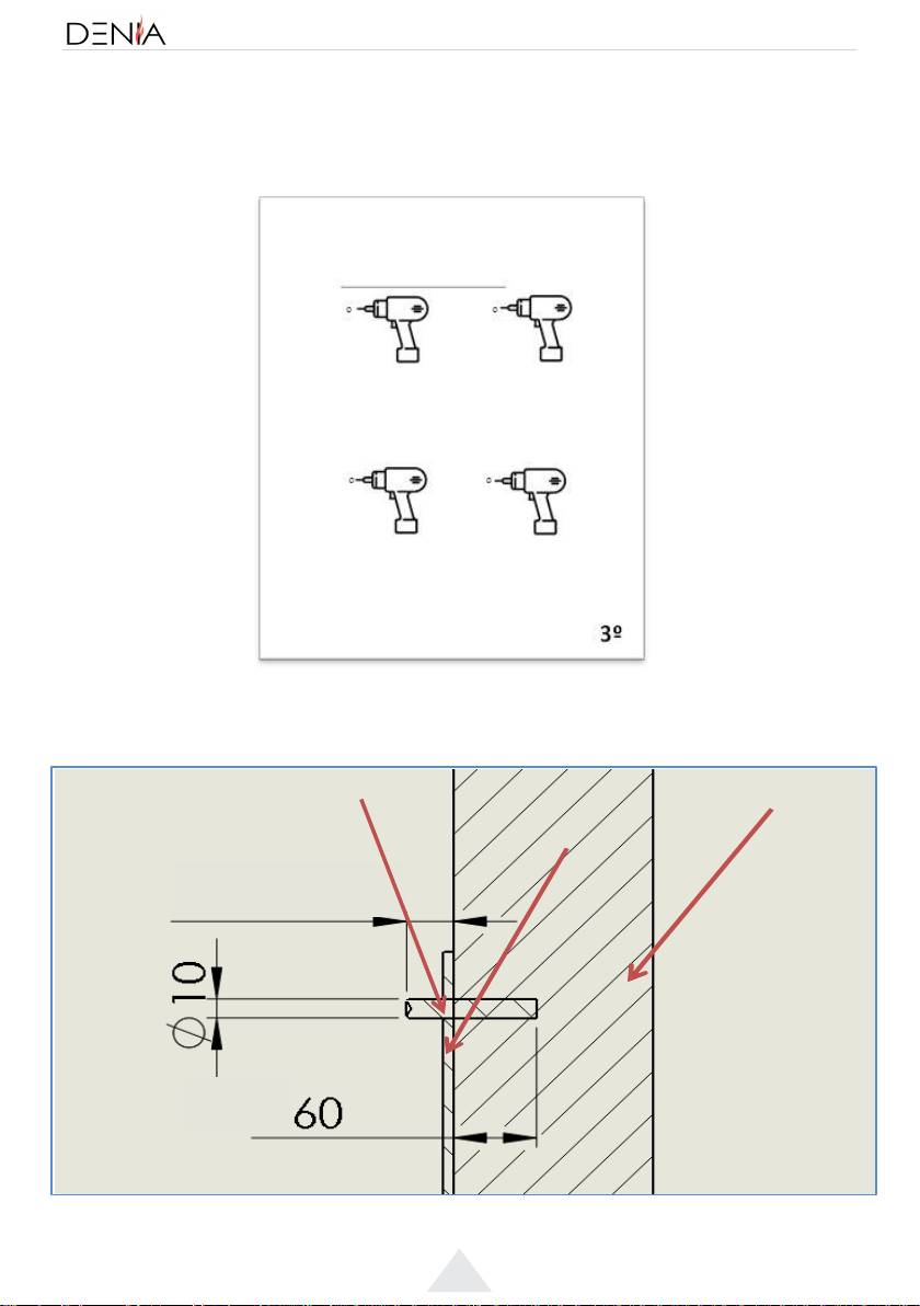
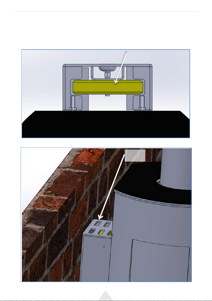
If you wish to install the stove with the external air intake, take this into the
consideration before fastening it on the wall. Illustration 4 shows the levels and
measures to be followed in order to make a hole on the wall. The diameter of the
external air intake pipe is 80 mm, so it´s recommendable to use a connection pipe
of wider diameter.
Plan of external air intake
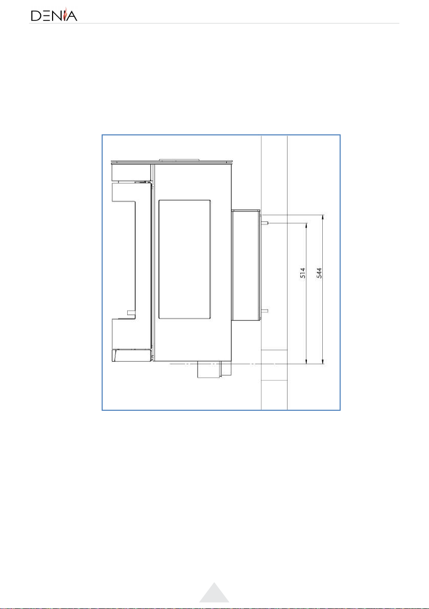
4) In order to hang the stove assure that the holes of back part of the stove meet the
tabs of the bracket by moving the stove in perpendicular direction to the wall
(movement n°1). When the pieces meet, leave the stove to ‘’fall down”, to make sure
that the tabs fully enter the holes (movement n° 2).

Illustration5
Illustration6.
(1º)
(2º)
Movements to fit in the stove
Final position of the stove properly fitted

8
Ilustración 7.
Ilustración 8.
Nut
2
1
1º
2º
5) The stove has a regulating device (piece n°13) to adjust the inclination of the stove.
You need a metric key n°12 to handle this device shown on the illustration n°7.
Location of the regulating service
Firstly, remove the external nut (Nut 1). After that calibrate the stove using the
internal nut (Nut 2):
In clockwise direction to lift the stove
In counter clockwise direction to lower the stove
Fasten the external nut (Nut 1) after calibration of the stove.
Nut
Calibration of the stove

9
Illustration9.
Vermiculite
Illustration10.
Cover
6) When the stove is properly placed and fastened on the wall, we can unpacked the
Piece nº 6 and place it inside the Piece nº 4. While placing it, make sure it fits into the
slots of Piece nº 7 and it has central position. After that place the Piece nº 5 above
the bracket of the stove. Make sure that any protrusions stay inside the piece
(Illustration 9).
Positioning of vermiculite
Positioning of the cover
Mod.
LINZ WALL

Fixing rod M10
Wall bracket
Nut M10
Stove bracket
Bracket cover
Vermiculite
Vermiculite slot
Vermiculite block
Regulator
Regulator block
Air intake
COMPONENT
LINZ WALL

11
Ilustración 1. Plano General
INSTRUCCIONES DE INSTALACIÓN DE LINZ WALL
Mod.
LINZ WALL

12
1) Se recomienda que la parte superior de la estufa en su posición final esté a
aproximadamente 1,10 mdel suelo. Para ello, la parte superior del soporte de pared
debe estar a del suelo. Marcamos la pared a esa altura y presentamos la
placa de pared (paso 1º). Con un nivel se comprueba que está horizontal y marcamos
en la pared los cuatro orificios (paso 2º).
º º
º º
90 cm
90 cm

13
Pared
Soporte de
pared
Anclaje
Ilustración 2. Plano de anclaje
20 mm
º º
º º
2) Una vez tengamos marcados los puntos, realizamos los taladros con una broca de
métrica 12 con una profundidad de 60 mm (paso 3º). Seguidamente se rellena con la
fijación química (no incluida) y se introduce la cánula. Después se rellena la cánula con
más fijación química y por inserta el anclaje de 10 mm de diámetro.
El anclaje debe sobresalir de la pared 20 mm y debe llegar al fondo de la cánula.
En la parte sobresaliente de los anclajes irá colgado el soporte de pared (Pieza Nº2).
Mod.
LINZ WALL

14
3) Con los espárragos de sujeción bien fijados, colocamos la Pieza Nº2 sobre la pared
haciendo coincidir los taladros de la pieza con los anclajes y la fijamos con cuatro
tuercas de la misma métrica que éstos.
Ilustración 3. Fijación apoyo pared

15
La siguiente consideración a tener en cuenta es abrir una abertura para la toma de aire
exterior (este paso es únicamente necesario si el cliente quiere conectar el aparato al
exterior), fijándonos en la Ilustración 4 tenemos las cotas de referencia a las cuales
tenemos que realizar el hueco en la pared. El diámetro de la toma exterior es de 80
mm por lo que se recomienda utilizar un tubo de mayor diámetro.
Ilustración 4. Plano toma aire exterior
4) Para colgar la estufa sobre el soporte de la pared hay que hacer coincidir las pestañas de
la placa con los orificios de la parte trasera de la estufa con un movimiento
perpendicular a la pared (movimiento 1º). Una vez en esta posición, hay que dejar caer
la estufa sobre las pestañas (movimiento 2º), asegurándose de que entra por dentro.
Mod.
LINZ WALL

Ilustración 5 Movimientos para encajar la estufa
Ilustración 6. Posición final de la estufa encajada
(1º)
(2º)

17
5) El aparato dispone de un regulador (Pieza Nº 13) la cual le va a permitir regular la
inclinación del aparato. Se necesita una llave de métrica 12 para llevar a cabo esta
operación actuando sobre esta pieza señalada en la Ilustración 7.
Ilustración 7. Localización Regulador
Lo primero es dejar libre la tuerca exterior (Tuerca 1). Seguidamente hay que hacer la
calibración con la tuerca interior (Tuerca 2):
En sentido de las agujas del reloj para levantar el aparato
En sentido contrario a las agujas del reloj para bajar el aparato
Por último, se debe apretar la tuerca exterior (Tuerca 1) para dejar fijo el sistema de
regulación.
Ilustración 8. Procedimiento de calibración
Tuerca 2
1º
2º
Tuerca 1
Mod.
LINZ WALL

18
6) Colocada y fijada la estufa correctamente, desembalamos la Pieza Nº 6, y la
dentro de la Pieza Nº 4, haciéndola pasar entre las ranuras de la pieza Nº 7 dejándola
centrada, realizada esta operación colocamos la Pieza Nº 5 sobre la parte superior del
apoyo estufa, haciendo que los salientes queden por dentro de la pieza (Ilustración 9).
Ilustración 9. Colocación vermiculita
Vermiculita
Ilustración 10. Colocación tapa
Tapa

11
Mod.
ELYPS WALL
LINZ WALL

20
Illustration1. Plan général
INSTRUCTIONS D' INSTALATION LINZ WALL
Table of contents
Languages:
Other DENIA Wood Stove manuals
Popular Wood Stove manuals by other brands

RAIS
RAIS attika NEXO 100 GAS installation guide

WoodPro
WoodPro WS-TS-1500 owner's manual

Contura
Contura C 586W installation instructions

Palazzetti
Palazzetti EVA GENERAL INFORMATION - WARNINGS - INSTALLATION - MAINTENANCE

Lopi
Lopi 1250 Republic owner's manual

Panadero
Panadero CAPRI 3V Usage and maintenance instructions