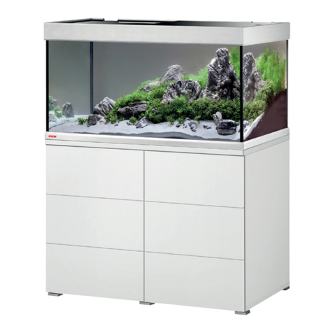
Denios Bio.x B200 User manual

Cleaning Table
USERS MANUAL 01/2010
175733_BA_EN_006

bio.x B200 Page 2 of 12 01/2010
172236, 172292, 176074
Index
1. Safety instructions ....................................................................................................... 3
2. Technical data............................................................................................................... 3
3. Product description...................................................................................................... 4
3.1 Layout ............................................................................................................................ 4
3.2 Intended use .................................................................................................................. 5
3.3 How it works................................................................................................................... 5
4. Initial Operation ............................................................................................................ 5
4.1 Filling with the cleaning fluid .......................................................................................... 5
4.2 Electrical connection ...................................................................................................... 5
5. Operation....................................................................................................................... 6
6. Maintenance.................................................................................................................. 6
7. Optional Accessories................................................................................................... 8
8. Notes regarding disposal............................................................................................. 8
9. Faults............................................................................................................................. 9
10. Connection Diagram................................................................................................... 10
11. EC Declaration of Conformity.................................................................................... 11

bio.x B200 Page 3 of 12 01/2010
1. Safety instructions
This unit can only be used safely if you read this user manual carefully and strictly follow the instruc-
tions it contains.
The equipment must be set up on a suitable stable, level surface.
Please note the application- and warning messages on the label of the detergend. wrong use could
cause damage to material and health.
Contact to the detergend could cause skin irritation. when operate the system please always ware
safety gloves, safety glasses and protective clothing.
Please professional dispose used detergend
The mains supply connection has to be in accordance with the corresponding regulations (VDE 0100 - As-
sociation of German Electricians). For safety reasons the equipment must be only operated, if a Residual
Current protective Device (RCD) with a release current of 30 mA is connected upstream.
This must be checked by a qualified electrician.
In accordance with the German BGV A3 electrical equipment has to be examined in regular inter-
vals.
Detergents which contain highly flammable substances must not be used. Use only detergents ap-
proved by DENIOS for this unit.
2. Technical data
Dimensions 890 x 750 x 1155 mm
Net weight 45 kg
Power consumption max. 660 W
Electrical connection 1/N/PE 230V∼, protection category 1
Pre-fusing 10 A
Work surface height 950 mm
Load capacity 100 kg
Tank LDPE
Maximum fill capacity approx. 80 l
Minimum fill capacity 40 l
Usable work surface 760 x 560 mm
Heater 600 W
Level switch Minimum fill level (approx. 40 l)
Operating temperature Set at 41°C in the factory
Pump, flow rate 4l/min
172236, 172292, 176074

bio.x B200 Page 4 of 12 01/2010
3. Product description
3.1 Layout
Item Description Mat.
No. Item Description Mat. No.
A ON-OFF switch pump - 7 Draining device set 175373
B Display level - 8 Technical components set 175340
1 Sump -
8.1 heater 186596
2 Stand top - 8.2 Pump 134979
3 Stand top seal 175033 8.3 Aerator 135310
4 600 µm filter screen 135256 8.4 Level switch 174951
5 Coarse filter 135255
6 Cleaning unit set 175370 9 Filter set (optional) 172237
6.1
Ball valve 135279
9.1
Filter insert
(central support bracket and
nylon filter)
150043
6.2 Wash brush 135277 9.2 O-ring 150609
A
B
172236, 172292, 176074

bio.x B200 Page 5 of 12 01/2010
3.2 Intended use
The bio.x parts cleaning unit is used to clean oil and grease from work pieces in an efficient, environmen-
tally sustainable way using exclusively cleaning fluids authorised by DENIOS.
Other detergents such as degreasers or alkali cleaning agents must not be used!
Solvents, disinfectants, alkali or acidic fluids, carburettor and diesel fuels or turpentine must not be
poured into the appliance.
3.3 How it works
A pump feeds the cleaning fluid to the three-way stopcock and the cleaning brush. An air pump ensures a
good supply of oxygen for the cleaning fluid.
Air pump and heater are running continuously.
The heating is controlled via an integrated sensor.
When connected to power supply, air pump and heater are switched on.
4. Initial Operation
After removing the packaging, check the unit casing and operating components for any possible damage
caused in transit. If such damage is found, do not connect the unit to the mains. Report damage immediately
to the carrier who delivered the unit and to DENIOS AG at the service number indicated above. The original
packaging should be kept.
Place the unit in a dry, stable location as required.
The floor must be level. If necessary, level out any uneven surfaces with suitable shimming material.
4.1 Filling with the cleaning fluid
The unit can be opened at the side for servicing or to fill the tank with fresh
detergent. To do so, lift up the right-hand side of the unit top and prop it up
using the bar you can find inside.
Maintenance position of
stand top (aperture angle
a
pp
rox. 50°
)
The cleaning fluid bio.x is available as ready mix or as concentrate.
Fill the ready mix, 4 canisters per 20l = 80l, or the concentrate, 4 canisters
per 5l added to 70l of water into the tank. (please note the maximum level
marking)
4.2 Electrical connection
The unit is connected to the customer's mains supply via the power cable
and plug.
Mains voltage: The voltage of the power source has to comply with the
details on the identification place of the appliance
Warning: The mains supply must be fitted with a residual current protective device in accordance with
DIN VDE (Association of German Electricians) 0100! (See section 2)
After connected the unit to the mains air pump and heater are switched on. The warming-up process can take
up to 5 hours, depending on the initial temperature. The operating temperature is set at 41°C in the factory
and can not be changed. You can measure the current temperature of the cleaning fluid with a standard
thermometer. After reaching the operating temperature parts cleaning unit is ready for use.
172236, 172292, 176074

bio.x B200 Page 6 of 12 01/2010
5. Operation
Place the parts to be cleaned in the cleaning basin.
Do not exceed the maximum load of 100 kg!
Activate the ball valve (6.1.) Press the on/off switch (A). The parts are cleaned with a wash brush.
The dirty detergent runs back into the tank via the middle plug outlet where special micro-organisms remove
oil and grease contaminants.
Note:
When interrupting work, do not disconnect the unit from the mains, so the detergent remains warm. The micro-
organisms in the detergent require heat and oxygen to degrade the oil and grease. For this reason, the heat-
ing system maintains the temperature of the detergent at 41º C and an aerator ensures oxygen is permanently
fed to the micro-organisms. If the unit is switched off, or it breaks down for a long period of time, the micro-
organisms become inactive.
6. Maintenance
Warning!
Before starting work on the cleaning table fixtures unplug from the mains!
Test the equipment to ensure the power is off!
The unit can be opened at the side for servicing or to fill the tank with fresh detergent (see point 4.1).
Fill level
Check the fill level regularly so you can refill to make up for any losses through evaporation and removal. The
mark on the back wall of the container shows the maximum fill length. If the minimum fill level (approx .23 cm
below the maximum level) is reached, the pump and the heating system switch off automatically for safety
reasons. The red control display (B) lights up. Please refill enough cleaning fluid so that the optimum fill level
is reached and the maximum mark is not exceeded. The message will disappear once there is enough deter-
gent in the tank.
Additive
More additive should be put in every 6 months to replenish the micro-organisms.
After refilling, the detergent must be left to stand for 24 hours so that the micro-organisms can become active.
It is therefore recommended to refill with the additive before a weekend.
Filter
The washstand is equipped with two filters as standard. A stainless steel perforated filter on the washstand
surface and a synthetic filter for impurities underneath. It is recommended to clean these filters on a daily
basis. To do so, remove the filters from the unit and rinse with water.
172236, 172292, 176074

bio.x B200 Page 7 of 12 01/2010
Fine filter (9)
The optional fine filter, which can be fitted on the left-hand side of the unit,
should be checked weekly and cleaned if necessary. Release the filter cover
by turning it anti-clockwise. Remove the filter cartridge (9.1) and rinse it thor-
oughly under running water, or replace it with a new cartridge. Reinsert the car-
tridge and screw the casing firmly back into place. Ensure the seal is in the cor-
rect position.
Safety temperature limiter
In case of overheating the cleaning fluid, the power supply will be interrupted by the safety tempera-
ture limiter. To start again press red button. (see photo)
Cleaning fluid
The cleaning fluid has to be replaced if
- there is a significant fall in the cleaning performance
- when checking the fill level there are notable sediment deposits on the floor of the tank
Use the draining device (7) to drain the dirty fluid. Then the tank has to be freed from any sediment residue.
Please follow the same process when inserting the new fluid as for the initial operation.
Refill items
Accessories Description Item number
Bio-Power cleaning fluid 20-litre canister 175715
Bio-Power cleaning fluid 200-litre drum 169787
Additive for oil and grease degradation 100g can for 100 l detergent 168625
Set (cleaner and additive) for initial filling
and refills
4 x 20-litre canisters of Bio-Power cleaning fluid
100 g can of additives 173135
Cleaning fluid bio.x 20-litre canister 130032
Cleaning fluid bio.x 200-litre drum 161524
Replacement parts (see also product description page 4)
Description Item number
Filter insert for fine filter (optional)
Central support bracket and nylon filter
150043
172236, 172292, 176074

bio.x B200 Page 8 of 12 01/2010
7. Optional Accessories
Accessories Description Item number
Residual current device
adapter
Adapter for fuse protection for the appliance
Release current: 30 mA,
Protection category: IP44
177335
Protective gloves
(1 pair)
with extra long gauntlet, internally padded with cotton fabric
Length: 640mm
Size: 10
EN388: 4121
Resistance: good protection against detergents, alkali, oils and
greases
163613
Filter screen type 454
Fineness 80 μm
Can be used as an alternative for filter screen (12) 161047
Perforated metal insert To protect the work surface of the cleaning table
Makes it possible to work without tilting
172239
Dolly For portable use of the parts cleaning unit 172240
Curved wash brush For cleaning curved edges, prevents signs of fatigue when working for a
long time.
172560
Stainless steel brush To remove heavily crusted dirt from insensitive parts 173926
Wet vacuum cleaner
Type SV 6.16 To completely empty the tank, also suitable for sludge 123224
Flexible hose The flexible hose with flat nozzle guarantees simple rinsing of the parts. 135289
Lid 174288
8. Notes regarding disposal
Detergent
The relevant waste code number for a contaminated substance depends on the type of dirt removed and not
on the type of detergent. The applicable waste code number can be found in the European Waste Catalogue.
Contaminated substances can often be disposed of as a water and oil mixture in other hydrous systems.
Unused fluids can be fed into waste water treatment plant while taking into account local regulations regarding
wastewater disposal.
Appliance
According to the electronic and electrical appliance regulations, owners of disused appliances
are legally required to dispose of such items separately. Please help to protect the
environment by not disposing of disused appliances with household waste.
172236, 172292, 176074

bio.x B200 Page 9 of 12 01/2010
172236, 172292, 176074
9. Faults
Warning! Before starting work on the cleaning table fixtures, switch off the electrics and unplug from the
mains! Test the equipment to ensure the power is off!
Fault Cause Solution
Detergent cold, heating sys-
tem not working
1. The heater is not connected
properly or is faulty;
2. Fuse faulty
3. Safety temperature limiter has
been triggered
1. Check the electrical connections of the
heater. If necessary replace the heater
2. Replace fuse (11).
3. Check the appliance, remove the
cause for the overheating, press the
button for the safety temperature lim-
iter (10)
Wash pump not working
1. The wash pump is not con-
nected properly or is faulty;
2. Fuse faulty
1. Check the electrical connections of the
wash pump. If necessary replace the
wash pump
2. Replace fuse (13).
Aerator not working
1. The aerator is not connected or
is faulty
2. Fuse faulty
1. Check the electrical connections of the
aerator. If necessary replace the aera-
tor
2. Replace fuse (12).
Level switch not working
1. The level switch is not con-
nected properly
2. The level switch is faulty. Short-
circuit in level switch
1. Check the electrical connection of the
level switch.
2. Replace level switch
Heating system and wash
pump not working. Level
display flashing
Fill level fallen below minimum
level Refill with detergent
Level display flashing, al-
though the appliance is filled
sufficiently
The ball in the float switch is stuck Lift the float switch (8.4) briefly
Note:
To check the fuses the technical components (Item 8) can be removed completely from the appliance after
pulling the hose from the ball valve and loosening the tapping screws.
If you have a more complex fault please contact our service technician.

bio.x B200 Page 10 of 12 01/2010
10.Connection Diagram
5x20mm
5A T
5x20mm
0,1A M
5x20mm
1A M
Power line 230 VAC
heater
Air pump
pump
Flopat switch
Indicator light
Pump switch
Indicator light
Pump switch
Float switch
172236, 172292, 176074

bio.x B200 Page 11 of 12 01/2010
11.EC Declaration of Conformity
EC Declaration of Conformity
Herewith we, the DENIOS AG, Dehmer Straße 58-66, D 32549 Bad Oeynhausen, declare that the parts
cleaner B 200 complies with following guidelines:
EC Directives
2006/42/EC
2004/108/EC
Harmonised standards applied
EN 349
EN 12100 -1,-2
EN 60204-1
172236, 172292, 176074
EN 12981-1;-2.
Person responsible for documentation DENIOS AG, AG, 04.01.2010
Mr. Dr. Ing. R. Adenstedt Theodor Breucker
Head of engineering - Board of governors –
Address see below
DENIOS AG
Dehmer Straße 58-66
32549 Bad Oeynhausen
Tel.: +49 (0)5731 7 53 – 0
Fax: +49 (0)5731 7 53 – 197
You`ll find your local partner on our InterNet side www.denios.com

bio.x B200 Page 12 of 12 01/2010
172236, 172292, 176074
Other manuals for Bio.x B200
1
Table of contents


