4. Use the “Kent J-42188-B” tool to separate
upper ball joint taper.
CAUTION: Do not DAMAGE CV boot when lower-
ing, and closely watch ABS cable as well.
STEP 1: (Continued)
STEP 2A: For 1.75-2” of Lift
STEP 2B: For 2.25-2.5” of Lift (Recommended)
12. Reinstall strut with selected shims installed on
top. Prying down on the sway bar is required in the
same procedure as Step 10. Hand tighten three new
supplied short flanged nuts onto exposed threads on
top strut mount.
NOTICE: Repeat procedure 7-12 on both sides of the vehicle
before continuing.
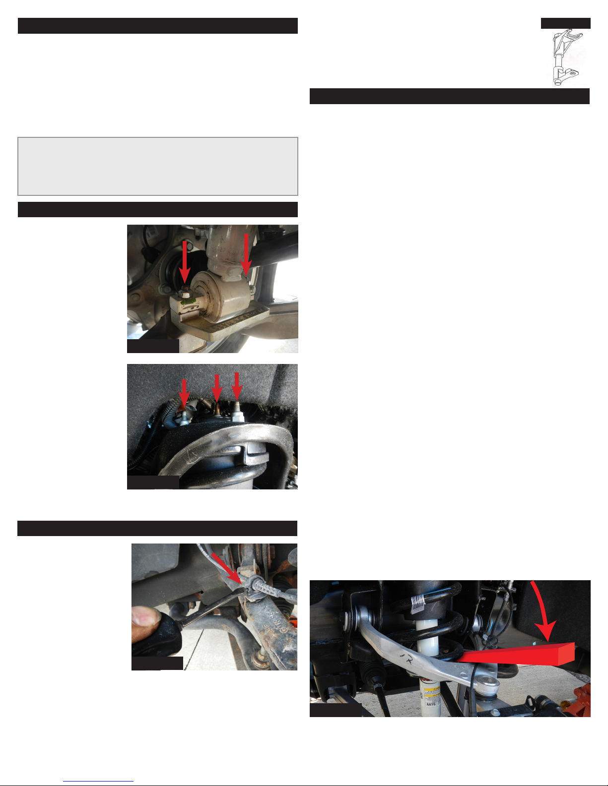
1. Pry down on sway
bar with pry bar
which will low-
er the control
arm allowing for
installation of
the Strut Mount
Extender.
“SUSPENSIONMAXX”
side facing up.
2. Align mount-
ing holes install
supplied bolt,
washers and nuts.
Torque to 35/lbs
(FIG 2A-1)
3. Torque 3 upper
strut mount nuts
to 25/lbs.
(FIG 2A-2) Reinstall wire loom clips.
1. Lightly support
lower A-arm with
bottle jack or foot
jack
2. Unlock the ABS
wire loom clip,
allowing the ABS
wire to be free
from the clip.
(FIG 2B-1)
3. Remove ball joint nut with 18mm wrench
1. NOTICE: For 1.75-2” you do not need to disconnect up-
per ball joint to complete installation. For customers li
their vehicle 2.25-2.5” disconnecting the upper ball joint
is required.
FIG. 2A-1
FIG. 2A-2
Kent J-42188-B
FIG. 2B-1
STEP 2B: For 2.25-2.5” of Lift (Alternative Method)
NOTICE: We recommend the procedure above. Use the
alternative method at your own risk.
1. Lightly support lower A-arm with bottle jack or foot
jack
2. Unlock the ABS wire loom clip, allowing the ABS wire
to be free from the clip. (FIG 2B-1)
3. Loosen upper ball joint nut with 18mm wrench,
3-5 threads, until an air gap is achieved and the nut
spins freely. Pry downward on the suspension, strike
the knuckle with a brass dri and hammer to shock
the taper and unseat the ball joint.
4. Pry down on sway bar with pry bar which will lower
the control arm allowing for installation of the Strut
Mount Extender. “SUSPENSIONMAXX” side facing up.
NOTICE: Use EXTREME Caution during the step above,
closely monitor ABS wire and CV Axel clearances to prevent
damage.
5. Align mounting holes install supplied bolt, washers
and nuts. Torque to 35/lbs (FIG 2A-1)
6. Reconnect ball-joint. Apply pressure by pumping the
bottle jack under the lower control arm.
7. Raise the lower A-Arm with the bottle jack on the
outermost point on the control arm.
NOTICE: Use caution when jacking under the lower control
arm as it may cause the vehicle to raise o jack stands.
8. Pry downward on the upper control arm realigning
the upper ball joint with the knuckle. Thread on
upper ball joint nut.
NOTICE: Prying downward on the upper A-Arm will seat
taper and hold the stud from rotating as you tighten the
18mm ball joint nut. Some ball joint tapers have Allen hex
to hold ball joint stud while seating the taper.
Torque to 37/lbs plus an additional 1/4 turn.
(FIG 2A-2)
FIG. 2B-2