Denison Hydraulics Goldcup M11 Series User manual
DENISON HYDRAULICS
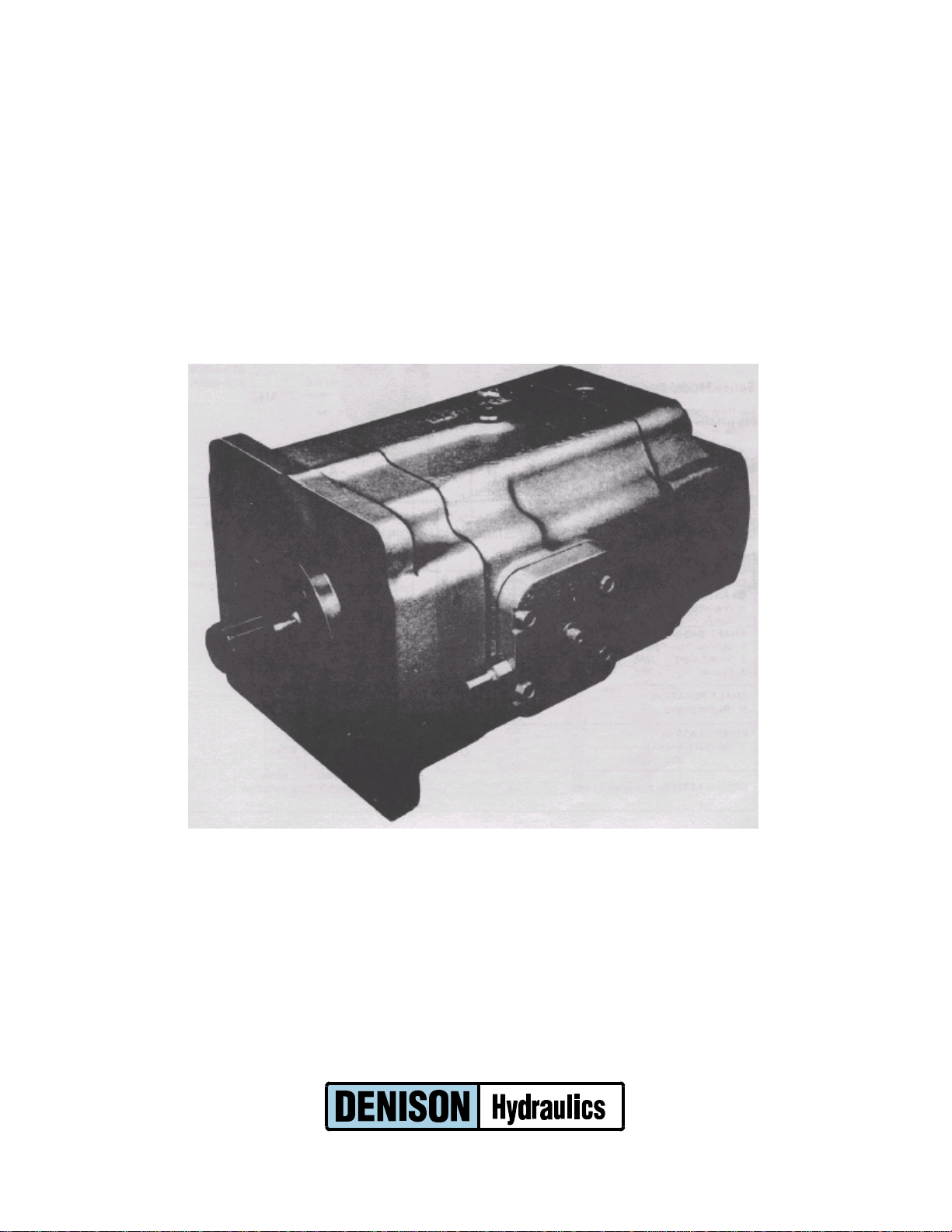
Axial Piston Motor
Variable Displacement
Installation and Overhaul Instructions
Goldcup Series M11
Goldcup Series M14
SVM-M11/M14-D
Revised 7/03
www.comoso.com

TABLE OF CONTENTS
PAGE
Introduction----------------------------------------------------------------------------------------------------------------------------------- 3
Installation
Mounting--------------------------------------------------------------------------------------------------------------------------------------- 4
Piping------------------------------------------------------------------------------------------------------------------------------------------- 4
Fluid recommendation & maintenance------------------------------------------------------------------------------------------------- 4
Start-Up Procedures------------------------------------------------------------------------------------------------------------------------ 4
Table II: Troubleshooting------------------------------------------------------------------------------------------------------------------ 6
Rework limits--------------------------------------------------------------------------------------------------------------------------------- 7
Disassembly
Controls---------------------------------------------------------------------------------------------------------------------------------------- 8
Barrel holddown------------------------------------------------------------------------------------------------------------------------------ 8
Port block-------------------------------------------------------------------------------------------------------------------------------------- 8
Barrel and holddown shaft---------------------------------------------------------------------------------------------------------------- 8
Drive shaft------------------------------------------------------------------------------------------------------------------------------------- 8
Housing---------------------------------------------------------------------------------------------------------------------------------------- 8
Rocker cam and control stroking assembly------------------------------------------------------------------------------------------- 9
Assembly
Drive shaft assembly----------------------------------------------------------------------------------------------------------------------- 10
Rocker cam and stroking assembly---------------------------------------------------------------------------------------------------- 11
Vane seal cartridges------------------------------------------------------------------------------------------------------------------------ 11
Control chambers---------------------------------------------------------------------------------------------------------------------------- 11
Servo assembly------------------------------------------------------------------------------------------------------------------------------ 12
Piston and shoe assembly---------------------------------------------------------------------------------------------------------------- 12
Barrel and holddown shaft assembly--------------------------------------------------------------------------------------------------- 15
Barrel and stroking assembly to mounting flange----------------------------------------------------------------------------------- 16
Housing assembly--------------------------------------------------------------------------------------------------------------------------- 17
Housing assembly installation------------------------------------------------------------------------------------------------------------ 18
Port block installation----------------------------------------------------------------------------------------------------------------------- 19
Barrel holddown----------------------------------------------------------------------------------------------------------------------------- 19
Shaft assembly------------------------------------------------------------------------------------------------------------------------------- 22
Seal assembly-------------------------------------------------------------------------------------------------------------------------------- 22
Counterbalance servo stem assembly------------------------------------------------------------------------------------------------- 22
Control cover assemblies----------------------------------------------------------------------------------------------------------------- 23
Shuttle valve assembly-------------------------------------------------------------------------------------------------------------------- 25
Ordering code-------------------------------------------------------------------------------------------------------------------------------- 27-28
See catalog S1-2AM-7501-A for all available kits.
The product information, specifications, and descriptions contained in this publication have been compiled for the use and
convenience of our customers from information furnished by the manufacturer; and we can not, and do not, accept any responsibility
for the accuracy or correctness of any description, calculation, specification, or information contained herein. No such description,
calculation, specification, or information regarding the products being sold has been made part of the basis of the bargain, nor has
same created or amounted to an express warranty that the products would conform thereto. We are selling the goods and
merchandise illustrated and described on this publication on an “as is” basis, and disclaim any implied warranty,
including any warranty of merchantability or warranty of fitness for any particular purpose whatsoever, with respect to the
goods and merchandise sold. All manufacturer warranties shall be passed on to our customers, but we shall not be responsible
for special, indirect, incidental, or consequential damages resulting from the use of any of the products or information contained or
described on this publication. Further, we reserve the right to revise or otherwise make product improvements at any time without
notification.
2
www.comoso.com
INTRODUCTION
GENERAL
The Denison Goldcup series 11 and 14 axial piston motors feature advanced design concepts which are
time proven and aid in providing smooth controlled power in a compact package. The instructions
contained in this manual cover installation, maintenance and repair of the Goldcup series motors. Before
proceeding with the disassembly or reassembly of any unit, study this manual to become familiar with the
basic fit and function of the internal parts. Refer to the troubleshooting chart when diagnosing any
malfunction. Disassemble only as far as necessary to replace or repair any worn parts.
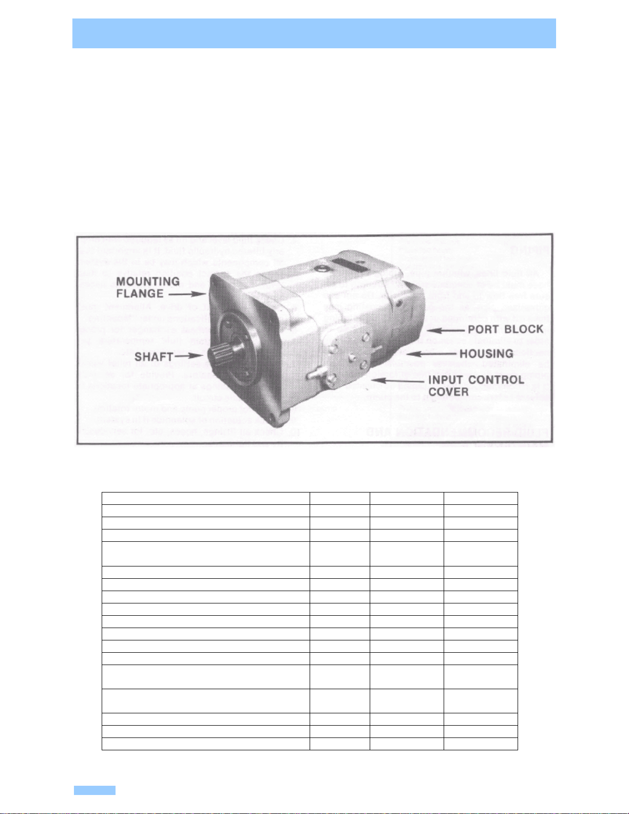
DESCRIPTION
The Goldcup series axial piston motors feature the use of a rocker cam and cradle stroking control to vary
displacement. This allows a compact unit while retaining the flow capacity of a larger motor, as well as
reducing wear and speeding control response. A vane actuator with a rotary servo operates the stroking
control thus varying flow.
Table 1
TYPICAL CHARACTERISTICS
Specification Term Goldcup 11 Goldcup 14
Displacement at max. angle In. 3/rev 11 14
Pressure Ports A or B max. continuous PSI 5000 5000
Intermittent (not to exceed 6 sec/min) PSI 6000 6000
Mounting Standard SAE 4-Bolt
fluid connections, Ports A & B SAE-ESAE-E
4-Bolt Pad for 6000 PSI Split Flange SAE –1 1/2” SAE –1 1/2”
Speed, max. continuous @ full displ. RPM 2400 2400
Speed, max. continuous @ 50% displ. RPM 2800 2800
Flow, Theor. max @ 100 RPM GPM 4.75 6.06
Flow, Theor. max @ 2400 RPM GPM 114 145
Torque Theor. max. per 100 PSI IN# 175 222
Torque Theor. max. @ 5000 PSI IN# 8750 11,100
Torque Theor. max @ 6000 PSI IN# 10,500 13,300
Power Theor. max @ 5000 PSI per 100
RPM HP 13.8 17.6
Power Theor. max @ 5000 PSI per 2400
RPM HP 330 425
Efficiency Torque approx.—stalled % theor. 81 81
-- running 93 93
Pkg. motor variable displ. 2AO control lbs. 300 300
3
www.comoso.com

INSTALLATION
MOUNTING
The mounting hub and four bolt mounting flange conform to SAE-E configuration. The motor must be
mounted on a base or bracket of sufficient strength to support the unit without flexing or movement. It is
recommended that a dial indicator be used when checking alignment. The concentricity of the pump
shaft and driven load shaft must not exceed .010” T.I.R. and ideally should be .006”-.008” T.I.R.
maximum. Shaft concentricity is particularly important if the motor is rigidly connected without a flexible
coupling or a coupling that allows only for minor misalignment.
PIPING
All fluid lines, whether pipe, tubing or flexible hose must be of adequate size and strength to assure free
flow to and from the motor. Do not use galvanized pipe, as the galvanized coating may flake off with
continued use. If rigid pipe or tubing is used, the workmanship must be accurate in order to eliminate
strain on the pump or fluid connections. Sharp bends, elbows or reducers should be eliminated wherever
possible. All system piping must be clean and free of foreign material. It is recommended that all piping
be cleaned with solvent before connecting it to the pump.
FLUID RECOMMENDATION AND MAINTENANCE
Satisfactory operation depends on many factors, the most important of which is the selection of the
proper hydraulic fluid and its subsequent maintenance. Select only high quality fluids which conform to
Denison HF-0 and HF-1 specifications. If in doubt concerning the correct fluid for use, contact a Denison
sales representative. Efficient filtration is essential and cannot be overemphasized. Fluid cleanliness
must conform to NAS class 8 or 9, 15 micron and under. Effective continuous use of 10 micron filters will
assure compliance to this standard. Operating temperature is determined by the viscosity characteristics
of the fluid selected. Because high operating temperatures degrade seals, reduce the service life of the
fluid and pose potential hazards, fluid temperatures should not exceed 180°F at the case drain.
START UP PROCEDURE AND INSTALLATION
1. Read and understand the equipment manual before installation of the Goldcup motor. Identify
system components (relief valves, solenoids, etc.) and their function is essential to satisfactory
operation.
2. Visually inspect system components. Their proper placement and function is essential to
satisfactory operation.
3. Check reservoir for cleanliness per instructions outlined under “Fluid Recommendation and
Maintenance”. Drain and/or filter system fluid as required.
4. Check fluid level and fill as required with properly filtered hydraulic fluid. It is important that all
components which may be in the system are in the correct position relative to fluid level. Fill
pump and motor cases as necessary.
5. Check alignment of drive. Alignment must conform to specifications under “Mounting”.
6. Check oil cooler/heat exchanger for proper operation. Maintain fluid temperature per
recommendations under “Fluid”. etc.
7. Reduce pressure settings of all relief valves and/or compensators. Provide for accurate pressure
readings at appropriate locations in the hydraulic circuit.
8. Check for proper pump and motor rotation.
9. Check actuation of solenoids if in system.
10. Check all fittings, hoses, etc. for serviceability and tightness.
11. Start pump drive at reduced speed if possible and make sure units fill properly.
4
www.comoso.com

INSTALLATION (continued)
12. Cycle unloaded equipment at low speed and pressure. Observe for proper function of all
components.
13. Bleed system of any trapped air. Re-check fluid level and fill as necessary.
14. Gradually increase speed and pressure settings. Be alert for leaks, particularly in pump and
motor inlet lines, as these may cause cavitation and eventual pump failure.
15. Check for possible trouble indicated by changes in sounds, system shocks and air in fluid.
16. Equipment is now operational.
5www.comoso.com

TABLE II
TROUBLESHOOTING CHART
TROUBLE SHOOTING
Component problems and circuit problems are often inter-related. An improper circuit may operate with apparent success but will
cause failure of a particular component within it. The component failure is the effect, not the cause of the problem.
This general guide is offered to help in locating and eliminating the cause of problems by studying their effects.
EFFECT OF TROUBLE POSSIBLE CAUSE FAULT WHICH NEEDS REMEDY
Air in Fluid Leak in suction line
Leak at shaft seal
Low fluid level
Turbulent fluid
Return lines above fluid level
Gas leak from accumulator
Excessive pressure drop in the inlet line
from a pressurized reservoir
Suction line strainer acting as air trap
Cavitation in motor rotating group Fluid too cold
Fluid too viscous
Fluid too heavy
Shaft speed too high
Suction line too small
Suction line collapsed
Suction strainer too small
Suction strainer too dirty
Operating altitude too high
Boost or replenishment pressure too low
Replenishment flow too small for dynamic
conditions
Misaligned shaft Faulty installation
Distortion in mounting
Axial interference
Faulty coupling
Excessive overhung loads
Noisy Motor
Mechanical fault in pump Piston and shoe looseness or failure
Bearing failure
Incorrect port plate selection or index
Eroded or worn parts in the displacement
control
Air in fluid See aboveErosion on barrel ports and port plate Cavitation See above
Excessive loads Reduce pressure settings
Reduce speeds
Contaminant particles in fluid Improper filter maintenance
Filters too coarse
Introduction of dirty fluid to system
Reservoir openings
Reservoir breather
Improper line replacement
Improper fluid Fluid too thin or thick for operating
temperature range
Breakdown of fluid with
time/temperature/shearing effects
Incorrect additives in new fluid
Destruction of additive effectiveness with
chemical aging
Improper repair Incorrect parts
Incorrect procedures, dimensions,
finishes
High wear in motor
Unwanted water in fluid Condensation
Faulty breather, strainer
Heat exchanger leakage
Faulty clean-up practice
Water in make-up fluid
6
www.comoso.com
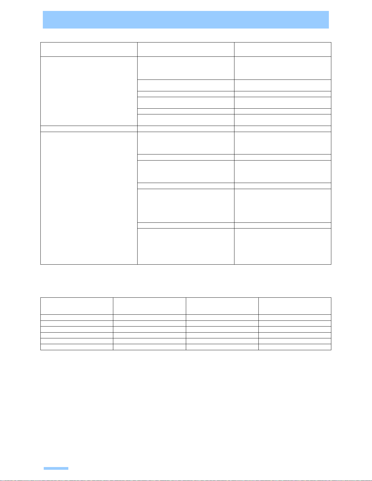
TABLE II
TROUBLESHOOTING CHART (continued)
EFFECT OF TROUBLE POSSIBLE CAUSE FAULT WHICH NEEDS REMEDY
Cogging load
Worn relief valve Mechanical considerations
Needed repairs
Servo pressure too low to maintain firm
control Increase pressure and check pressure
drop through servo filter
Excessive line capacitance (line volume,
line stretch, accumulator effects) Reduce line size or lengths. Eliminate
hose.
Pressure shocks
Barrel blow-off Re-check pump hold-down, rotating
group, drain pressure
Excessive motor leakage Re-check case drain flow and repair as
required
Fluid too thin
Improper assembly, port timing
Relief valve Set too low (compared to load or to
compensator)
Instability caused by back pressure, worn
parts
Heat exchanger Water turned off or too little flow
Water too hot
Fan clogged or restricted
Efficiency reduced by mud or scale
deposits
Intermittent hydraulic fluid flow
Heating of fluid
Reservoir Too little fluid
Entrained air in fluid
Improper baffles
Insulating air blanket that prevents heat
rejection
Heat pick-up from adjacent equipment
REWORK LIMITS OF WEAR PARTS
11 and 14 in.3 Original
Dimension Max. Rework
From Original
Dimension
Min. Dimension
After Rework
Port plate face .725/.715” .010” .705”
Cylinder barrel face 5,880” .010” 5.870”
Shoe retainer face .438/.437” .005” .432”
Piston shoe face (pocket) .020” .010” .010”
Creep plate face .251/.250” .010” .240”
Face plateNone Replace
7
www.comoso.com

UNIT DISASSEMBLY
The instructions contained in this section cover complete disassembly of the Denison Goldcup 11 and 14
motors. Disassemble only as far as necessary to replace or repair any worn parts. A clean bench or
similar surface capable of supporting unit should be used. After disassembly, internal parts should be
coated with a film of clean oil and protected from dirt and moisture. Excessive handling will cause parts
to rust and should be avoided.
CONTROLS (Figure 9)
1. Remove the four screws (15) from the side cover (17) and remove the input shear seal valve
assembly.
2. Remove the four screws (15) from the remaining side cover (16) and remove the counter balance
shear seal assembly.
3. Remove the two screws (13) and spacers (12). Remove the balance plate (11).
4. Remove the two screws (10) and balance stem (9).
BARREL HOLD-DOWN (Figure 8)
1. Remove retaining ring (3), end cover (5) and O-ring (4).
2. Remove cotter pin (6), hold-down nut (7), thrust washers (10), bearing (9) and seal ring (8).
PORT BLOCK (Figure 7)
1. Remove four screws (1) that secure the port block (2) to the housing (6).
2. Remove port block, gasket (5), port plate (4) and port plate pins (3).
CAUTION: The port plate may cling to the barrel face because of oil film. Do not allow the port plate to
fall and become damaged.
SHUTTLE VALVE (Figure 9)
1. Remove the screws (20) that secure the shuttle valve (18) to the port block.
2. Remove the shuttle valve and O-rings (19) from the port block. The valve is a complete assembly
and should not be disassembled.
BARREL AND HOLD-DOWN SHAFT (Figure 6)
1. Remove the face plate (2) and face plate pins (1) from face of the barrel assembly.
2. Remove barrel assembly by grasping hold-down shaft and lifting entire assembly from the
housing.
DRIVE SHAFT (Figure 9)
1. Remove four screws (8), gaskets (7), seal retainer (6), gasket (5), seal stop (4a), and stationary
part of shaft seal assembly (4). Refer to view of item 4.
2. Remove the carbon ring and the remainder of the shaft seal from the shaft.
3. Remove retaining ring (3), shaft and bearing assembly (1) and shim (2) if used.
HOUSING (Figure 6)
1. After removal of the shaft and bearing assembly, position the unit so that it rests on the mounting
flange.
2. Push the ends of pressure feed tubes away from the housing so as not to bend or damage them.
3. Lift the housing from the mounting flange. Remove the gasket and dowel pins. Mounting flange
must be driven off housing.
NOTE: Do not remove the roll pins or bearing from the housing unless bearing is damaged and
replacement is necessary.
8
www.comoso.com

UNIT DISASSEMBLY (continued)
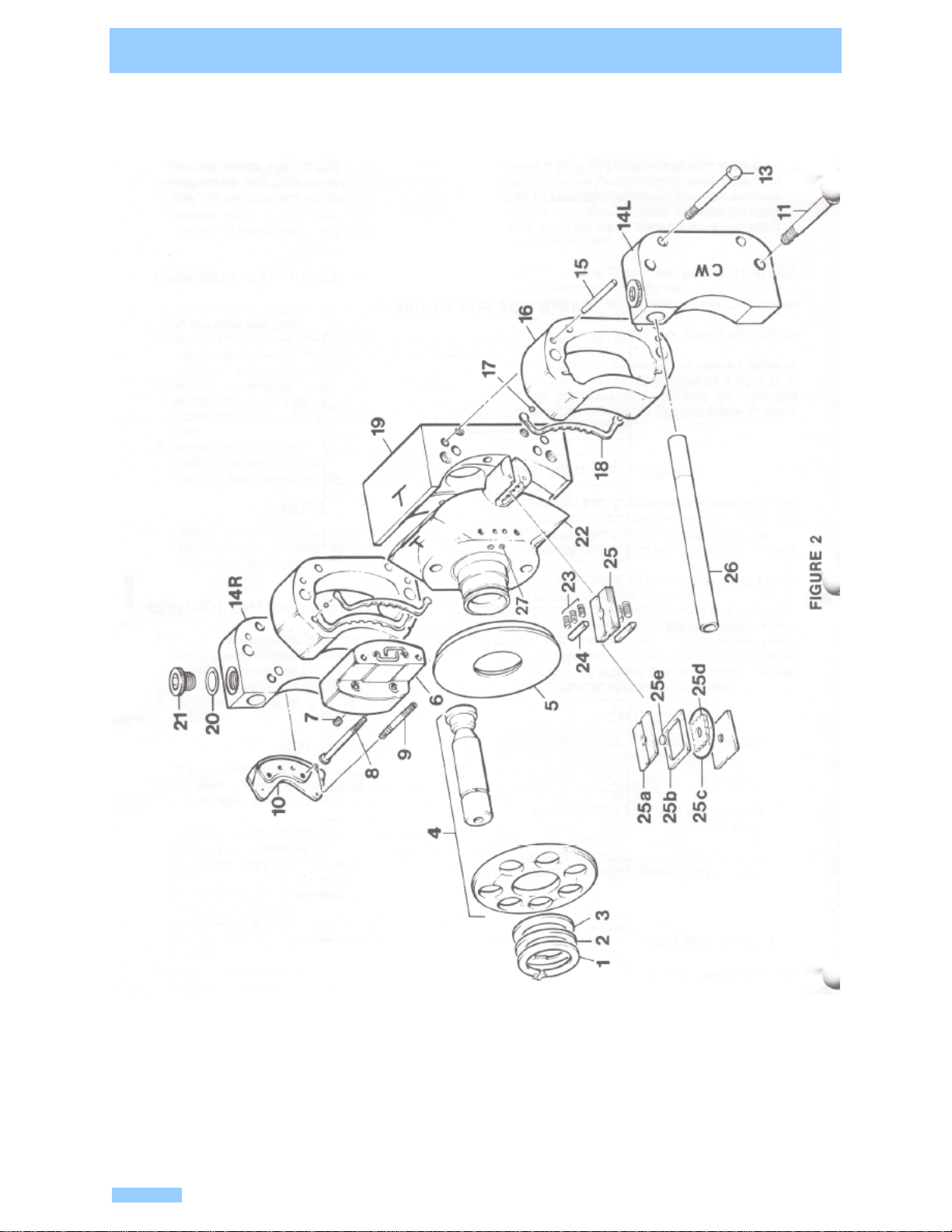
ROCKER CAM AND CONTROL STROKING ASSEMBLY (Figure 4)
1. Remove pressure feed tubes (5 and 6) from the cradle. DO NOT BEND THESE LINES.
2. Remove the assembly from the mounting flange and position on a clean surface with the override
tubes (2) in a horizontal position and located at the top.
3. Mark the cam (24) and cradle (20) as indicated in Figure 2. These marks will determine
positioning of parts during reassembly.
4. Position the assembly in an upright position on the flat surface of the cradle (see Figure 2).
5. Remove the retaining ring (1), thrust washer (2), flange bearing (3), piston and shoe assembly (4)
and creep plate (5) from the rocker cam (22).
6. Remove the two differential screws (9) from the rocker cam and remove the servo input parts (6,
7, 8 and 10).
CAUTION: Differential screws must be alternately removed one turn at a time.
7. Remove the four 1/2” screws (11) and four 3/8” screws (13) from the control chamber covers
(14R and 14L).
8. Remove the control chambers (16). Remove the seals (18), four steel balls (17) and dowel pins
(15).
9. Remove the vane seal cartridges (25), hold-down vanes (24) and springs (23) from the rocker
cam (22).
10. Remove the rocker cam from the cradle (19).
9
www.comoso.com
ASSEMBLY PROCEDURES
DRIVE SHAFT ASSEMBLY
Figure 1
1. Pass one retaining ring (3) over the internal end of drive shaft (1) and install in the groove near the
shaft seal surface. DO NOT PASS THE RING OVER THE SEAL SURFACE.
2. Slide the bearing (2) over the same end of the shaft and seat against the ring. Support only the
inner race of the bearing and press on the coupling end of the shaft. DO NOT USE EXCESSIVE
FORCE AND DISTORT OR DAMAGE THE RETAINING RING.
3. Install the other retaining ring (3) in the remaining ring groove. Be sure that both rings are fully
seated.
PARTS LIST FOR FIGURE 1
S13-43968 #1 Drive Shaft Assembly (Splined)
S13-43969 #2 Drive Shaft Assembly (W/Keyway)
Qty.Item #1 #2 Part
Number Description
11-- 033-71604 #1 (Splined) Drive Shaft
-- 1033-71601 #2 (W/7/16/KW) Drive Shaft
211230-82148 Shaft bearing MRC 110 KS
322033-71641 Retaining Ring
4-- 1033-71514 Square Key 7/15 x 1-1/2
10
www.comoso.com

ASSEMBLY PROCEDURES
ROCKER CAM ASSEMBLY (Figure 2
1. Position the rocker cradle (19) on a clean surface with the large flat side down.
2. Lightly oil curved surface of cradle. Position the rocker cam (22) on the cradle. Note the marks
made during disassembly indicating the top of the rocker cam and cradle.
VANE SEAL CARTRIDGES (Figure 2)
1. Install O-ring (25c) on spacer (25d) and insert in the vane seal (25b).
2. Install check valve (25e) inside of spacer and assemble between the backup plates (25a) with the
“V” notches exposed.
3. Install assembled vane seal cartridge in slotted boss on side of rocker cam as indicated. Repeat
steps 1, 2 and 3 on the other side of cam.
4. Install the four nylon holddown vanes (24) and twelve springs (23) in the slots on each side of the
vane seal cartridges (25).
NOTE: Install nylon holddown vanes with the beveled edge sloping away from the vane seal
cartridges.
CONTROL CHAMBERS (Figure 2)
1. Position both control chambers (16) on a clean surface with the seal grooves facing up.
2. Insert one steel ball (17) in each of the counter-bored holes at the end of the seal grooves.
3. Install seals (18) in grooves of the control chambers.
NOTE: The tapered side of the seals must be pushed into the grooves and the ends must cover
the steel balls.
4. Install the assembled control chambers (16) over the vane seal cartridges by rotating the chambers
until they slip over the vane seal cartridges, then rotate in the opposite direction until the 3/8” dowel
pin holes in the chambers align with the dowel pin holes in the rocker cradle (19). Install dowel pins
(15) through the control chambers and into the cradle.
5. Install chamber covers (14R) and (14L) on the control chambers (16). The covers must be installed
with the override tube (26) holes at the top. Note the marks made during disassembly to indicate the
top of rocker cam and cradle.
NOTE: Two sets of control chamber covers are available. The set marked CW must be installed in
the right hand rotation pump and the set marked CCW must be installed in the left hand rotation
pump. Rotation is determined from the shaft end of the unit.
6. Install two 1/2-13 hex head screws (11) in each side and torque to 75 ft.-lbs.
7. Install two 3/8-16 hex head screws, (13) in each side. Torque to 30 ft.-lbs.
8. Install O-ring (20) and hex socket plug (21) in each chamber cover.
9. Install override tubes (26) in reamed holes in each cover. These tubes must be a tight fit. If tubes
are loose, the ends may be expanded with a tapered punch. Tap the tubes in place with a plastic
mallet.
11
www.comoso.com

ASSEMBLY PROCEDURES
SERVO ASSEMBLY (Figure 2)
1. Install two #10-32 differential screws (9) in the servo plate (10) from the inside. Allow the screws to
extend 11/64” through the plate.
2. Install two orifice screws (7) in the servo stem (6).
3. Install servo stem on rocker cam using #10-32 screws (8). Torque to 70 in. lbs.
4. Install servo plate with the long end of the differential screws through the servo stem. Maintain light
finger pressure against the servo plate, alternately tighten screws 1/2 turn until plate is flush against
the servo stem. Torque the differential screws to 10 in.-lbs.
CAUTION: When tightened, screws must be .03-.10” below surface of servo plate.
NOTE: Install the servo stem and plate on the rocker cam input side. (9 o’clock position on “B”
suffix models, 3 o’clock position on “A” suffix models). Refer to control location column of series
model code.
PISTON AND SHOE ASSEMBLY (Figure 2)
1. Install creep plate (5) over center post of rocker cam (22).
2. Insert pistons and shoes into retainer and install entire assembly (4) against creep plate.
3. Install flange bearing (3) and thrust washer (2) over center post of cam and against shoe retainer.
4. Install the thickest retaining ring (1) that will fit in the groove on the rocker cam center post which will
allow a maximum clearance of .002-.004” between the creep plate and shoe faces. There are four
different retaining rings available for this tolerance. Each retaining ring is marked:.102/.101 thick,
blue dot; .104/.103 thick, red dot; .106/.105 thick, green dot; and .108/.107 thick, yellow dot. The
piston and shoe assembly must be free to move by hand. (5 ft./lbs. or less.)
12 www.comoso.com

ASSEMBLY PROCEDURES
PARTS LIST FOR FIGURE 2
No. Qty. Part No. Description
Retaining ring –use one only
033-71556 107 –108 thick w/yellow dot
033-71557 105-106 thick w/green dot
033-71558 103-104 thick w/red dot
11
033-71559 101-102 thick w/blue doe
21033-71565 Thrust washer
31033-71563 Bearing
S13-48761 Piston shoe & retainer assy. M11 only41S13-48760 Piston shoe & retainer assy. M14 only
51033-71569 Creep plate
61033-71596 Servo stem
72033-20641 Orifice screw
82359-09240 Socket head cap screw
92033-71651 Differential screw
10 1033-70548 Servo plate
11 4306-40189 Hex head screw 1/2-13 x 3
13 4306-40140 Hex head screw 3/8-16x2-3/4
**14R 1033-71598 Right side chamber cover C. W. rotation
**14L 1033-71597 Left side chamber cover C.W. rotation
15 4324-22428 Dowel pin
16 2033-71615 Control chamber
17 4201-06001 Steel ball
18 2606-25040 Control chamber seal
19 1033-71582 Rocker cradle
20 2691-00905 O-ring
21 2488-35020 Hex socket plug
22 1033-71580 Rocker cam
23 12 033-72233 Vane hold-down spring
24 4033-72234 Hold-down vane
25 2See below Vane seal cartridge
25a 4033-71608 Vane seal back-up plate
25b 2033-71611 Vane seal
25c 2691-00125 O-ring
25d 2033-71607 Vane spacer
25e 2033-70803 Check valve
26 2033-71609 Override tube
27 4447-00017 Lee plug
Items 6 through 24 can be ordered as a complete rocker cam & stroking assembly.
S13-43958 is for clockwise rotation motors with “B” suffix (input control on right side)
*Newer model motors don’t require screws #12
**Newer chamber covers are not drilled for use of screw #12.
13
www.comoso.com
ASSEMBLY PROCEDURES
14 www.comoso.com

ASSEMBLY PROCEDURES
BARREL AND HOLD-DOWN SHAFT ASSEMBLY (Figure 3)
1. Position the barrel (1) with the bores
facing down on a clean surface.
2. Install hold-down spring (3) into barrel
counter-bore.
3. Install spring retainer (5) into counter-bore
and seat against spring.
4. Install retaining ring (6) into barrel counter-
bore groove. Make sure retaining ring is
fully seated in groove.
5. Position barrel stop (4) over hold-down
shaft (2). Turn barrel on side and install
shaft and barrel stop through barrel
spline and hold-down spring.
PARTS LIST FOR FIGURE 3
Qty.No. M11 M14 Part
Number Description
1-- S13-45381 Barrel & sleeve assy. M11 only1-- 1S13-43965 Barrel & sleeve assy. M14 only
211033-71573 Hold-down shaft
311033-71562 Hold-down spring
411033-71561 Barrel stop
511033-71560 Spring retainer
611033-71564 Retaining ring
15
www.comoso.com

ASSEMBLY PROCEDURES
BARREL AND STROKING ASSEMBLY
TO MOUNTING FLANGE (Figure 4)
1. Install straight thread connectors (3) and O-rings
(4) into threaded holes in cradle.
2. Install right and left hand pressure feed tubes
(5 and 6) to connectors (3). Tighten connectors
until snug.
3. Position the mounting flange (9) with the large
open end facing up and install two dowel pins (8)
in the cradle mounting surface.
4. Install the rocker cam and cradle assembly (7)
over the dowel pins (8) in the mounting flange.
5. With cam and cradle installed, position mounting
flange on the side and install two 3/8-16 x 2 screws
through the seal retainer area into the cradle.
The screws are required to hold the rocker cam
assembly in place and will be removed later.
6. Return the mounting flange to an upright position
and tilt the rocker cam to either extreme attitude
in the cradle.
7. Position the barrel and shaft assembly (1)
directly over the pistons. Starting with the upper-
most piston, guide them one at a time into the
barrel bores. Return the cam to a level position
in the cradle.
PARTS LIST FOR FIGURE 4
No. Qty. Part No. Description
11See Fig. 3 Barrel & hold-down shaft assy.
22033-71609 Override pressure tubes
32492-15265 Connector
42691-00902 O-ring
51S13-43967 Tubing assy. (right side)
61S13-43966 Tubing assy. (left side)
71See Fig. 2 Rocker cam & stroking assy.
82324-23216 Dowel pin
91033-71546 Mounting flange
10 4033-72664 Locating sleeve
16
www.comoso.com

ASSEMBLY PROCEDURES
S13-43962
HOUSING ASSEMBLY (Figure 5)
1. Position housing (1) on a flat surface with the large open end up.
2. Press the bearing (2) into the housing bore until seated. DO NOT HAMMER OR BEAT BEARING
INTO PLACE.
3. Position housing on side and install roll pin (3) through hole in control cover pad. Roll pin must be
installed 3/8” below pad surface. Install two dowel pins (4) in the blind holes in the same pad.
4. Repeat step 3 on the opposite side of the housing.
5. Install O-ring (5) and plug (6) in the bottom of housing. Roll pins (3) are in the bottom half of the
housing.
PARTS LIST FOR FIGURE 5
Housing Assembly S13-43962
No. Qty. Part No. Description
11033-71578 Housing
21033-71516 Bearing
32325-16320 Roll pin
44324-21608 Dowel pin
52691-00912 O-ring
62488-35014 Plug
17 www.comoso.com
ASSEMBLY PROCEDURES
HOUSING ASSEMBLY INSTALLATION (Figure 6)
1. Install face plate pins (1) in the holes provided in
the barrel face.
2. Apply heavy grease to the surface of the barrel and
install the face plate (2) over the face plate
pins.
CAUTION: The face plate must be fully seated on the
barrel face and pins with the steel side towards the
barrel.
3. Install gasket (3) over the 4 locating sleeves in the
mounting flange.
4. Install the housing assembly (4) over the barrel and
auxiliary shaft assembly. Carefully guide the over-
ride tubes and pressure feed tubes (items 2,5 and 6,
Figure 4) through the housing assembly. Position
the pressure feed tubes in the slots in the housing
face.
PARTS LIST FOR FIGURE 6
No. Qty. Part No. Description
12033-49825 Face plate pins
1033-71921 Barrel face plate M11 only2
1033-71575 Barrel face plate M14 only
31033-71602 Housing gasket
41S13-43962 Housing assembly
18 www.comoso.com

ASSEMBLY PROCEDURES
PORT BLOCK INSTALLATION (Figure 7)
1. Position the motor with the unplugged hole in the housing assembly (6) facing up. Install gasket (5)
on the housing.
2. Install two dowel pins (3) in the face of the port block assembly (2).
3. Apply heavy grease to the rear of the port plate (4) and install over the dowel pins. Port plate must
be fully seated on the pins.
4. Install the port block assembly over the hold-down shaft. Make sure that tubes (2, 5 and 6, Figure 4)
are fully seated and port plate remains firmly secured on the pins.
5.Install the four bolts (1). Do not drop the bolts in place as the threads may be damaged. Torque
bolts evenly in 50 lb. increments to 350 ft.-lbs.
BARREL HOLD-DOWN (Figure 8)
1. Position the motor in the horizontal position.
2. Install seal ring (6) on hold-down shaft. Place bearing (7) between the two thrust washers (8) and
install around the seal ring.
3. Install hold-down nut (4) on auxiliary shaft and tighten until snug (10 ft.-lbs. maximum). Back hold-
down nut off until second slot in nut is aligned with the cotter pin hole in shaft.
4. Install cotter pin (5) through hold-down nut and auxiliary shaft. Bend one tang over end of shaft.
NOTE: DO NOT RE-USE COTTER PIN. DO NOT BEND TANG OVER MORE THAN ONCE.
5. Install O-ring (2) on end cover. Lubricate O-ring and install cover over hold-down nut.
6. Depress end cover and install retaining ring (1)
PARTS LIST FOR FIGURE 7
No. Qty. Part No. Description
14306-40112 Hex head cap screw
21033-71521 Port block
32324-21610 Dowel pin
1033-71916 Port plate M11 only41033-71551 Port plate M14 only
51033-71579 Port block gasket
61488-35041 Plug
71691-00906 O-ring
84488-35001 Plug
94691-00904 O-ring
PARTS LIST FOR FIGURE 8
No. Qty. Part No. Description
11356-65095 Retaining ring
21671-00138 O-ring
31033-70537 End cover
41033-72026 Hold-down nut
51322-03324 Cotter pin
61033-72101 Seat ring
71230-82164 Thrust bearing
82350-10081 Thrust washer
19
www.comoso.com

ASSEMBLY PROCEDURES
20 www.comoso.com
This manual suits for next models
1
Table of contents
Other Denison Hydraulics Engine manuals


Popular Engine manuals by other brands


BONFIGLIOLI
BONFIGLIOLI AS Series manual

Kohler
Kohler K91 Service manual

Bayliner
Bayliner MCM 7.4L Service manual

Briggs & Stratton
Briggs & Stratton 11A600 Operating & maintenance instructions

Performance
Performance ZZ454 Specifications

Idex
Idex MICROPUMP EagleDrive MS Installation, operation and warranty information