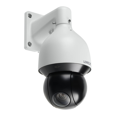
Dennard 2055 User manual

ISSUE 2
SOFTWARE
V
.4…2226

Index
1.0 The Dennard 2055 Dome
Outline Specification
1.1 Programmable Features
1.1.1 Positions
1.1.2 Position Titles
1.1.3 Sequences
1.1.4 Queues
1.1.5 Alarm Response
1.1.6 Sectors
1.1.7 Bottom Flip
1.1.8 Camera Mode
1.1.9 Digital Zoom Extension
1.1.10 Dome Selection Cursor
1.1.11 Text Positioning and Selection
1.1.12 Joystick Range
1.1.13 Host polling
1.1.14 Error Reporting
1.1.15 Activity light
1.1.16 Default Action
1.1.17 Set video amplification
1.1.18 Privacy mode
2.0 Unit Health Monitoring
2.1 Error Reporting
2.2 Testing and remedial measures
2.2.1 Testing Pan and Tilt Drives
2.2.2 Pan and Tilt Axes Excursions
2.3 Factory Defaults
3.0 Operation with a Control Panel
4.0 Operation through Dome internal Menu Structure
4.1 Operator Menu
4.2 Supervisor Menu
4.3 Technician Menu
5.0 Menu Flow Chart
APPENDIX.1. Type 2055 Access from various controllers
APPENDIX.2. Trouble shooting guide
2055 Menu System Manual Sheet.1

1.0 THE DENNARD TYPE 2055 DOME CAMERA
The Dennard 2055 Dome Camera is a precision unit, offering a wide variable speed
range, together with a large pre-set memory for positions, sequences (tours) and alarm
response. It has a switchable colour/monochrome camera (colour only on indoor units)
with an 18:1 zoom lens plus x 4 digital enhancement.
The unit has a comprehensive set of features as standard, which can be tailored for
individual preferences. These can be easily accessed through an internally generated
set of menus overlaid on the video signal if the controller does not have a suitable
layout. Each Dome Camera is delivered with a separate weatherproof power supply.
Outline Specification:
Speed range 0.05 to 300 º / second max (both Pan and Tilt)
Repeatability 5 minutes of arc
Optical range 4.1mm to 73.8mm zoom;
F1.4toF3.0
Auto-focus with manual override
Video sensitivity 3 lux colour
0.2 lux monochrome
Video resolution 768 horizontal x 494 vertical, pixels
More than 470 TVL
Video output 1.0v p-p composite, negative synch
Control RS 485 half duplex or simplex, 9600 Baud OR
'up the co-ax' using built in DEN PANEL or BAX PANEL
protocol converter for Dennard, BBV & DM or Baxall controls
Storage capacity 250 positions, with identifying title of up to 20 characters
100 sequences of up to 20 positions
50 queues of up to 20 sequences
250 deep alarm response memory
32 Sectors
Power Supply 24Va.c, Camera & control electronics:-10VA
Heater & blower unit:-10VA
Dimensions Dome Camera:150mm Diameter hemisphere x 230mm overall
Power Supply: 165L x 135W x 95H.
Protection BS EN 60529 to level IP66 (no water ingress)
Weight Dome Camera: 1.7 kg + mounting bracket
Power Supply: 1.3 kg
Mounting Configurations Ceiling mount, pendant mount, wall bracket, corner mount,
snowdrop & tile mounts available
2055 Menu System Manual Sheet.2

1.1 Programmable Features
The Dennard 2055 Dome Camera has a number of features which can be selected by
the system supervisor when the dome is installed. Any of these can be altered
subsequently, at any time, or cancelled altogether as relevant, to give the best
operational responses for any particular application.
These are all invoked or cancelled through on-screen menu structures, described in
section 4, and the settings are then retained in non-volatile memory so that they are not
affected by a loss of power.
The features and what they offer are described below:
1.1.1 Positions
Up to 250 positions can be stored and recalled at any time. Each position stores the
Pan, Tilt, Zoom, and Focus positions as well as the position title.
1.1.2 Position Titles
Each position title can have up to 20 alphanumeric characters to identify the associated
position uniquely. The default title position lies at the bottom left hand corner of the
video picture, left justified.
These Position Titles only appear at the position they identify: any movement from that
position will remove them.
1.1.3 Sequences
Up to 100 Sequences can be stored and recalled at any time. Each sequence can
contain up to 20 positions together with a ‘dwell’ time at each position (2 - 18 seconds in
increments of 2 seconds: longer delays are set by repeating a position) plus the length
of time (2 - 18 seconds again in 2 second increments) that the dome unit must take to
reach the next position, when the time comes to leave the current position. When the
last position in the sequence is reached, the sequence ‘loops’ back to the first position,
taking the time set in the last position/dwell/time-forward block.
1.1.4 Queues
Up to 50 queues can be stored. The purpose of a queue is to form long sequences
without difficulty in documenting a long ‘thread’ of positions, by effectively forming a
sequence of sequences. Each queue links up to 20 sequences together in the same
way that sequences link positions, except that each entry in the queue contains only a
sequence number and a time which links from the last position in one sequence to the
first position in the next; this time (in queue operation only) replaces the time held in the
last position block in the sequence.
1.1.5 Alarm Response
Up to 250 Alarm responses can be stored. Each alarm response stores a specified
position, sequence, or queue against an alarm number. This is a very powerful feature,
allowing an unlimited number of domes, or any other device conforming to the Dennard
protocol to invoke a pre-set alarm action from one single loop broadcast command.
.
2055 Menu System Manual Sheet.3

1.1.6 Sectors
There are 32 equal length sectors which may be programmed with an identifying title of
up to 20 alphanumeric characters to identify the general direction the dome is pointing:
these all correspond to Pan direction and are unaffected by Tilt position.
They appear in the same location as Position Titles and replace them when the dome is
resting at a pre-set position.
1.1.7 Bottom Flip
The dome will automatically pan through 180 degrees as fast as possible when tilted
fully down so that it is possible to follow (a person) moving immediately underneath the
dome with only a single joystick direction to consider.
1.1.8 Camera Mode
The camera can be switched between colour and monochrome mode, or can be
selected as colour/mono in which case it will automatically switch to mono when the
light level is insufficient for good quality colour pictures.
1.1.9 Digital Zoom Extension
The camera system also allows an extension of the optical zoom by selecting more of
the central part of the picture and expanding this to fill the frame. This feature is
selectable.
1.1.10 Dome Selection Cursor
The menu structure itself, and the choices and selections offered, are searched and
invoked by a single cursor or flashing character and the direction in which this moves
depends on the particular control panel in use. In case the joystick or operating keys
move the cursor ‘the wrong way’ its direction of movement can be reversed, separately
for horizontal and vertical movement.
1.1.11 Text Positioning and Selection
All text can be positioned where it is wanted, replaced with default text (eg: Position 31,
or Sector 18), or removed as required.
1.1.12 Joystick Range
Even if the control panel has a wide range proportional joystick output, the Dennard
Dome has such a wide speed range that both a fast and a slow speed range are
needed to realise the full performance (provided of course that the control panel in
question has a facility to invoke these separately).
The slow speed range is simply the same as the fast speed range following the same
in-built correlation law, but divided by a constant. This constant can be set between 2
and 128.
When this facility is used and a change of range is requested, the change itself will not
occur until the joystick is momentarily returned to zero.
2055 Menu System Manual Sheet.4

1.1.13 Host polling
The Dennard protocol allows either half-duplex (ON) or simplex operation (OFF). The
dome is delivered set for 'simplex' operation..
1.1.14 Error Reporting
The Dennard Dome constantly monitors its own health, and should any difficulties occur
(for instance, with dome protocol responses enabled it will be able to signal that there is
an intermittent serial control problem, which would otherwise be undetectable) is able to
indicate what may be wrong by a flashing square in the top right hand corner of the
transmitted picture; the cause can subsequently be requested when convenient. This
reporting can be disabled from the Technicians menu.
1.1.15 Activity light
A green led provides some diagnostic help when first switching the dome on and also
indicates when command signals are received. As it may be visible externally it can be
switched on or off.
1.1.16 User Timeout
There is a possibility that the dome may be left pointing at an unhelpful scene and for
whatever reason ‘forgotten’. To cater for this eventuality, three pre-sets have the
specific function of acting to prevent this happening. These are Position 001, Sequence
001, and Queue 01.
A delay of between 1 and 999 seconds may be set, and if this time is exceeded after
any joystick/key entry Pan and Tilt input at the Control Panel then the default action will
occur. Once set the delay time is displayed
If a delay time of 0 is set, no default action will occur.
If a Dome menu is left waiting for an input for more than 3 minutes then the system
times out and the dome resumes its previous activity.
1.1.17 Set video amplification
This facility allows the video gain to be increased from the normal setting in three steps
to a maximum setting. Video lift can be tuned on or off, it is normally set to the off
position. A double arrow to the right of the menu indicates the current selection.
1.1.18 Privacy mode
It is sometimes desirable to prevent operators from viewing certain areas. To meet this
requirement the Privacy mode allows black patches to be set up to cover these areas.
The size of the patch is the size of the monitor view at whatever zoom setting is used.
When zooming out the patch reduces in size so that it only covers the original area.
2055 Menu System Manual Sheet.5

2.0 Unit Health Monitoring
The unit health can be checked by taking account of any error messages which may
occur, and through the supervisor menu.
2.1 Error Reporting
If an error should occur, an error description will be written at the bottom of the screen.
If error reporting is disabled through the Technicians Menu-Enable/Disable options-
Enable Error Display, then errors are indicated by a flashing square in the top right hand
corner of the screen.
2.2 Testing and remedial measures
Access through the Technicians menu.
2.2.1 Testing Pan and Tilt Drives
Access through the Technicians menu
2.3 Factory Defaults
Access through the Technicians menu (If invoked all programmed settings will be lost)
3.0 Operation with a Control Panel
This will vary between control panels: refer to the Controller Manual.
4.0 Operation through a Dome Menu Structure using Dennard controllers
The 2055 Dome Camera is an open protocol device; consequently there will be several
different manufacturers controllers available to drive it. All of the many features offered by
the dome are programmed from one of three menu structures. Each controller will have
individual control configurations which makes it essential that the user reads the
controller manual to ascertain which button activation gives access to the menu features.
Appendix 1 gives these functions for several popular controllers.
These instructions will guide you through the menu structure when using the 2055 &
PSU
(with address set to No. 253… DEN PANEL)
controlled by either a
dtx400dc
or a
dtx1000dc
The Menus appear on the screen when activated by the following commands:
When using dtx1000dc When using dtx400dc
User Menu shift wash shift
1
Supervisor Menu (password required) shift wipe shift 2
Technicians Menu (password required) shift autopan shift 3
On activation, the menu will appear on the monitor screen against the normal video scene
background a “cursor” on the left hand edge. A choice is made by positioning the cursor
over the desired feature and when it flashes operating an “ACCEPT” button(s) which for
the Dennard controllers are as follows:-
dtx1000dc is, hold preset
button and tap CAMERA SELECT 1
dtx 400dc is, press preset 1 button
2055 Menu System Manual Sheet.6

4.1 User Menu
The USER MENU is straightforward, with all the choices offered on just two screens.
When called, the screen will display the following options, against a camera display
background, with a cursor at the left hand edge:
Go to Position
Start Sequence
Start Queue
Technicians Menu
Supervisors Menu
Exit
This menu allows the operator to recall the full range of stored Positions, Sequences,
and Queues even if the control panel has neither the numerical range nor general ability
to do so, but the menu does not allow any initial programming.
The required choice is made by positioning the cursor using the joystick or pan & tilt
direction buttons, then pressing the ACCEPT button(s) on the control panel; if Exit is
chosen the menu is cleared and no other action is taken by the dome.
The display will otherwise prompt for the required numerical entry with the following
subsidiary menu:
Position Number _ _ _ (or Sequence, or Queue)
0 1 2 3 4 5 6 7 8 9
Accept Entry
Clear Entry
Cancel
The cursor is run across the numerical line, using the joystick or control buttons, until
the desired number is reached. The characters will flash their position in turn and as
soon as one is selected with the ACCEPT button(s) it will be displayed in the _ _ _ part
of the display.
Leading zeros need not be entered (eg 001 may be entered 1), but the entry must be
within range, eg 001 - 250 for Positions, 001 - 100 for Sequences, and 01 - 50 for
Queues. Entries outside the range will cause an ‘Illegal Entry; message to flash, and the
entry must be cleared and re-entered.
When all three digits have been selected, Accept Entry will invoke that choice and the
screen will automatically clear to the camera signal.
To change the choice ‘Clear Entry’ will start the process again
2055 Menu System Manual Sheet.7

When the Technician or Supervisor menu is called the following screen appears. The
password or Pin Number is keyed in using the same method as used with previous
entries.
Enter PIN _ _ _ _
0 1 2 3 4 5 6 7 8 9
Accept Entry
Clear Entry
Cancel
The cursor is run across the numerical line, using the joystick or control buttons, until
the desired number is reached. The characters will flash their position in turn and as
soon as one is selected with the ACCEPT button(s) it will be displayed in the _ _ _ _
part of the display.
When all four digits have been selected, Accept Entry will invoke that choice and the
screen will automatically change to the selected menu i.e. the Technician or Supervisor
menu.
THE FACTORY SET PASSWORD, (WHICH CAN BE CHANGED BY THE TECHNICIAN
OR SUPERVISOR) IS PRINTED ON A LOOSE LEAF PAGE OF THIS MANUAL.TO
PREVENT UNAUTHORISED CHANGES BEING MADE TO SETTINGS OR SET-UPS IT
IS ADVISED THAT PASSWORDS ARE KEPT IN A SAFE PLACE.
2055 Menu System Manual Sheet.8

4.2 Supervisor Menu
The SUPERVISOR MENU allows the supervisor not only to duplicate the operator
menu functions, but also to programme Positions (with their identifying title),
Sequences, and Queues. Additionally, cursor setting and text positioning and selection
are accessed here.
The functions are split into a series of underlying menus in ‘layers’. When exiting from
any underlying menu, the overlying menu is re-selected: the functions which are less
likely to be needed lie deeper in the structure.
The Supervisor Menu displays:
Pos/Seq/Queue/Alarm
Options
Change Password
Privacy
Exit
The first Supervisor Menu option calls up the following underlying Preset Menu, which
offers straightforward access to position, sequence, queue and alarm pre-sets:
Store Position
Store Sequence
Store Queue
Store Alarm
Go to Position
Start Sequence
Start Queue
Default PSQ
Exit
Choice is identical to that for the Operator menu for pre-set recall.
Store Position. Programming a Position requires the camera to be positioned and the
zoom angle selected first and then, when the menu has been invoked, the ‘Store
Position’ option selected. The display will revert to one almost identical to the one used
for recalling a Position.
Position Number _ _ _
0 1 2 3 4 5 6 7 8 9
Accept Entry
Clear Entry
Exit
Erase from NVM
2055 Menu System Manual Sheet.9

When the Position number (between 001 and 250) is accepted a new display will allow
the Position Title to be stored, as follows:
A B C D E F G H I J K L M :
N O P Q R S T U V W X Y Z /
a b c d e f g h I j k l m -
n o p q r s t u v w x y z ,
0 1 2 3 4 5 6 7 8 9 * = +
Backspace
Set Insert Mode
Cancel edit
Accept edit
_ _ _ _ _ _ _ _ _ _ _ _
The title choice is made as usual with the cursor and accepted when ready (which will
store the chosen Title with the stored Position), cleared for a different choice, or exited
(which will store the Position without an associated title). The title appears in the _ _
space as it is compiled, although the _’s are shown here only to indicate where this
happens - they do not appear in reality on the screen.
.
Store Sequence. Choosing to program a Sequence first requires the Sequence
Number to be entered in an identical procedure to selecting a Position (except that the
range must lie between 001 and 100). Once the number has been accepted, a
subsidiary menu is displayed:
Item _ _ _ in sequence _ _ _
P P P D S
Old _ _ _ _ _
New _ _ _ _ _
0 1 2 3 4 5 6 7 8 9
Accept Entry
Clear Entry
Cancel Sequence Edit
Store Sequence
Here the entry format follows the now-familiar procedure but the _ _ _ characters have
specific functions. The first three characters PPP represent a Position. The fourth
character Dis the dwell time that the camera must spend stationary at that position, in
two second increments (so 4 indicates a dwell of 8 seconds). The fifth and final
character Srepresents the time, again in two second increments, that the camera must
take to reach the next position in the sequence.
When all five characters are completed and then accepted, the display clears the entry
ready to receive the next ‘data block’, until all entries are complete and the Sequence is
itself stored.
2055 Menu System Manual Sheet.10

Store Queue. Storing a queue is an identical procedure to storing a sequence, except
that the range is 01 – 50 and the data blocks in the subsidiary menu SSS, represent the
Sequence number. Enter the first Sequence number of your Queue and Accept Entry
then continue with all of the other Sequence numbers and finally Store Queue.
Store Alarm. Alarm storage allows a specified position P, sequence S, or queue Q(To
select, use the codes : 001 = Q, 010 = S, 100 = P) to be stored with their identification
number nnn which can be invoked by an alarm procedure with a single broadcast
command. The alarm action will be sustained for a duration set by the use timeout.
Default PSQ enables the Supervisor to set the default order after a user timeout
between position P, sequence Sor queue Q. The priority is factory set as P= Priority
1, S= Priority 2, Q= Priority 3.
If you want to change the priority so that S is priority 1, P is priority 2 and Q is priority 3
then in the New_ _ _ line of the menu place a 1 under S, 2 under P and a 3 under Q.
The second choice from the Supervisor Menu calls the underlying Options menu,
which has underlying menus of its own; this displays:
Position Text
Sector text
Set user timeout
Enable digital zoom
Disable digital zoom Enable freeze frame
Enable bottom flip Disable freeze frame
Disable bottom flip Exit
More
The first choice selects the Position Text Menu (which has a further underlying menu
of its own), which displays:
Left justify position text
Right just. position text
Enable dflt position text
Disable dflt position text
Edit dflt position text
Exit
The first two options decide where the position text is displayed, and the next two allow
the default position display, ‘pNNN’. The fifth option has an underlying menu that allows
the position text to be changed thus:
A B C D E F G H I J K L M :
N O P Q R S T U V W X Y Z /
a b c d e f g h I j k l m -
n o p q r s t u v w x y z ,
0 1 2 3 4 5 6 7 8 9 * = +
Backspace
Set Insert Mode
Cancel edit
Accept edit
2055 Menu System Manual Sheet.11

The second choice from the Options menu calls the Sector Text option, which
displays:
Enable sector text
Disable sector text
Enable dflt sector text
Disable dflt sector text
Edit dflt sector text
Edit sector text
Exit
The third choice from the Options menu is the Set user timeout which sets the
default timeout from 1 - 999 seconds. This is the time between the last joystick (or P/T
keys) input from the operator, and an automatic move to the start of the default Queue,
Sequence, or to the default Position, provided these have in fact been programmed.
Setting a time of 0 second switches the default mechanism off altogether.
The fourth and fifth choices from the Options menu enable or disable the digital zoom
on the camera. If this is enabled this feature is automatically invoked by the camera
when the zoom control is held in after the optical zoom has reached its mechanical end
stop.
The digital zoom setting is stored in pre-set positions, but if the digital zoom option is
disabled, the pre-set positions involved will only return the position with the optical zoom
at full extension.
The option selected will be briefly confirmed at the bottom of the screen.
The sixth and seventh options turn the bottom flip feature on or off.
More gives access to the freeze frame enable /disable option, this option when selected
will hold the last view on the display while the dome moves at full speed to a preset
position on arrival the normal image view is displayed. This avoids a blur as the dome
moves at high speed to preset positions.
The third option on the Supervisor Menu is Change Password which is carried out
on the following screen display .
Enter PIN _ _ _ _
0 1 2 3 4 5 6 7 8 9
Accept Entry
Clear Entry
Cancel
Key in your new PIN (password) and accept the entry.
Make a note of the new PIN number and keep it in a safe place
2055 Menu System Manual Sheet.12

The final option on the Supervisor Menu is Privacy. Accepting this option will display
the following screen menu.
Define new privacy patch
Clear all privacy patches
Exit
Selection of Define new privacy patch will enable you to "black out" the view displayed
on the monitor.
To set up a privacy patch use the following procedure.
Ensure the dome is not in programme mode, ie: you have full manual control.
Pan & tilt the dome and zoom in to the area that requires a privacy blanket.
Go into the dome programme mode, ( Appendix 1 of this manual gives access procedures
for various popular controllers) accept Supervisors Menu, enter the PIN number, accept
Privacy, which will then display the privacy window:
Define new privacy patch
Clear all privacy patches
Exit
Accepting Define new privacy patch will black out the displayed image, but as you zoom
out the black screen will reduce to a patch which will reduce in size (in steps) as you zoom
further out. The software will support 6 such patches per screen. Accepting Define new
privacy patch will also take you out of the dome menus. To add another privacy patch
you will have to enter the Supervisor Menu again and repeat the whole of the above
procedure.
Clear all privacy patches when invoked will remove ALL previously stored privacy
patches.
2055 Menu System Manual Sheet.13

4.3 Technician Menu
The TECHNICIAN MENU has one level of underlying menus, and determines overall
operating dome features. This menu will be little used after the dome is first installed
and commissioned.
When called, it displays:
Camera set up
Enable/Disable options
Host comms options
Joystick divide
Joystick controls reverse
Miscellaneous Services
Change Password
Exit
The first Technician Menu choice is the Camera set up menu which displays:
Colour only
Mono only
Colour/Mono
Position manual focus
Position Auto focus
Auto frame integration
Normal frame integration Enable near focus
More Disable near focus
Exit Exit
Most of these options are self explanatory. When Colour/Mono is enabled the camera will
operate in colour mode until the light level falls below a predetermined value when it will
automatically switch to mono mode. The reverse will occur when the light returns to a
suitable level for colour operation.
Enable near focus allows the camera to focus at objects less than a metre away ,for
viewing close objects but should be disabled outdoors, which is the default position,
otherwise it will auto focus onto raindrops that fall on the hemisphere.
The second Technician Menu choice is Enable/Disable options, which displays:
Local Text Edit
Remote Text Edit
Enable Error Display
Disable Error Display
Enable head info Display
Disable head info Display
Left justify head info
Right justify head info
Exit
2055 Menu System Manual Sheet.14

The first two options determine whether screen text will be edited locally, that is
selected from the dome’s own screen options; or whether it is compiled at the system
Control Panel and transferred to the dome within the Dennard serial protocol.
The third and fourth options enable or disable the flashing error square that appears in
the top right hand corner of the screen, indicating some form of error in the system.
The fifth and sixth options enable or disable on screen camera identification at the
bottom of the display and options seven and eight enable the ident text to be positioned
on the left or right.
The Technician Menu third option selects the Host comms option menu and is
displayed as follows:
Enable Activity LED
Disable Activity LED
Host polling ON
Host polling OFF
Exit
The first and second options turn the small green LED in the dome on or off.
The third and fourth options determine whether the dome responds to messages in half
duplex serial communications, or acts in simplex mode without answering.
The Technician Menu fourth option selects the underlying Joystick divide (or speed
Menu), which determines the relationship between the fast and slow joystick speeds
where the control panel is able to offer this feature. This menu displays:
Divide by 2
Divide by 4
Divide by 8
Divide by 16
Divide by 32
Divide by 64
Divide by 128
Exit
The selection mode simply determines the mathematical ratio between fast and slow
speeds for Pan & Tilt and once made is briefly confirmed at the bottom of the screen.
2055 Menu System Manual Sheet.15

The Technician Menu fifth option Joystick control reverse enables the factory set
joystick directions for controlling the camera or the cursor to be reversed. The menu
display is:
Default pan direction
Reverse pan direction
Default tilt direction
Reverse tilt direction
Default horizontal cursor
Reverse horizontal cursor
Default vertical cursor
Reverse vertical cursor
Exit
The Technician Menu option six Miscellaneous Services displays as follows:
Software version
Homing values
Load factory defaults
Home servos
Reset Head
Set video amplification
Exit
The first choice confirms the software issue status.
The second choice gives the numerical value of the Pan and Tilt ranges, which will
show potential problems if the ranges are not what they should be.
The third choice loads all the factory settings: this will cancel anything that has been
stored or set, and clearly should not be used lightly!
The fourth choice starts the power up homing servos procedure which exercises all the
dome camera movement functions.
The fifth choice resets the pan & tilt and is in affect a reboot of the system.
2055 Menu System Manual Sheet.16

The final choice Set video amplification enables boost and lift for the video to
compensate for different types/lengths of coax. Selection introduces a further menu ie:
Video gain 1 / normal
Video gain 2
Video gain 3
Video gain 4 / max
Video lift off
Video lift on
Exit
Video gain is factory set at 1 with Video lift off, different settings are made in the usual
way. A double arrow to the right of the command indicates the current choice.
The Technician Menu seventh option allows the password to be changed and is the
same procedure as used on the Supervisor Menu password change ie:
Enter PIN _ _ _ _
0 1 2 3 4 5 6 7 8 9
Accept Entry
Clear Entry
Cancel
5.0 Menu Flow Chart
The three sheets can be removed and joined to produce a full flow diagram of the menu
system.
APPENDIX.1. 2055 programme access from various controllers
APPENDIX.2. Trouble shooting guide
2055 Menu System Manual Sheet.17

APPENDIX.1.
BAXALL / VISTA controllers
UP THE COAX CONTROL
The controller telemetry must be configured as follows:-
1: Rx attached, needs to be set to DC
2:Telemetry mode, needs to be set to STANDARD
The 2055 Dome address switches need to be set to BAX DC PANEL
See page 10 of the Dennard 2055 product guide, supplied with each Dome.
(Blue rotary address switch set to F…. Yellow rotary address switch set to E)
STORING PRESET POSITIONS:
(It is quicker using the Baxall controller software rather than using the 2055 Dome
software )
To programme a preset via the controller, enable the TELEMETRY, CAMERA and WIPE
keys.
Move the camera to the desired position.
Press the function key and enter the preset number using the number keys, then press
the preset key.
At this stage the preset menu from the dome will be displayed on the screen enabling you
to key in a preset identification. Text can be entered by moving the cursor under each
letter/number in turn using the joystick then pressing the WASH key to accept.
When you have finished entering text close the menu by moving the cursor down to the
Accept edit line and accept by pressing the WASH key.
If you don't want to add a preset identification move the cursor down to the Accept edit
line and accept by pressing the WASH key.
Once the presets have been stored switch off the CAMERA and WIPE functions for
normal operation.
2055 PROGRAMMING:
Access to the dome menu can be achieved by enabling the TELEMETRY, CAMERA and
WIPE buttons then pressing & holding the preset key, pressing & holding key 6 then
release the preset key then key 6. This will give you access to the operator menu. The
Supervisor menu (pin number 1111) and Technicians menu (pin number 9999) can
be accessed from this menu. The WASH button is used to enter/accept
2055 Menu System Manual Appendix 1 Sheet.A1-1

Dedicated Micros Digital Sprite 2
UP THE COAX CONTROL
The controller telemetry must be configured as follows:-
BBV Telemetry control in the Dedicated Micros Alarm and Preset Menu
The 2055 Dome address switches need to be set to DEN PANEL
See page 10 of the Dennard 2055 product guide, supplied with each Dome.
(Blue rotary address switch set to F…. Yellow rotary address switch set to D)
STORING PRESET POSITIONS:
(It is quicker using the Sprite 2 controller software rather than using the 2055 Dome
software)
Move camera to desired position.
Press and hold the preset key until save preset enter preset number appears on the
screen.
Enter the preset number using the number keys but the number must be proceeded with a
10 for presets N°1 to 9
e.g. For preset N°1 enter 10 then 1, for N°2 enter 10 then 2 and so on up to N°9. From
N°10 up to N°99 use the 10 key to replace 0.
At this stage the preset menu from the dome will be displayed on the screen enabling you
to key in a preset identification. Text can be entered by moving the cursor under each
letter/number in turn using the joystick then pressing the preset,1, enter keys to accept.
When you have finished entering text close the menu by moving the cursor down to the
Accept edit line and accept by pressing the preset,1, enter keys.
If you don't want to add a preset identification move the cursor down to the Accept edit
line and accept by pressing the preset,1, enter keys.
On the Digital Sprite there are two enter/accept commands.
(1) Press the preset key unit go to position is shown on the screen then press
key 1then the enter key i.e. preset,1, enter
(2)Press the preset key until go to position is shown on the screen then key 10
followed by key 1. i.e. preset,10,1
TYPE 2055 PROGRAMMING:
To access the 2050 dome menus, the following key presses are used.
For the Operator menu press: ∗
∗∗
∗8 8 9 10 10 2
For the Supervisor menu press: ∗
∗∗
∗8 8 9 10 10 3 (Pin number 1111)
For the Technician menu press: ∗
∗∗
∗8 8 9 10 10 4 (Pin number 9999)
2055 Menu System Manual Appendix 1 Sheet.A1-2
Table of contents
Other Dennard Security Camera manuals
