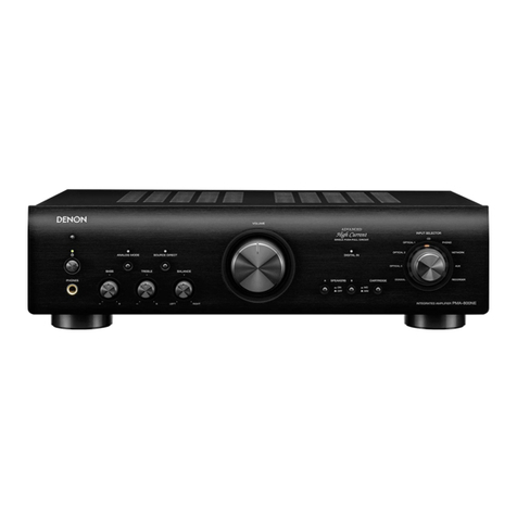
Denon PMA-1520AE User manual

Appendix
TipsSettingsPlaybackConnections
Contents
Front panel Rear panel IndexRemote
PMA-1520AE
INTEGRATED AMPLIFIER
Owner’s Manual
You can print more than one page of a PDF onto a single sheet of paper.

2
Appendix
TipsSettingsPlaybackConnections
Front panel Rear panel IndexRemote
Contents
Accessories························································································ 3
Inserting the batteries ······································································ 4
Operating range of the remote control unit ····································· 4
Features······························································································ 5
Part names and functions
Front panel ························································································ 6
Rear panel·························································································· 9
Remote control unit······································································ 10
Amplifier operation········································································· 10
CD player operation········································································ 11
Network audio player operation ····················································· 12
Connections
Speaker connection ······································································ 14
Connecting the speakers cables ···················································· 14
Speaker A/B connection································································· 15
Bi-wiring connection······································································· 16
Connecting a playback device ··················································· 17
Connecting a recording device·················································· 18
Connecting amplifiers·································································· 19
Connecting the power cord························································ 20
Contents
Playback
Turning the power on····································································· 22
Selecting the input source ····························································· 23
Adjusting the volume ····································································· 23
Turning o the sound temporarily ·················································· 23
Adjusting the tone·········································································· 23
Playing CDs ···················································································· 24
Recording ······················································································· 24
Settings
Setting the Auto Standby mode··············································· 26
Turning Auto Standby mode o ····················································· 26
Turning Auto Standby mode on ····················································· 26
Setting the power amp direct mode ······································· 27
Turning power amp direct mode on··············································· 27
Turning power amp direct mode o··············································· 27
Tips
Contents··························································································· 28
Tips································································································· 29
Troubleshooting ············································································· 30
Appendix
Explanation terms············································································ 34
Specifications ··················································································· 35
Index ·································································································· 37
3
Appendix
TipsSettingsPlaybackConnections
Contents
Front panel Rear panel IndexRemote
Accessories
Check that the following parts are supplied with the product.
qGetting Started wCD-ROM (Owner’s manual) eSafety Instructions rPower cord
tRemote control unit (RC-1186) yR03/AAA batteries
Thank you for purchasing this Denon product. To ensure proper operation, please read this owner’s manual carefully before using the product.
After reading them, be sure to keep them for future reference.

4
Appendix
TipsSettingsPlaybackConnections
Contents
Front panel Rear panel IndexRemote
Inserting the batteries
qRemove the rear lid in the direction of
the arrow and remove it.
wLoad the two batteries properly as
indicated by the qand wmarks in the
battery compartment.
R03/AAA
batteries
ePut the rear cover back on.
NOTE
•When inserting the batteries, be sure to do so in the proper direction, following the
qand wmarks in the battery compartment.
•To prevent damage or leakage of battery fluid:
•Do not use a new battery together with an old one.
•Do not use two dierent types of batteries.
•Remove the batteries from the remote control unit if it will not be in use for long
periods.
•If the battery fluid should leak, carefully wipe the fluid o the inside of the battery
compartment and insert new batteries.
Operating range of the remote control unit
Point the remote control unit at the remote sensor when operating it.
30°30°
Approx. 7 m

5
Appendix
TipsSettingsPlaybackConnections
Contents
Front panel Rear panel IndexRemote
•Advanced UHC-MOS Single Push-pull Circuit
The new generation UHC-MOS FET is employed for the power amplifier
output stage. The handling power guideline has been scaled up from 150
Watts to 260 Watts.
The operation stability aected by the temperature fluctuation is
improved by using the dual FET selected first stage for the voltage
amplifier stage. Furthermore, the phase property is stabilized up to the
high range by using the cascade bootstrap circuit.
•Power Supply
To make the most of the Advanced UHC-MOS Single Push–pull Circuit,
this powerful power supply consists of a LC mount twin transformer,
schottky barrier diodes, and a custom block type capacitor that is tuned
for high-quality sound.
•Phono Equalizer
Even a user who is particular about analog records is satisfied because
the Phono Equalizer circuit for the FET input supports MM/MC.
•Pre Out
A Pre Out connector is equipped that can extend the system’s possibility
by using another power amplifier to drive a bi-amplifier with a speaker
that supports the bi-wiring or adding a subwoofer to upgrade the system.
•Adoption of a Large potentiometer with motorized function
This unit adopts a large potentiometer that is provided with higher-grade
integrated amplifiers as well.
•Resonance Suppression Design
Eects of vibrations on the audio quality of this unit have been
substantially minimized, by scattering resonance points by varying the
configurations of fins in the heat sink, as well as by lowering the center
of gravity of the power amplifier block.
Features

6
Appendix
TipsSettingsPlaybackConnections
Contents
Front panel Rear panel IndexRemote
Front panel
oQ0Q1Q2
qw r t y iue
Part names and functions
For buttons not explained here, see the page indicated in parentheses ( ).

7
Appendix
TipsSettingsPlaybackConnections
Contents
Front panel Rear panel IndexRemote
qPower indicator
This is lit as follows according to the power status :
•For several seconds after the power is turned on : Red (blinking)
•Power on : Green
•Muting : Red (blinking)
•Standby (Auto Standby mode “Off”) : Red
•Standby (Auto Standby mode “On”) : Off
•Power off : Off
wPower operation button (X)
This turns the power on/o (vpage22).
eHeadphone jack (PHONES)
Used to connect headphones.
This jack is used to plug in the headphones. (The Speaker output is
turned o when the headphones are plugged.)
NOTE
•To prevent hearing loss, do not raise the volume level excessively when using
headphones.
rBASS control knob
This adjusts the bass (vpage23).
tTREBLE control knob
This adjusts the treble (vpage23).
yBALANCE control knob
This adjusts the balance of the volume output from the left and right
speakers (vpage23).
uVOLUME control knob
This adjusts the volume level (vpage23).
iINPUT SELECTOR knob
This selects the input source (vpage23).
oInput indicators (vpage23)
Q0 SOURCE DIRECT button
This turns SOURCE DIRECT mode on/o (vpage23).
Q1 POWER AMP DIRECT button
This switches the power amp direct mode on/o (vpage27).
Q2 Remote control sensor
This receives signals from the remote control unit (vpage4).
qwer
oQ0
y u it
Q2 Q1

8
Appendix
TipsSettingsPlaybackConnections
Contents
Front panel Rear panel IndexRemote
NOTE
•Functions r, tand yare only available when the SOURCE DIRECT button is
set to o.
•When the VOLUME control knob is set just beyond the “12 o’clock” position (over
halfway), the adjustments that can be made with the BASS and TREBLE controls
is decreased.
•When the VOLUME control knob is set to maximum or turned fully clockwise, the
base and treble can no longer be adjusted.
•When power amp direct mode is on, adjustment of the volume, balance and tone
on the main unit has no eect. You should adjust the volume on the input device.
•When power amp direct mode is on, the main unit is at its maximum volume.
Check the output level on the input device before playback, and adjust the volume
accordingly.

9
Appendix
TipsSettingsPlaybackConnections
Contents
Front panel Rear panel IndexRemote
Rear panel
t
yio u
q w e r
qAudio connectors (AUDIO)
Used to connect players (vpage17, 18).
wREC OUT connectors (RECORDER)
Used to connect the input connector of a recorder (vpage18).
ePower amplifier direct connectors (POWER AMP DIRECT)
Used to connect a pre-amplifier when this unit is used as a power
amplifier (vpage19).
The volume should be adjusted on the connected device.
rSpeaker system terminals (SPEAKERS)
Used to connect speakers (vpage15, 16).
tAC inlet (AC IN)
Used to connect the power cord (vpage20).
yREMOTE CONTROL jacks
Extension jack for future use.
uPRE OUT connectors
Use this to add such equipment as a power amplifier or subwoofer
(vpage19).
iSIGNAL GND jacks
Used to connect a turntable (vpage17).
oCARTRIDGE selection switch
Set this switch to MM or MC according to the type of cartridge used
on your turntable.

10
Appendix
TipsSettingsPlaybackConnections
Contents
Front panel Rear panel IndexRemote
Remote control unit
r
q
w
e
Amplifier operation
qAMP POWER button (X)
This turns the power on/o (standby) (vpage22, 26).
wInput source select buttons (AMP)
These select the input source (vpage23, 24).
eVOLUME buttons (df)
These adjust the volume level (vpage23).
rMUTE button (:)
This mutes the audio (vpage23)
%
•The included remote control unit can be used to operate Denon CD players and
network audio player. When using it, also refer to the operating instructions of the
other devices.
•Some products may not be operable.

11
Appendix
TipsSettingsPlaybackConnections
Contents
Front panel Rear panel IndexRemote
o
i
y
u
w
e
r
t
q
Q6
Q7
Q8
Q3
r
Q2
e
Q1
Q0
Q4
Q5
Q9
qPOWER button (X)
wInput source select button
(CD)
eReverse-skip/ Forward-skip
buttons (8, 9)
rFast-reverse/Fast-forward
buttons (6, 7)
tStop button (2)
yInformation button (INFO)
uSOURCE button
iRANDOM button
oREPEAT button
Q0 Remote mode select button
(REMOTE MODE CD)
Q1 1/3button
Q2 PURE DIRECT button
Q3 MODE button
Q4 Cursor buttons (uio p)
Q5 ENTER button
Q6 Number buttons (0 – 9, +10)
Q7 CLEAR button
Q8 DIMMER button
Q9 PROGRAM button
%
•Operate the amplifier with the amplifier operation button even when the remote
control operation mode is CD.
CD player operation
To operate Denon CD player, press REMOTE MODE CD button to switch
the remote control to the CD operation mode.
•REMOTE MODE CD button lights for approximately two seconds.

12
Appendix
TipsSettingsPlaybackConnections
Contents
Front panel Rear panel IndexRemote
Q1
Q0
i
o
e
w
r
t
y
u
q
Q9
W0
W1
Q5
t
r
Q3
Q2
Q6
Q8
Q7
W2
Q4
qPOWER button (X)
wInput source select button
(NETWORK)
eINTERNET RADIO PRESET
buttons (1 – 3)
r Reverse-skip/Forward-skip
buttons (8, 9)
tFast-reverse/Fast-forward
buttons (6, 7)
yStop button (2)
uPRESET buttons (+, –)
iInformation button (INFO)
oSOURCE button
Q0 RANDOM button
Q1 REPEAT button
Q2 Remote mode select button
(REMOTE MODE NET)
Q3 1/3button
Q4 FAVORITE button
Q5 MODE button
Q6 Cursor buttons (uio p)
Q7 ENTER button
Q8 MENU button
Q9 Number buttons (0 – 9, +10)
W0 CLEAR button
W1 DIMMER button
W2 SEARCH button
%
•Operate the amplifier with the amplifier operation button even when the remote
control operation mode is NETWORK.
Network audio player operation
To operate Denon network audio player, press REMOTE MODE NET
button to switch the remote control to the NETWORK operation mode.
•REMOTE MODE NET lights for approximately two seconds.

Connections
13
Appendix
TipsSettingsPlayback
Contents
Front panel Rear panel IndexRemote
Connections
Speaker connection (vpage14)
Connecting a playback device (vpage17)
Connecting a recording device (vpage18)
Connecting the power cord (vpage20)
Connections for all compatible audio signal format is described in
this operating instructions. Please select the types of connections
corresponding to the equipment you are connecting.
NOTE
•Do not plug in the power cord until all connections have been completed.
•When making connections, also refer to the operating instructions of the other
components.
•Be sure to connect the left and right channels properly (left with left, right with
right).
•Do not bundle power cords with connection cables. Doing so can result in humming
or noise.
•Do not turn up the volume without a turntable connected to the PHONO input
terminals. Doing so will cause humming or noise.
2Cables used for connections
Provide necessary cables according to the devices you want to connect.
Audio cable R
L
R
L
Speaker cable

14
Appendix
TipsSettingsPlayback
Contents
Front panel Rear panel IndexRemote
Connections
Speaker connection
NOTE
•Disconnect this unit’s power plug from the power outlet before connecting the
speakers.
•Connect so that the speaker cable core wires do not protrude from the speaker
terminal. The protection circuit may be activated if the core wires touch the rear
panel or if the + and – sides touch each other (vpage34 “Protection circuit”).
•Never touch the speaker terminals while the power cord is connected.
•Use speakers with impedances within the ranges shown below to suit how they
are used.
Speakers used Impedance
SPEAKERS A
(Standard connection) 4 – 16 Ω/ohms
SPEAKERS B 4 – 16 Ω/ohms
SPEAKERS A and SPEAKERS B 8 – 16 Ω/ohms
SPEAKERS A and SPEAKERS B
(for bi-wiring connections) 4 – 16 Ω/ohms
Speaker terminal dimensions
8mm
5mm
Connecting the speakers cables
Carefully check the left (L) and right (R) channels and + (red) and – (black)
polarities on the speakers being connected to the unit, and be sure to
connect the channels and polarities correctly.
1Peel o about 10 mm of sheathing from
the tip of the speaker cable, then either
twist the core wire tightly or apply solder
to it.
2Turn the speaker terminal
counterclockwise to loosen it.
3Insert the speaker cable’s core wire to all
the way into the speaker terminal.
4Turn the speaker terminal clockwise to
tighten it.

15
Appendix
TipsSettingsPlayback
Contents
Front panel Rear panel IndexRemote
Connections
Speaker A/B connection
•The same signal is output from the SPEAKERS A and SPEAKERS B terminals.
•When only one set of speakers is to be connected, use either the SPEAKERS A or SPEAKERS B terminals.
w qw q
(R)(L)
w qw q
(R)(L)
SPEAKERS A SPEAKERS B

16
Appendix
TipsSettingsPlayback
Contents
Front panel Rear panel IndexRemote
Connections
Bi-wiring connection
•When bi-wiring with bi-wireable speakers, connect the mid and high range terminals to SPEAKERS A (or SPEAKERS B), the low range terminals to
SPEAKERS B (or SPEAKERS A).
•This connection limits the eect of signal interference between the high range speakers and low range speakers, allowing you to enjoy high quality
playback.
w q
w q
HIGH
LOW
w q
w q
HIGH
LOW
Speaker (L)Speaker (R)
Remove
shorting bar
Remove
shorting bar
Remove
shorting bar
Remove
shorting bar

17
Appendix
TipsSettingsPlayback
Contents
Front panel Rear panel IndexRemote
Connections
Connecting a playback device
You can connect turntables, tuners, CD players and network audio players to this unit.
This unit is compatible with turntables equipped with a moving magnet (MM) phono cartridge. When you connect to a turntable with a low output moving
coil (MC) cartridge, use a commercially available MC head amp or a step-up transformer.
If you set this unit’s input source to “PHONO” and you accidentally increase the volume without having a turntable connected, you may hear a hum noise
from the speakers.
AC IN
GND
AUDIO
OUT
R
L
AUDIO
OUT
AUDIO
OUT
AUDIO
OUT
AUDIO
OUT
LR LR LR LR
RL
RL
RL
RL
RL
RL
RL
RL
BD player Turntable CD player
Network
player Tuner
%
•The PHONO input terminals are equipped with a short pin-plug.
Remove this plug to connect a record player.
Store the removed short pin-plug in a safe place so as not to
lose it.
NOTE
•The ground line (SIGNAL GND) on this unit is not a safety
ground. Connect it to reduce noise when noise is excessive.
Note that depending on the turntable, connecting the ground line
may have the reverse eect of increasing noise. In this case, it is
not necessary to connect the ground line.

18
Appendix
TipsSettingsPlayback
Contents
Front panel Rear panel IndexRemote
Connections
Connecting a recording device
AUDIO
OUT
LR
AUDIO
AUDIO
IN
LR
AUDIO
R
R
L
L
R
R
L
L
Recording device
NOTE
•Never insert the short-circuiting pin plug into the recording output connectors (RECORDER). Doing so could result in damage.

19
Appendix
TipsSettingsPlayback
Contents
Front panel Rear panel IndexRemote
Connections
Connecting amplifiers
AC IN
AUDIO
IN
LR
AUDIO
AUDIO
OUT
LR
AUDIO
R
R
L
L
R
R
L
L
Power
amplifier
Pre
amplifier
NOTE
•Never insert the short-circuiting pin plug into the PRE OUT terminals. Doing so could result in damage.

20
Appendix
TipsSettingsPlayback
Contents
Front panel Rear panel IndexRemote
Connections
Connecting the power cord
Wait until all connections have been completed before connecting the power cord.
AC IN
To household power outlet
(AC 230 V, 50/60 Hz)
Power cord (supplied)
Other manuals for PMA-1520AE
1
Table of contents
Other Denon Amplifier manuals

Denon
Denon PMA-2500NE User manual

Denon
Denon PMA-535R User manual

Denon
Denon POA-A1HDCI User manual

Denon
Denon POA-5200 User manual

Denon
Denon PMA-300V User manual

Denon
Denon PMA-500AE User manual

Denon
Denon PMA-2000IVR User manual

Denon
Denon POA-6600 User manual

Denon
Denon PMA-710AE User manual

Denon
Denon PMA-50 User manual

Denon
Denon AVR-2308CI User manual

Denon
Denon PMA-60SP User manual

Denon
Denon PMA-900HNE User manual

Denon
Denon PMA-1600NE User manual

Denon
Denon POA-F100 User manual

Denon
Denon PMA-850 User manual

Denon
Denon AVC-A11XV User manual

Denon
Denon PMA-525R User manual

Denon
Denon PMA-600NE User manual

Denon
Denon DN-470A User manual