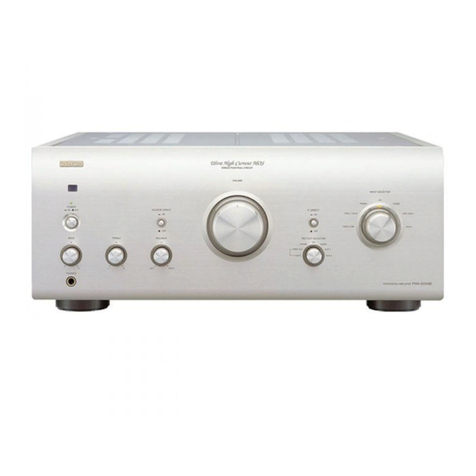
Denon POA-F100 User manual

DENON
SERVICE
MANUAL
MODEL
POA-F100
3
CHANNEL
POWER
AMPLIFIER
Hi-Fi
Component
PERSONAL
COMPONENT
SYSTEM
/
TRIPLE
POWER
AMPLIFIER
POA-F100
‘
—TABLE
OF
CONTENTS
—
SAFELY
PRECAUTIONS
ijcs5cicsstusbccatcescenssenscuicecdanseivacdustcesaneandoacs
baeectauusueds
aps
veneasvoueradrensunevansuadaSubsncnuaseeees
2
SPEGIFIGA
TIONS
ccacesssseisvaceancatesusanepacsen
tees
canedaeiensaseinevet
as
oacuateuinsdan
deste
ts
ausasaatnoeguecannauroussiasaenanatanes
tasanuaeees
2
DISASSEMBLY
siicieicshs
is
ested
esacs
capsid
cs
ehrtces
ereesnset
eancaatnaeacveaevatdnneioums
sudegeusnensueSerenatanaeatie
cede
uneveoeonns
3,4
PID
MIST
IMENT
scesceusace
see
coccas
pana
cecemuaaseapucased
vecen
cee
cnssaupseewsdccensearayavcner
eum
caeendceuetenabes
evap
evant
eeabi
de
goeetortueentans
5
BLOCK:
DIAGRAM
sicsccccgtctevoti
ca
tecsecas
Se
ccheusustuceceaestb
dae
etetiin
de
edveiuc
bad
tend
snaausias
uagpensdauedapestvestasouetanennensean@eeersn
6
BEVEL
DIAGRAM
sess
setecatecsccat
pic
htiascatenncils
Zeusds
cameesiockunicaypescatinesapataseyapansain
mcwes
cieongnatunipan
ces
esaatonaaanessnceeeeedeeeaenes
7
SEMIGONDUG
[ORG
-siiiveaseacrrvcateperticetccavciiamanieeseenedtnes
teongensetunssunewsumeuunauaeanncanseueeneducevernelveassusestusvieeadbicnniiiens
8
PRINTED
WIRING
BOARDS
wiviscecececezsnccietiapeanweaerecercnceaincecanddacnnstatsadeosoashevavenasssoasesnatnasniveaciauneeassnbnnciiewnncerss
9
NOTE-FOR
PAR
Te
EUS
Misxsscsctsctssecescscnanaidecinas
Saha
atsenecenaaroncaecs
cancucdieteaateedontannaes
ileeatheateusneacnanusdteeeceseatentiys
10
PARTS.LIST
OF
P.W.B.
UNIT
ASS
EY
vriiccncecsh
owes
sncishenavaecccastennsnsesueunsueesunenapsceassetisneraaleaaeaseanareesen
oossendee
10,11
EXPIEODED
VE
WW
sec
stericscosinaewonesss
ceauseeioecee
sales
guise
teiays
Gace
readied
ta
tdancic
casa
sehawtsntaais
seteeudene
sauce
sawbnancaaepees
cu
siauige
12
PARTS:
LIST
OF
EXPLODED:
VIEW
sssisssiicencthccsecctewcaciastbcancecaataoneuancagectececetin
dadvoncsedeecseeiassietaceaasseMeosoaueceens
13
PACKING:
VIEW
siisic
doses
den
Saatticsses
ae
ticanue
cussetievaxseenededietse
ue
cnuscucrte
cpa
cvs
oncbbocuduauetavpestauel
ou
cdesneh
suatseuusnanuewonsenneress
14
PARTS
LIST
OF
PACKING
&
ACCESSORIES
.............essssessssscsecesecceeersssenesssnsenssscsceascuenspessnasseeea
Haasenereease
14
WIFRING
DIAGN
wice
coisas
cctecoctacoarts
ee
dsseti
chaos
chan
toan
sete
nencde
ts
caieateta
sea
ce
eacees
ea
aeaniuutse
Mone
snaguguannnbewseuddasamsdeeeesceies
15
SCHEMATIC
DIAGRAM
sicsssenssocrssieolatectonsacett
ate
whaceotncecaes
aac
ctacebcee
nskeaedsacencudaupentese
ei
aeen
seued
ueuatanaatures
dete
santhtuiavars
16
NIPPON
COLUMBIA
CO.
LTD.
X0096
1
OO
ee
SAFETY
PRECAUTIONS
The
following
check
should
be
performed
for
the
continued
protection
of
the
customer
and
service
technician.
LEAKAGE
CURRENT
CHECK
Before
returning
the
unit
to
the
customer,
make
sure
you
make
either
(1)
a
leakage
current
check
or
(2)
a
line
to
chassis
resistance
check.
If
the
leakage
current
exceeds
0.5
milliamps,
or
if
the
resistance
from
chassis
to
either
side
of
the
power
cord
is
less
than
460
kohms,
the
unit
is
defective.
SPECIFICATIONS
Rated
output
power:
Total
harmonic
distortion:
Frequency
response:
Input
sensitivity:
Input
impedance:
S/N
ratio:
Output
terminals:
Power
supply:
Power
consumption:
Dimensions:
20
W
(6
Q/ohm
Load)
1
kHz,
T.H.D.
0.7
%
25
W
(6
Q/ohm
Load)
1
kHz,
T.H.D.
10
%
0.08
%
(-3
dB
at
rated
output,
8
Q/ohms,
1
kHz)
10
Hz
~
50
kHz
(+1,
-3
dB,
at
1
W)
460
mV
(Normal
in)
47
kQ/kohms
—
(Normal
in)
90
dB
(IHF,
A-weighting,
Normal)
Speakers:
6
~
16
Q/ohm
AC
230
V,
50
Hz
72W
270
(W)
x
84
(H)
x
266
(D)
mm
(including
control
knobs
and
feet)
3.9
kg
®
Specifications
and
contents
are
subject
to
change
without
notice
for
purposes
of
improvement.

DISASSEMBLY
(Follow
the
procedure
below
in
reverse
order
when
reassembling)
1.
Top
Cover
&
Front
Panel
Top
Cover
(1)
Remove
5
screws
(1)
fixing
the
Top
Cover.
(2)
Detach
the
Top
Cover
as
shown
in
the
arrow
direction.
(3)
Remove
4
screws
(2)
on
the
bottom
and
both
sides.
(4)
Disconnect
2P
LED
cable
and
2P
switch
cable
from
their
connector
bases.
(5)
Pull
the
Front
Panel
in
the
arrow
direction
with
releasing
Hooks
on
the
Front
Frame
from
the
Chassis,
and
it
comes
off
with
the
Front
Frame.
Front
Panel
2.
P.W.B.
on
Panel
FRONT
P.W.B.
Detach
the
Front
P.W.B.
to
the
arrow
direction
with
releasing
4
Hooks.
POA-F100
ma

mE
POA-F
100
3
Back
Chassis
(1)
Take
off
the
Cord
Stopper
from
the
Back
Chassis.
(2)
Remove
7
screws
(3),
and
detach
the
Back
Chassis
to
the
arrow
direction.
Cord
Stopper
Back
Chassis
ea
AMP
P.W.B.
(3)
Remove
4
screws
(4)
fixing
the
Heat
Sink
Bracket
L/R.
(4)
Disconnect
5P
and
8P
Connector
Cord
from
their
connector
bases.
(5)
Detach
the
Amp.
P.W.B.
with
the
Main
Heat
Sink.
MAIN
P.W.B.
(6)
Remove
2
screws
(5),
and
detach
the
Main
P.W.B.
Main
P.W.B.

SS
Re
eee
CS)
2.
1
OO
ras
ADJUSTMENT
Idling
Current
Required
measurement
equipment
and
tool:
*
DC
Voltmeter
¢
Small
screwdriver,
1mm
width
(—)
Preparation
(1)
Avoid
direct
blow
from
an
air
conditioner
or
an
electric
fan,
and
adjust
the
unit
at
normal
room
tempereture
15
°C
~
30
°C
(59
°F
~
86
°F).
(2)
Presetting
@
POWER
(Power
sourse
switch)
—
OFF
@
SPEAKER
(Speaker
terminal)
~
No
load
(Do
not
connect
speaker,
dummy
resistor,
etc.)
Note:
The
following
adjustment
should
be
performed
from
the
foil
side
of
the
P.W.B.
Adjustment
(1)
Remove
top
cover
and
set
SR201,
SR101,
SR301
on
Amp.
Unit
at
the
center
position.
(2)
Connect
DC
Voltmeter
to
test
points,
Lch:
J173(-),
J166(+),
Reh:
J163(-),
J154(+),
Och:
J147(-),
J129(+).
(3)
Connect
power
cord
to
AC
Line,
and
turn
power
switch
"ON".
(4)
Within
2
minutes
after
the
power
on,
turn
SR201
to
adjust
the
TEST
POINT
voltage
to
5.5
mV
+1.0
mV
DC.
(5)
Adjust
the
Variable
Resistors
of
other
channels
in
the
same
way.
AMP
P.W.B.
‘to
J154
(+)
J173
(-)
M1
‘TH.
J129
(+)
[1]
ey
®
SR101
SR201
SR301
Power
SW

eSneiteawweeeweNweweeeeseweewes
2 2
2 2
2
EEE
ESE
ES
OO
Oe
wwe
eeceemewcaseFanseeenasee,
Fo
eurererree
oe
eee
HOLOSLOWd
|
SSYNLVWHSdWSL
|
ee
i
er
ee
ee
ee
ee
ee
ltt
da
ee
|
tT
PSSST
TO
Sew
EER
EEE
EE
REE
REET
TERE
HOSE
RSE
E
BEBE
BOR
RO
ee
EO
OO
ew
Oy
PTT
ERO
OTERO
ew
EEE
EEE
HOT
E
OSE
SEES
ESE
HHEE
EES
THEHE
SESE
FES
EEE ERE
ERE
EHR
EE
SEDESESEE
EERE
EERO
td
ee
eee
eee
eee
eee
Pe
Pee
Pee
ee
ee
Pee
ee
eee
eee
eee
eee
ree
ee
eee
eee
eee
eee
eee
rere
re
rs
se)
:
ONIHOLIMS
AVIAH
YAL0310OWd
:
ee
eee
ee
eeoww
ne
es
ater
gee
eee
ee
ye
ee
ol
OO
eee
ew
ew
TEE
OTE
E
EEO
SEE
SHE
REESE
SE
EEO
SEH
HEED
EHH
EEO
ESE
SESEHRT
ERSTE
SESS
SEH
ERE
eee
ees
weewedeesbeanenseen
‘
sar
eney
us
eter
owe
Ba
wy
er
ee
eee
LNAdLNO
er
re)
errr)
Bannon
Seite
Sie
tee
'
HOUHIN
|
‘NOILOSLOWd:
:
QVOTHAAO:
i
ee
ee
ee
ee
ee
ae
ee
BLOCK
DIAGRAMS
1
2 3
4
5
z
;
POWER
SW
Oo
:
>
7
igo
;
©
O
sO
i—i2
-—2O
a
LL
>
O
:
“OQ
UW
:
—!
O
<
Tr.
7)
=
owe
a
OO
:
—
Qo
LO
3
rit
a.
Ee
9
:
<
aa
:
=)
:
uu
Lu
W.
—~12V
sl
Tf
=O
©
©

(6SSGSz2/68EcdSz)
dWV
4345Nd
dINV
HSMOd
LEVEL
DIAGRAM
0
0
v
u
q
0
a
<=
(SU
AWO9P)
cetera
ae
rang
pa
ey
nae
aera
apo
(WHO
9/MGZ2)
ASZ
Zl
gPpor
LNO
dS
GPSr'
sc
gpod
ae
]
|
GPO0e
|
|
SUUAWOSP:ALIAILISNAS
LNdNI
INO
[k
©)
INO
+s
[hi
OTS
al
USI
©)
u-S

me
POA-F100
SEMICONDUCTORS
@iCc
NJMO074D
(1C101)
@
TRANSISTORS
DTC114YS
NPN
Series
Ri
C
B
aan
Ee
B
(Base)
eee
ee
C
(Collector)
4.7kohm
E
(Emitter)
@
DIODES
18$133
1N4007
Yellow
—té-
Black
—té
OUTPUT
4
INV.
INPUT
4
NON-INV.
INPUT
4
OUTPUT
1
|
1
|
INV.
INPUT
1
/\
NON-INV.
INPUT
1
5
antl
Vec
|
4
|
VEE
NON-INV.
INPUT
2
[5
|
NON-INV.
INPUT
3
INV.
INPUT
2
al
Sy
V7
le
INV.
INPUT
3
OUTPUT
2
|
8
|
OUTPUT
3
KSA992F
2804137
2SB1559
KSC1845F
2SD2389
KTA1266
KTC3198
B
(Base)
C
(Collector)
F
(Emitter)
E
(Emitter)
C
(Collector)
B
(Base)
B
(Base)
C
(Collector)
E
(Emitter)
MTZJ12B
D3SB20
MTZJ6.2B
Black
——¢—

ll
|
$
Ney
z
i>
ee
aie
foe
ALLO
ORY
ER
EA
POO
SOE
NI
7€2G-86231-088-8
me
it
=
Al
SH-B
A
u
-
7
es,
at
=
3°.
-688—

ml
POA-F
100
10
NOTE
FOR
PARTS
LIST
some
case
supplying
of
part
may
be
refused.
WARNING:
@
Resistors
Ex..
RN
14K
2E
182
G
FR
Type
Shape
Power
Resist-
Allowable
Others
and
per-
ance
—
error
|
formance
|
:
Carbon
: : :
Pulse-resistant
type
:
Composition
:
:
:
Low
noise
type
:
Metal
oxide
film
:
Non-burning
type
:
Winding
:
:
:
Fuse-resistor
:
Metal
film
:
:
:
Lead
wire
forming
:
Metal
mixture
*
Resistance
18
2
=>
1800
ohm
=
1.8
kohm
Indicates
number
of
zeros
after
effective
number.
2-digit
effective
number.
e
Units:
ohm
1R
2
=>
1.2
ohm
t
4_______
1
-digit
effective
number.
2-digit
effective
number,
decimal
point
indicated
by
R.
e
Units:
ohm
@
Part
indicated
with
the
mark
"©"
are
not
always
in
stock
and
possibly
to
take
a
long
period
of
time
for
supplying,
or
in
@
When
ordering
of
part,
clearly
indicate
"1"
and
"I"
(i)
to
avoid
mis-supplying.
@
Ordering
part
without
stating
its
part
number
can
not
be
supplied.
@
Part
indicated
with
the
mark
"x"
is
not
illustrated
in
the
exploded
view.
@
Not
including
Carbon
Film
+5%,
1/4W
Type
in
the
P.W.Board
parts
list.
(Refer
to
the
Schematic
Diagram
for
those
parts.)
Parts
marked
with
this
symbol
A\
Ii
have
critical
characteristics.
Use
ONLY
replacement
parts
recommended
by
the
manufacturer.
@
Capacitors
Ex:
CE
04W
1H
2R2
M
BP
Type
Shape
Dielectric
Capacity
Allowable
Others
and
per-
strength
error
|
formance
:
Aluminum
foil
:
High
stability
type
electrolytic
:
Aluminum
solid
electrolytic
:
Tantalum
electrolytic
:
Film
:
Ceramic
Qo
mn
:
Non-polar
type
:
Ripple-resistant
type
:
For
change
and
discharge
:
For
assuring
high
frequency
:
UL
part
:
CSA
part
:
UL-CSA
type
:
Lead
wire
forming
:
Ceramic
:
Oil
:
Mica
:
Metallized
:
Metallized
J:
K:
M:
2:
P:
Cc:
D:
*
Capacity
(electrolyte
only)
22
2
=>
2200uF
Indicates
number
of
zeros
after
effective
number.
2-digit
effective
number.
e
Units:
pF.
2R2
5
=~
2.2uF
1-digit
effective
number.
2-digit
effective
number,
decimal
point
indicated
by
R.
e
Units:
pF.
*
Capacity
(except
electrolyte)
2.2
2
=
2200pF=0.0022uF
t
4—
(More
than
2)—Indicates
number
of
zeros
after
effective
number.
2-digit
effective
number.
e
Units:
pF.
22
1
=>
220pF
t
t
(0
or
1)
Indicates
number
of
zeros
after
effective
number.
2-digit
effective
number.
e
Units:
pF.
e
When
the
dielectric
strength
is
indicated
in
AC,
"AC"
is
included
after
the
dieelectric
strength
value.
PARTS
LIST
OF
P.W.B.
UNIT
MAIN
P.W.B.
ASS'Y
SEMICONDUCTORS
GROUP
C101
960
0218
905
|IC
NJM074D
J121074000010
J5000992F0050
J5021845F0000
J5000992F0050
J5021845F0000
Transistor
KSA992F
Transistor
KSC1845F
Transistor
KSA992F
Transistor
KSC1845F
Q101,102
Q103,104
Q105
Q109
960
0196
205
960
0196
506
960
0196
205
960
0196
506
Transistor
KSA992F
Transistor
KSC
1845F
Transistor
KSA992F
Transistor
KSC1845F
J5000992F0050
J5021845F0000
J5000992F0050
J5021845F0000
Q201,202
Q203,204
Q205
Q209
960
0196
205
960
0196
506
960
0196
205
960
0196
506
Transistor
KSA992F
Transistor
KSC
1845F
Transistor
KSA992F
Transistor
KSC
1845F
J5000992F0050
J5021845F0000
J5000992F0050
J5021845F0000
960
0196
205
960
0196
506
960
0196
205
960
0196
506
Q301,302
Q303,304
Q305
Q309
Q401
960
0005
105
|
Transistor
KTA1266Y
J5001266Y0050
Q402
960
0196
506
|
Transistor
KSC1845F
J5021845F0000
403,404
|
960.0005
202
|
Transistor
KTC3198
(Y)
J5023198Y0000
Q405
960
0196
904
|
Transistor
DTC114YS
(NPN)
|
J6020114Y0050
Q406,407
|
960
0196
205
|
Transistor
KSA992F
J5000992F0050
Q408
960
0005
202
|
Transistor
KTC3198
(Y)
J5023198Y0000
Q601,602
|
960
0196
506
|
Transistor
KSC1845F
J5021845F0000
Q603
960
0196
205
|
Transistor
KSA992F
J5000992F0050
Q604,605
|
960
0005
202
|
Transistor
KTC3198
(Y)
J5023198Y0000
D101~103
|
963
0020
309
|
Diode
1SS133T
K000013300520
D201~203
|
963
0020
309
|
Diode
1SS133T
K000013300520
K000013300520
D301~303
Diode
1$S133T
963
0020
309
D401,402
|
963
0020
309
Diode
1$S133T
K000013300520
960
0039
508
963
0058
407
D501
D502~507
Diode
D3SB20/DBF40C
Diode
1N4007
K047004000010
K000400700520
D601
Diode
1$S133T
K000013300520
963
0020
309
ZD401,601
|
963
0058
601
|
Zener
diode
MTZJ12B
K06012R044520
ZD602
960
0095
704
|
Zener
diode
MTZJ6.2B
K06006R244520
LED601,602
960
0219001
|LED
HL30CNB
RED
K500032000090
RESISTORS
GROUP
|
R109
Metal
film
220
ohm
1/4W
C060022163050
R111
Metal
film
270
ohm
1/4W
(NB)
|C060027163050
R112
Metal
film
220
ohm
1/4W
C060022163050
960
9004
301
244
2043
982
R117,118
R119,
120
R127
R128
963
9003
068
R209
R211
R212
R217,218
|
960
9004
301
R219,220
|
244
2043
982
R227
244
2043
937
R228
963
9003
068
R309
R311
R312
R317,318
|
960
9004
301
R319,320
|
244
2043
982
R327
244
2043
937
R328
963
9003
068
R410
960
9003
807
R501,502
|
960
9004
301
R606
SR101,201
|
960
0221
109
SR301
960
0221
109
244
2043
937
C06004
7063050
C060R22065070
C060010065050
C0604R7063050
Metal
film
47
ohm
1/4W
Metal
oxide
0.22
ohm
1W
Metal
film
10
ohm
1W
(NB)
Metal
film
4.7
ohm
1/4W
(NB)
Metal
film
220
ohm
1/4W
C060022163050
Metal
film
270
ohm
1/4W
(NB)
|
060027163050
Metal
film
220
ohm
1/4W
——-
|
C060022163050
Metal
film
47
ohm
1/4W
C060047063050
Metal
oxide
0.22
ohm1W
—_
|
CO60R22065070
Metal
film
10
ohm
1W
(NB)
—
|
C060010065050
Metal
film
4.7
ohm
1/4W
(NB)
|
C0604R7063050
Metal
film
220
ohm
1/4W
C060022
163050
Metal
film
270
ohm
1/4W
(NB)
|
C060027163050
Metal
film
220
ohm
1/4W
C060022163050
Metal
film
47
ohm
1/4W
C060047063050
Metal
oxide
0.22
ohm
1W
C060R22065070
Metal
film
10
ohm
1W
(NB)
C060010065050
Metal
film
4.7
ohm
1/4W
(NB)
|
C0604R7063050
C060010163050
Metal
film
100
ohm
1/4W
C060047063050
Metal
film
47
ohm
1/4W
Metal
film
2.2
kohm
1/4W
(NB)
|
C060022263520
C541102115000
Semi
fixed
resistor
1
kohm
Semi
fixed
resistor
1
kohm
0541102115000
CAPACITORS
GROUP
|
C101
C102
C103
C104
C105
C106
C107
C108
C109
C110
C111
C112
C113
C114,115
|
9630021
900
C116
C117
C120
C121
C201
D001680067520
D040010087080
D005101177520
D005331277520
D005101177520
D040101082060
D000820167050
D040010086060
D0Q018R2077530
D004221067060
D040220085050
D000820167050
D004223597050
D02047306C060
D02047206C060
D004103277050
D0013R3077520
D004472277050
Ceramic
68pF/50V
Electrolytic
114F/50V
Ceramic
100pF/50V
Ceramic
330pF/50V
Ceramic
100pF/50V
Electrolytic
100.F/10V
Ceramic
82pF/50V
Electrolytic
1.F/100V
Ceramic
8.2pF/50V
Ceramic
220pF/50V
Electrolytic
22u.F/35V
Ceramic
82pF/50V
Ceramic
0.022F/50V
Mylar
film
0.047,1F/100V
Mylar
film
0.00471F/100V
Ceramic
0.01,F/50V
Ceramic
3.3pF/50V
Ceramic
0.0047pF/50V
Ceramic
68pF/50V
D001680067520

C202
C203
C204
C205
C206
C207
C208
C209
C210
C211
C212
C213
214,215
C216
C217
C220
C221
C301
C302
C303
C304
C305
C306
C307
C308
C309
C310
C311
C312
C313
C314,315
C316
|
C317
C320
~
C321
C401
C402
C403
C404
C405
C406
C501°
504
C505,506
C507,508
C509,510
C511
C512,513
C515,516
C517
963
0021
900
963
0021
900
963
9003
152
Electrolytic
1,4F/50V
Ceramic
100pF/50V
Ceramic
330pF/50V
Ceramic
100pF/50V
Electrolytic
100..F/10V
Ceramic
82pF/50V
Electrolytic
1.F/100V
Ceramic
8.2pF/50V
Ceramic
220pF/50V
Electrolytic
22..F/35V
Ceramic
82pF/50V
Ceramic
0.022uF/50V
Mylar
film
0.047uF/100V
Mylar
film
0.00471F/100V
Ceramic
0.01,:F/50V
Ceramic
3.3pF/50V
Ceramic
0.0047pF/50V
Ceramic
68pF/50V
Electrolytic
1p.F/50V
Ceramic
100pF/50V
Ceramic
330pF/50V
Ceramic
100pF/50V
Electrolytic
100F/10V
Ceramic
82pF/50V
Electrolytic
1uF/100V
Ceramic
8.2pF/50V
Ceramic
220pF/50V
Electrolytic
22uF/35V
Ceramic
82pF/50V
Ceramic
0.022uF/50V
Mylar
film
0.047pF/100V
Mylar
film
0.0047,1F/100V
Ceramic
0.01pF/50V
Ceramic
3.3pF/50V
Ceramic
0.0047,1F/50V
Mylar
film
0.01,1F/100V
Electrolytic
10.F/35V
Electrolytic
220uF/6.3V
Electrolytic
220uF/25V
Electrolytic
100.F/35V
Mylar
film
0.068,.F/100V
Ceramic
0.01,1F/500V
Electrolytic
4700u.F/50V
Electrolytic
470,.F/35V
Ceramic
0.01pF/500V
Metalized
0.1F/250V
Electrolytic
100.F/35V
Electrolytic
47F/50V
D040010087080
D005101
177520
D005331277520
D005101177520
D040101082060
D000820167050
D040010086060
D0018R2077530
D004221067060
D040220085050
D000820167050
D004223597050
D02047306C060
D02047206C060
D004103277050
D0013R3077520
D004472277050
D001680067520
D040010087080
D005101177520
D005331277520
D005101177520
D040101082060
D000820167050
D040010086060
D0018R2077530
D004221067060
D040220085050
D000820167050
D004223597050
D02047306C060
D02047206C060
D004103277050
D0013R3077520
D004472277050
D02010306C060
D040100085
100
D040221081050
D04022
1084060
D040101085050
D02068306C060
D00410359D050
D040472087000
|D040471085100
D00410359D050
D02310407H150
D040101085050
D040470087060
960
0177
208
|
Ceramic
0.00471F/
250V
(AC)
|
D00847208K03D
|
Ref.No.
|
PartNo.
|
PartName
|
Remarks
Electrolytic
33.F/16V
Electrolytic
10F/35V
Electrolytic
10F/16V
C601
,602
C603
C604
OTHER
PARTS
P
a'ty
GROU
CLAMP501
CN101
CNS501
CN503
CN504
CN505
CN506
CN601
CN602
JACK501
JACK502
JP101
JP501
JP506
JP601
L101,201
L301
960
0213
023
960
0118
801
960
0123
304
960
0118
908
960
0128
804
960
0123
304
960
0219
302
960
0123
207
960
0221
002
960
0218
808
960
0219
904
960
0219
917
960
0219
221
960
0219
920
960
0005
008
960
0005
008
960
0181
702
960
0219
409
Wire
clamp
5P
connector
base
8P
connector
base
2P
connector
base
2P
connector
base
6P
connector
base
2P
connector
base
2P
connector
base
3P
connector
base
SP
pin
jack
6P
speaker
terminal
5P
connector
cord
8P
connector
cord
2P
connector
cord
2P
connector
cord
Inductor
0.15H
Inductor
0.15H
Relay
(G5PA-28
24V)
Push
switch
D042330083050
D040100085
100
0040100083100
4330000120000
L101530150510
L102526700800
L104353280200
L108039602010
L102526700600
L104353280200
L102526800200
L102526700300
G606030164030
G596040340000
L000085050010
L000900080010
L000301020010
L000401020040
D330R15000000
D330R15000000
G680240502020
G000000050010
1
POA-F
100
|
11

POA-F100
EXPLODED
VIEW
12

mgm
POA-F100
PACKING
VIEW
PARTS
LIST
OF
PACKING
&
ACCESSORIES
[Ret.No.
|
PartNo.
|
PartName
|
Remarks
[ay
Ref-No.
|
PartNo.
|
PartName
|
__
Remarks
_|a'ty
1-1
960
0218
413
|
Instruction
manual
5707210370000
1
*
Control
label
5500014920010
1-2
*
*
960
0219
108
|
3P
pin
cord
L063310200000
EAN
label
5507005000010
1-3
|960
0107
809
|
Poly
bag
6337000240010
for
Gold
model
2
|960
0116
007
|
Cushion
ass'y
6230210014000
EAN
label
5507005000020
4
|960
0116
104
|
Set
poly
bag
6337200029010
for
Black
model
5
—
POA-F100
6
{960
0218
510
|
Carton
case
6007210010000
14

POA-F100
ml
PARTS
LIST
OF
EXPLODED
VIEW
|
Ref.No.
|
PartNo.
|
PartName
|
Remarks
_|a'ty
oe
ee
a
960
0218
617
|
Main
P.W.B
ass'y
7025MM9901010
Main
P.W.B
AMP
P.W.B
LED
P.W.B
POWER
SW
P.W.B
Power
button
960
0108
604
|
Screw
(2S
3x8
BK/BH)
_|
B020030083B10
960
9008
006
|
Screw
(2S
3x8
BK/FH)
|
B020030083F10
963
0048
404
|
Screw
(2S
3x16
ZNY/HH)
|
1507041146010
963
0018
007
|
Screw
(2S
3x8
ZNY/BH)
|
B020030081B10
960
9008
417
|
Screw
(3S
4x8
ZNY/BH)
|
B028940081B10
5097210791000
for
Gold
model
5097210791100
for
Black
model
5630210008000
for
Gold
model
5630210008010
for
Black
model
3067210048300
for
Gold
model
3067210048310
for
Black
model
3217210101000
for
Gold
model
3217210101100.
for
Black
model
G000000050010
SW501
5160210053000
K500032000090
LED601,602
moo
wo
Y
960
0208
009
960
0208
012
|
Power
button
960
0115
707
|
DENON
badge
960
0115
710
|
DENON
badge
960
0217
809
|
Front
panel
960
0217
812
|
Front
panel
960
0218
109
|
Front
frame
960
0218
112
|
Front
frame
960
0219
409
|
Push
switch
LED
indicator
LED
HL30CNB
RED
960
0218
206
960
0219
001
960
0218
714
|
Power
trans
8200660550050
—
Wire
clamp
4330040213010
960
0219
506
|
Trans
cushion
4050210195000
—
Heat
sink
2120210198000
960
0219
603
|
Heat
sink
bracket
L
4010210536000
PWB
bracket
Posistor
Heat
sink
bracket
R
Top
cover
4010055806010
F320550001010
4010210546000
3000210006300
for
Gold
model
3000210006400
for
Black
model
4010210556000
4050210215000
4050020075010
4007000061010
4000210001000
3200210086200
4070001601010
G596040340000
JACK502
G606030164030
JACK501
3207210016400
4380040162010
960
0221
604
960
0221
206
960
0219
616
960
0217
702
960
0217
715
|
Top
cover
960
0221
303
960
0219
700
960
0003
505
960
0003
408
960
0115
008
960
0221
507
960
0003
301
960
0218
808
Safty
bracket
Main
cushion
Foot
cushion
Foot
Foot
Chassis
PCB
supporter
6P
speaker
terminal
—_~
Am
=
AO
AP
HP
— —
960
0221
002
|
3P
pin
jack
960
0217
919
960
0135
305
Back
panel
Cord
stopper
13

[ZZ
POA-F100
~
SCHEMATIC
DIAGRAM
16
aes
KSC1845
noes
ZB
fal
s[ulul—]
spies
eecrrznneneeanrenaneceneeaaaaneaeeeeneeeeaesaneeaannaneaaneeaeoenacaveaneeeeneaagatseevenavneeennsnartenzrveeaneneaesea
py
af
wf!
eaecununnnaeeanawaeaernewnevenenragy
!
ii
«
:
2
NO
3}
ree
a
L270)
Oise
ze
@.
15s
iT
EN
4
R228
on?
Rance
Lt
ENTE
Ft
on7
1174
A
5
%
Yh
JOU
q
Sr
,
i
S-F
Oo
@7H-M
RL27
cis4
C303
190P
BSawewneaan
hee
neazawmeenrmeowmeocewne
ese
See
ee
seen
swan
aneeseweveeseawreaunnnanwraavnan
jaa}
wfartuny
afuslol—
|
Pcer
wavwhzhernancnaace
e@eaoanatvraaoeereeae
ae
|
amktncen
Ui
228
0582
1N4eR4
BCS!7
4
ue
00/5
bse)
iweoed
ra
Hf
168/35
TEMPERATURE
PROTECTION
:
:
SF
BLINE
a
See
BY
ae
ee
8
LINE
~15V
SCHEMATIC
DIAGRAM
—--—
MAIN
UNIT
:
7
AMP
UNIT
LED
UNIT
POWER
SW
UNIT
SIGNAL
(S-Lch)
NOTICE
ALL
RESISTANCE
VALUES
IN
OHM.
k=1,
000
OHM
M=1,000,000
OHM
ALL
CAPACITANCE
VALUES
I
N
MICRO
F-ARAD.
P=MICRO-MICRO
FARAD
EACH
VOLTAGE
AND
CURRE
NT
ARE
ME-ASUERD
AT
NO
SIGNAL
INPUT
CONDITION.
CIRCUIT
AND
PARTS
ARE
SUBJECT
TO
CHANGE
WITHOUT
PRIOR
NOTICE.
WARNING:
Parts
marked
with
this
symbol
AEEShave
critical
characteristics.
Use
ONLY
replacement
parts
recommended
by
the
manufacture.
CAUTION:
Before
retuming
the
unit
to
the
customer,
make
sure
you
make
either
(1)
a
leakage
current
check
or
(2)
a
line
to
chasssis
resistance
check.
If
the
leakage
current
exceeds
0.5
milliamps,
or
if
the
res
stance
from
chassis
to
either
side
of
the
power
card
is
less
than
460
kohms,
the
unit
is
defective.
WARNING:
DO
NOT
retum
the
unit
to
the
customer
uretil
the
problem
is
located
and
corrected.

WIRING
DIAGRAM
1
POA-F100
om
3
4 5
6
7
8
1g
—
OC
[
ot
bo
a
A
ieee
ae
[Po
Wen
Ldheueu-
eure
DT
T
l
li
at
air
TRANS
2‘ST
i.
ae
CN503
CN504_
-JP506
B
~
fe
z
O
2
<t
x
=
JP101
z
9
‘
Le
LED
2P
WIRE
ae
O
Dé
+
reesees
re
eS
OT
Ca)
0
0'O
oe
<
C
©
Z
=
~*
=<
Fo
|
se
wi
Lu
s
oP)
5
[je
a
Co
;
WW
[
|
|
JP501
o
3
Ss
CN602
oO
To)
4
D
O00
O
END
fs
@
1
o
00
Co
POWER
S/W
BOARD
LED
BOARD
7020-06031
-000-0
CN101
LOONO
°
f\
aN
van
OO.
Cae
OO
7020-06031
-000-0
O
0
Ge
OO
4.
|
oe
al
15
Table of contents
Other Denon Amplifier manuals

Denon
Denon PMA-30 User manual

Denon
Denon PMA-360 User manual

Denon
Denon AVC-A1H User manual

Denon
Denon AVC-S660H User manual

Denon
Denon POA-A1HDCI User manual

Denon
Denon PRA-S1 User manual

Denon
Denon AVC-X8500H User manual

Denon
Denon PMA-2020AE User manual

Denon
Denon PMA-2010AE User manual

Denon
Denon PMA-A100 User manual

Denon
Denon AVR-3803 User manual

Denon
Denon PMA-710AE User manual

Denon
Denon AVC-X6700H User manual

Denon
Denon PMA-50 User manual

Denon
Denon AVP-A1HDCI - Ultra Reference A/V Network Streaming... User manual

Denon
Denon AVC-X3700H User manual

Denon
Denon PMA-2000 IV - Amplifier User manual

Denon
Denon PMA-700AE User manual

Denon
Denon PMA-700V User manual

Denon
Denon PMA-495R Quick start guide