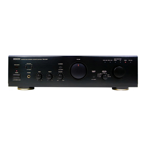
Denon PMA-360 User manual

SERVICE
MANUAL
MODEL
PMA-360
INTEGRATED
STEREO
AMPLIFIER
CONTENTS
OPERATING
INSTRUCTIONS
BLOCK
AND
LEVEL
DIAGRAM
METHOD
OF
ADJUSTMENTS
REMOVAL
OF
EACH
SECTION
SEMICONDUCTORS
PRINTED
WIRING
BOARD
WIRING
DIAGRAM
PRINTED
WIRING
BOARD
PARTS
LIST
EXPLODED
VIEW
OF
CHASSIS
AND
CABINET
PARTS
LIST
OF
EXPLODED
VIEW
SCHEMATIC
DIAGRAM
NIPPON
COLUMBIA
CO.
LTD.
|
©
)
|
Hi-Fi
Integrated
Stereo
Amplifier

a
PIVIA-360
CAUTION
RISK
OF
ELECTRIC
SHOCK
DO
NOT
OPEN
CAUTION:
TO
REDUCE
THE
RISK
OF
ELECTRIC
SHOCK,
DO
NOT
REMOVE
COVER
(OR
BACK).
NO
USER
SERVI-
CEABLE
PARTS
INSIDE.
REFER
SERVICING
TO
QUALIFIED
SERVICE
PERSONNEL.
WARNING:
TO
REDUCE
THE
RISK
OF
FIRE
OR
ELECTRIC
SHOCK,
DO
NOT
EXPOSE
THIS
APPLIANCE
TO
RAIN
OR
MOISTURE.
The
lightning
flash
with
arrowhead
symbol,
within
an
equilateral
triangle,
is
intended
to
alert
the
user
to
the
presence
of
uninsulated
“dangerous
voltge”
within
the
product’s
enclosure
that
may
be
of
sufficient
magnitude
to
constitute
a
risk
of
electric
shock
to
persons.
The
exclamation
point
within
an
equilateral
triangle
is
intended
to
alert
the
user
to
the
presence
of
important
operating
and
maintenance
(servicing)
instructions
in
the
literature
accompanying
the
appliance.
CAUTION
ATTENTION
TO
PREVENT
ELECTRIC
SHOCK
DO
NOT
USE
THIS
(POLARI-
POUR
PREVENIR
LES
CHOCS
ELECTRIQUES
NE
PAS
UTILISER
ZED)
PLUG
WITH
AN
EXTENSION
CORD,
RECEPTACLE
OR
CETTE
FICHE
POLARISEE
AVEC
UN
PROLONGATEUR
UNE
OTHER
OUTLET
UNLESS
THE
BLADES
CAN
BE
FULLY
INSER-
PRISE
DE
COURANT
OU
UNE
AUTRE
SORTIE
DE
COURANT,
TED
TO
PREVENT
BLADE
EXPOSURE.
SAUF
SI
LES
LAMES
PEUVENT
ETRE
INSEREES
A
FOND
SANS
EN
LAISSER
AUCUNE
PARTIE
A
DECOUVERT.
SAFETY
INSTRUCTIONS
Read
Instructions
—
All
the
safety
and
operating
instructions
should
be
read
before
the
appliance
is
operated.
Retain
Instructions
—
The
safety
and
operating
instructions
should
be
retained
for
future
reference.
Heed
Warnings
—
All
warnings
on
the
appliance
and
in
the
operating
instructions
should
be
adhered
to.
Follow
Instructions
—
All
operating
and
use
instruc-
tions
should
be
followed.
Water
and
Moisture
—
The
appliance
should
not
be
used
near
water
—
for
example,
near
a
bathtub,
washbowl,
kitchen
sink,
laundry
tub,
in
a
wet
basement,
or
near
a
swimming
pool,
and
the
like.
Carts
and
Stands
—
The
appliance
should
be
used
only
with
a
cart
or
stand
that
is
recommended
by
the
manufacturer.
6A.
An
appliance
and
cart
combination
should
be
moved
with
care.
Quick
stops,
excessive
force,
and
uneven
surfaces
may
cause
the
appliance
and
cart
combination
to
overturn.
7.
Wall
or
Ceiling
Mounting
—
The
appliance
should
be
mounted
to
a
wall
or
ceiling
only
as
recommended
by
the
manufacturer.
8.
Ventilation
—
The
appliance
should
be
situated
so
that
its
location
or
position
does
not
interfere
with
its
proper
ventilation.
For
example,
the
appliance
should
not
be
situated
on
a
bed,
sofa,
rug,
or
similar
surface
that
may
block
the
ventilation
openings;
or,
placed
in
a
built-in
installation,
such
as
a
bookcase
or
cabinet
that
may
impede
the
flow
of
air
through
the
ventilation
openings.
9.
Heat
—
The
appliance
should
be
situated
away
from
heat
sources
such
as
radiators,
heat
registers,
stoves,
or
other
appliances
(including
amplifiers)
that
produce
heat.

10.
11.
12.
13.
14.
15.
16.
SERVICE
ENTRANCE
EQUIPMENT
POWER
SERVICE
GROUNDING
ELECTRODE
SYSTEM
{e.9.
interior
metal
water
pipe)
¢
$2898
Power
Sources
—
The
appliance
should
be
connected
to
a
power
supply
only
of
the
type
described
in
the
operating
instructions
or
as
marked
on
the
ap-
pliance.
Grounding
or
Polarization
—
The
precautions
that
should
be
taken
so
that
the
grounding
or
polarization
means
of
an
appliance
is
not
defeated.
Power-Cord
Protection
—
Power-supply
cords
should
be
routed
so
that
they
are
not
likely
to
be
walked
on
or
pinched
by
items
placed
upon
or
against
them,
paying
particular
attention
to
cords
at
plugs,
conve-
nience
receptacles,
and
the
point
where
they
exit
from
the
appliance.
Protective
Attachment
Plug
—
The
appliance
is
equip-
ped
with
an
attachment
plug
having
overload
pro-
tection.
This
is
a
safety
feature.
See
Instruction
Manual
for
replacement
or
resetting
of
protective
device.
lf
replacement
of
the
plug
is
required,
be
sure
the
service
technician
has
used
a
replacement
plug
specified
by
the
manufacturer
that
has
the
same
overload
protection
as
the
original
plug.
Cleaning
—
The
appliance
should
be
cleaned
only
as
recommended
by
the
manufacturer.
Power
Lines
—
An
outdoor
antenna
should
be
located
away
from
power
lines.
Outdoor
Antenna
Grounding
—
If
an
outside
antenna
is
connected
to
the
receiver,
be
sure
the
antenna
system
is
grounded
so
as
to
provide
some
protec-
tion
against
voltage
surges
and
built
up
static
charges.
Section
810
of
the
National
Electrical
Code,
ANSI/NFPA
No.
70-1984,
provides
information
with
respect
to
proper
grounding
of
the
mast
and
suppor-
FIGURE
A
EXAMPLE
OF
ANTENNA
GROUNDING
ACCORDING
TO
NATIONAL
ELECTRICAL
CODE
INSTRUCTIONS
CONTAINED
IN
ARTICLE
810
-
“RADIO
AND
TELEVISION
EQUIPMENT”
SERVICE
ENTRANCE
CONDUCTORS
id
GROUND
CLAMPS
BONDING
JUMPERS
OPTIONAL
ANTENNA
GROUNDING
ELECTRODE
ORIVEN
8
FEET
(2.44
m)
INTO
THE
EARTH
d
iF
REQUIRED
BY
LOCAL
CODES.
SEE
NEC
SECTION
810
—
21(f).
b;
GROUND
WIRES.
D
PMA-360
ting
structure,
grounding
of
the
lead-in
wire
to
an
antenna
discharge
unit,
size
of
grounding
conduc-
tors,
location
of
antenna-discharge
unit,
connection
to
grounding
electrodes,
and
requirements
for
the
grounding
electrode.
See
Figure
A.
17.
Nonuse
Periods
—
The
power
cord
of
the
appliance
should
be
unplugged
from
the
outlet
when
left
unused
for
a
long
period
of
time.
18.
Object
and
Liquid
Entry
—
Care
should
be
taken
so
that
objects
do
not
fall
and
liquids
are
not
spilled
into
the
enclosure
through
openings.
19.
Damage
Requiring
Service
—
The
appliance
should
be
serviced
by
qualified
service
personnel
when:
A.
The
power-supply
cord
or
the
plug
has
been
damaged;
or
B.
Objects
have
fallen,
or
liquid
has
been
spilled
into
the
appliance;
or
C.
The
appliance
has
been
exposed
to
rain;
or
D.
The
appliance
does
not
appear
to
operate
normal-
ly
or
exhibits
a
marked
change
in
performance;
or
E.
The
appliance
has
been
dropped,
or
the
enclosure.
damaged.
20.
Servicing
—
The
user
should
not
attempt
to
service
the
appliance
beyond
that
described
in
the
operating
instructions.
All
other
servicing
should
be
referred
to
qualified
service
personnel.
STANDOFF
INSULATORSD
MAST
ANTENNA
LEAO-IN
WIRE
ANTENNA
Gaon
9
Use
No.
10
AWG
(5.3
mm?)
copper,
No.
8
AWG
(8.4
mm?)
aluminum,
No.
17
AWG
(1.0
mm?)
copper-clad
steel
or
bronze
wire,
or
larger,
as
a
ground
wire.
TO
EXTERNAL
ANTENNA
b
TERMINALS
OF
PRODUCT
Secure
antenna
lead-in
and
ground
wires
to
house
with
stand-off
insulators
spaced
from
4-6
feet
(1.22-1.83
m)}
apart.
Mount
antenna
discharge
unit
as
close
as
possible
to
where
lead-in
enters
house.
Use
jumper
wire
not
smatier
than
No.
6
AWG
(13.3
mm7?}
copper,
or
the
equivalent,
when
a
separate
antenna-
grounding
electrode
is
used.
See
NEC
Section
810-21
{j).
3

a
PVIA-360
Die
Deutsche
Bundespost
informiert
Sehr
geehrter
Rundfunktellnehmer,
Dieses
Gerit
ist
von
der
Deutschen
Bundespost
als
Ton-
bzw.
Ternseh-Rund-funkempfanger
bzw.
als
Komponente
einer
solchen
Antage
(Tuner,
Verstarker,
aktive
Lautsprecherbox,
Frenseh-Monitor
u.
dgl.)
zugelassen.
Is
entspricht
den
zur
Zeit
geltenden
Technischen
Vorschriften
und
ist
zum
Nachweis
dafir
mit
dem
Zulassungszeichen
der
Deutschen
Bundespost
gekennzeichnet.
Bitte
Gberzeugen
Sie
sich
selbst.
Dieses
Ger&t
dart
im
Rahmen
der
“Aligemeingenehmigung
fir
das
Irrichten
und
Betreiben
von
Ton-
und
Fernseh-Rundfunkempfangern”™
in
der
Bundesrepublik
Deutschland
betrieben
werden.
Beachten
Sie
aber
bitte,
da@
autgrund
dieser
Genehmigung
hur
fir
die
Allgemeinheit
bestimmte
Sendungen
und
solche,
fir
die
ebanfalls
eine
Allgemeine
Empfangsgenehmigung
erteiit
worden
ist*).
empfangen
und
wiedergegeben
werden
dirfen.
Wer
unbefugt
andere
Sendungen
{z.
B.
des
Polizeifunks,
des
Mobiifunks)
emfangt
und
wiedergibt,
verst6Bt
gegen
die
Genehmigungsauflagen
und
macht
sich
daher
nach
§
15,
Absatz
2a
des
Gesetzes
ber
Fernmeldeanlagen
strafbar.
Die
Kennzeichnung
mit
dem
Zulassungszeichen
bietet
Ihnen
die
Gew&hr,
da&
dieses
Gerat
keine
anderen
ordnungsgema®6
errichteten
und
betriebenen
elektrischen
Anlagen
stért.
Der
Zusatzbuchstabe
S**}
baim
Zulassungszeichen
besagt
auBerdem,
da&
das
Gerét
gegen
stérendue
Beeinflussungen
durch
andere
ordnungsgemaB
errichtete
und
bdetriebene
elektrische
Anlagen
weitgehend
unemofinolich
ist,
Geréte
ohne
den
Zusatz
S$
sind
nicht
besonders
sicher
gegen
Beeinflussungen.
Sollten
bei
Geraten
mit
dem
Zusatz
S
ausnahmsweise
trotzdem
Beeinflussungen
auftreten,
oder
wenn
Sie
Fragen
haben,
so
wenden
Sie
sich
bitte
an
die
drtiich
zustandige
Funkst6rungsmeBstelle.
*)
Zur
Zeit
fir
den
Empfang
der
Aussendungen
von
Amatourfunkstellen
und
der
Normal
frequenz-
und
Zeitzeichensendungen.
**)
Weitere
Zusaétze
haben
in
Bezug
auf
die
Stérfestigkeit
keine
Bedeutung,
Sie
geben
bei
Empfangern
vielmehr
Aufschlu&
Gber
Empfangsmédglichkeiten.
Allgemeine
Genehmigung
fir
Ton-
und
Fernseh-Rundfunkempfanger
Die
Allgemeine
Ton-
und
Fernseh-Rundfunkgenehmigung
vom
11
12.1970
iverdffenticht
im
Bundesanzeiger
Nr
234
vorn
16.12.1970)
wird
unter
Bezug
auf
Abschnutt
Ill
der
Genehmigung
durch
folgende
Fassung
der
Aligemeinen
Genehmigung
fur
Ton-
und
Fermseh-Rundfunkempfanger
gemaB
den
§§
1
und
2
des
Gesetzes
uber
Fernmeideaniagen
ersetzt
Genehmigung
fir
Ton-
und
Fernseh-Rundfunkemptinger
!
1
Die
Errichtung
und
der
Betrieb
von
Ton-
und
Fernseh-Rundfunkempfangern
werden
nach
§§
1
und
2
des
Gesetzes
uber
Fernmeldeaniagen
in
der
Fassung
der
Bekanntmachung
vom
17
3.1977
(BGBI.
|.
S.
459}
alige-
mein
genehmigt
,
2
Ton-
und
Fernseh-Rundfunkempfanger
im
Sinne
dieser
Genehmigung
sind
Funkanlagen
gema8
$1
Abs.
t
des
Gesetzes
uber
Fernmeldeanlagen.
die
ausschleBiich
die
fur
Rundfunkempfanger
zugelassenen
Frequen-
zabstimmbereiche
*)
aufwaisen
und
zum
Aufnehmen
und
gleichze:tigen
Hor-
oder
Sichtbarmachen
von
Ton-
oder
Fernseh-Rundfunksendungen
bestimmt
sind.
Zum
Empfanger
gehdren
auch
emgebaute
oder
mit
ihm
fest
verbundene
Antennen
sowie
bei
Unterteilung
in
mehrere
Gerite
die
funktionsmaGig
zugehdvenden
Gerate.
AuBer
fur
den
Empfang
von
Aundfunksendungen
dirfen
Ton-
und
Fernseh-Rundfunkempfanger
nur
mit
beson-
derer
Genehmigung
der
Deutschen
Bundespost
fur
andere
Fernmekdezwecke
zusatziich
benutzt
werden.
tn
den
Empfanger
eingebaute
oder
sonst
mit
ihm
verbundene
Zusatzgerate
(2.8.
Ultraschaitfernmeideantagen,
intrarottermmeldeaniagen}
werden
von
dieser
Genehmigung
nicht
erfaGt
(ausgenommen
die
Emnchtungen
zum
Empfang
des
Verkehrsrundiunks}.
Desgleichen
sind
andere
technische
Empfingereigenschaften.
dre
Uber
den
eigentichen
Zweck
eines
Rundfunkempfangers
hinausgehen
(z.B
zum
Emptang
anderer
Funkdienste.
fur
de
Wiedergabe
im
Rahmen
von
Textiibertragungsverfahren}
hierdurch
acht
genehmugt.
Herflir
getten
besondere
Regelungen
i.
Diese
Genehmigung
wird
unter
nachstehenden
Auflagen
ertelt.
1.
Ton-
und
Femseh-Rundfunkempfanger
missen
den
jeweils
geltenden
Technischen
Vorschriften
fur
Ton-
und
Fernseh-Rundfunkempfanger
entsprechen
Eingebaute
Zusatzgerate
mussen
den
fur
sie
geltenden
Bestim-
mungen
und
technischen Vorschaften
geniigen.
Anderungen
der
Technischen
Vorschriften,
die
im
Amtsblatt
des
Bundesministers
fur
das
Post-
und
Fernmel-
dewesen
verdffentlicht
werden,
mu
be:
schon
ernchteten
und
in
Betneb
genommenen
Ton-
und
Femseh-
Rundfunkempfangern
nachgekommen
werden,
wenn
durch
den
Betreb
dieser
Rundfunkempfanger
andere
elek-
twische
Anlagen
gestért
werden.
Serenmatig
hergestelite
Ton-
und
Fernseh-Rundfunkempfinger
miissen
zum
Nachweis
dati.
da®
se
den
Technischen
Vorschniften
entsprechen,
mit
ener
DBP-Prifnummer
gekennzerchnet
sein.
°*)
Dre
OBP-Pritnum-
mer
sagt
Uber
die
elektrische
und
mechsnische
Sicherheit
und
die
Einhattung
der
Strahlenschutzbestimmungen
nichts
aus.
n
Ton-
und
Fernseh-Rundiunkempfinger
diirfen
an
ortsfesten
oder
nichtorstesten
Rundfunk-Empfangsanten-
nenanlagen,
-Verteilanlagen
oder
Kabelfernsehaniagen
betreben
und
im
Rahmen
der
Bestimmungen
Uber
private
Drahtfernmeldeanlagen
mit
Drahtfernmeideaniagen
verbunden
werden.
Auf
demselben
Grundstick
oder
innerhalb
eines
Fahrzeuges
dirfen
Ton-
und
Fernseh-Rundtunkempfanger
mit
anderen
Gerdten
oder
sonstigen
Gegensténden
(z.8.
Plattenspieler,
Magnetaufzeichnungs-
und
-Wiedergabeger-
dte.
Antennen)
verbunden
werden,
sofern
diese
Gerdte
von
der
Deutschen
Bundespost
genehmuigt
sind
oder
keiner
Genehmigung
bediirfan
Die
raumliche
Kombination
von
Funkanlagen
mit
Ton-
oder
Fernseh-Rundfunkemptangern
ist
nur
dann
zulassig.
wenn
die
betreffenden
Funkanlagen
je
fiir
sich
genehmigt
sind.
3.
Mit
Ton-
oder
Fernseh-Rundtunkempfingern
durfen
autgrund
dieser
Genehmigung
nur
Sendungen
des
Rundfunks
empfangen
werden,
also
Ubertragene
Tonsignale
(Musik,
Sprache)
und
Fernsehsignaie
(nur
Bildinfor-
mationen).
Andere
Sendungen
(2.B.
des
Pohzeifunks,
der
offentlichen
bewegichen
Landfunkdienste,
Datenuber-
tragungen)
dirfen
nicht
aufgenommen
werden,
werden
sie
jedoch
unbeabsichtigt
empfangen.
so
durfen
sie
weder
aufgezeichnet,
noch
anderen
mitgetéilt,
noch
fiir
wgendwelche
Zwecke
ausgewentet
werden.
Das
Vorhan-
densein
solcher
Sendungen
darf
auch
nicht
anderen
zur
Kenntnis
gebracht
werden.
4
Durch
Ton-
oder
Fernseh-Rundfunkempfanger
darf
der
Betrieb
anderer
elektrischer
Anlagen
nicht
gestort
wer-
den.
5,
Anderungen
der
Ton-
oder
Fernseh-Rundfunkempfanger,
die
die
zulassigen
Frequenzabstimmbereiche
der
Empfanger
erweitern,
gehen
uber
dan
Umfang
dieser
Genehmigung
hinaus
und
bedirten
vor
threr
Ausfuhrung
einer
besonderen
Genehmigung
der
Deutschen
Bundespost
Wer
aufgrund
dieser
Genehmigung
einen
Ton
oder
Fernseh-Rundfunkempfanger
betreibt.
hat
ber
einer
Anderung
der
kennzeichnenden
Markmale
von
Ton-
oder
Fernseh-Rundfunksendem
(insbesondere
be:
Anderung
des
Sendevertahrens
oder
be:
Frequenzwechsel)
die
ggf
notwendig
werdenden
Anderungen
an
den
Rundfun-
kemptadngern
auf
seine
Kosten
vornehmen
zu
lassen.
6.
Die
Deutsche
Bundespost
ist
berechtigt.
Rundfunkempfanger
und
mrt
ihnen
verbundene
Gerdte
darauf
zu
pru-
fen.
ob
die
Auflagen
der
Genehmigung
und
die
Technischen
Vorschriften
eingehalten
werden.
Den
Beauftragten
der
Deutschen
Sundespost
ist
das
Betreten
der
Grundstucke
oder
Réume,
in
denen
sich
Ton-
oder
Fernseh-Rundfunkempfanger
befinden,
zu
den
verkehrsibiichen
Zeiten
zu
gestatten.
Befinden
sich
die
Rundfunkempfinger
oder
mit
thnen
verbundene
Gerdte
mcht
im
Verfugungsbereich
desjengen,
der
die
Empidnger
betreibt,
so
hat
er
den
Beauftragten
der
Deutschen
Bundespost
Zutntt
zu
diesen
Tevlen
zu
ermdg-
chen.
tli.
Bei
Funkstérungen
die
nicht
durch
Mangel
der
Rundfunkempfanger
oder
der
mit
ihnen
verbundenen
Gerate
verursacht
werden,
kénnen
die
Funkmeédienste
der
Deutschen
Bundespost
zur
Feststellung
der
Stérung
in
Anspruch
genommen
werden,
W.
1
Diese
Genehmigung
kann
aligemein
oder
durch
die
drtlich
zustandge
Oberposidirektion
einem
einzeinen
Bet-
reiber
gegeniiber
fur
einen
bestimmten
Rundtunkemptanger
widerrufen
werden.
Ein
Widerruf
ist
insbesondere
zuléssig,
wenn
die
unter
Abschnitt
il
aufgefiihrten
Auflagen
nicht
erfuilt
werden.
Anstatt
die
Genehmigung
zu
widernufen,
kann
die
Deutsche
Bundespost
anordnen,
daft
bei
einem
Versto&
gegen
eine
Auflage
ein
Ton-
oder
Fernseh-Rundfunkempfanger
aufer
Betreb
zu
setzen
ist
und
erst
bei
E:hal-
tung
der
Auflagen
wieder
betneben
werden
dart.
Die
Auflagen
dieser
Genehmigung
kénnen
jederzeit
erganzt
oder
geandert
werden
2.
Dwase
Genehmigung
ersetzt
die
Aligemeine
Ton-
und
Fernseh-Rundfunkgenehmigung
vom
11.12.1970.
sie
gilt
ab
1.7.1979
Bonn,
den
14.5.1979
Der
Bundesmuinister
fir
das
Post-
und
Fernmekdewesen
im
Auftrag
Harst
*)
Siehe
Technische
Vorschnitten
fur
Ton-
und
Fernseh-Rundfunkemptinger.
vertttentkcht
mm
Amtsbistt
des
Bundesmunisters
fiir
das
Post-
und
Fernmeidewesen.
°*)
Fir
ausnahmsweise
noch
nicht
gekennzeichnete,
vor
dem
1.7.1979
errichtete
und
in
Betrieb
genommene
Ton-Rundfunkemptinger
wird
die
Kennzeichnung
nicht
verisngt.
PRECAUTIONS
FOR
INSTALLATION
Leave
at
least
10cm
of
space
between
this
unit
and
any
other
component
placed
above.
SICHERHEITSMASSNAHMEN
BEIM
EINBAU
Lassen
einen
Mindestabstand
von
10
cm
zwischen
diesem
Gerat
und
der
anderen
Komponente,
die
daraufgestelit
wird.
PRECAUTIONS
D’INSTALLATION
Prévoir
un
espace
d’au
moins
10cm
entre
I‘unité
et
tout
autre
appareil
se
trouvant
au-dessus.
PRECAUZIONI
PER
L’INSTALLAZIONE
Lasciate
uno
spazio
libero
di
almeno
10
cm
fra
quest’unita
e
qualsiasi
altro
componente
che
é
collocato
sopra
la
stessa.
PRECAUCIONES
PARA
LA
INSTALACION
\
4
Deje
por
lo
menos
10
cm.
de
espacio
entre
esta
A
unidad
y
cualquier
otro
componente
situado
sobre
Cc
-P
ella.
VOORZORGSMAATREGELEN
Bij
plaatsing
dient
u
een
ruimte
van
minstens
10
cm
open
te
laten
tussen
dit
toestel
en
een
ander
erop
geplaatst
komponent.
FORSIKTIGHETSATGARDER
TIONEN
Se
till
att
det
finns
minst
10
cm
mellanrum
melian
apparaten
och
en
ev.
annan
apparat
som
stalls
ovanpa.
VID
=
INSTALLA-
10cm
or
more
10cm
oder
mehr
10cm
ou
plus
10cm
o
piv
10cm
o
piu
10cm
of
meer
10cm
eller
mer
perce
te
nn
na
sean
ener
erect
pment
A
RN
NRRL
EE
A
EE
OR
A

PMA-360.
NOTE
ON
USE/HINWEISE
ZUM
GEBRAUCH/
OBSERVATIONS
RELATIVES
A
L’UTILISATION
NOTE
SULL’'USO/NOTAS
SOBRE
EL
USO/ALVORENS
TE
GEBRUIKEN/OBSERVERA
Avoid
high
temperatures
Allow
for
sufficient
heat
dispersion
when
installed
on
a
rack.
Vermeiden
Sie
hohe
Temperaturen
Sehen
Sie
zu,
daf&
eine
zureichende
Luftzirkulation
gewahrleistet
wird,
wenn
das
Gerat
auf
ein
Regal
gestellt
wird.
Eviter
des
températures
élevées
Tenir
compte
d’une
dispersion
de
chaleur
suffisante
lors
de
installation
sur
une
étageére.
Evitate
di
esporre
|’unita
a
temperature
alte.
Assicuratevi
che
ci
sia
un’adeguata
dis-
persione
del
calore
quando
installate
'unita
in
un
mobile
per
componenti
audio.
Evite
altas
temperaturas
Permite
ta
suficiente
dispersion
dei
calor
cuando
esta
instalado
en
fa
con-
sola.
Vermijd
hoge
temperaturen.
Zorg
voor
een
degelijk
hitteafvoer
in-
dien
het
apparaat
op
een
rek
wordt
geplaatst.
Undvik
héga
temperaturer.
Se
till
att
det
finns
mdjlighet
till
god
varmeavledning
vid
montering
i
ett
rack.
Handle
the
power
cord
carefully.
Hold
the
plug
when
unpiugging
the
cord.
Gehen
Sie
vorsichtig
mit
dem
Netzkabel
um.
Halten
Sie
das
Kabel
am
Stecker,
wenn
Sie
den
Stecker
herausziehen.
Manipuler
le
cordon
d’alimentation
avec
précaution.
Tenir
la
prise
lors
du
débranchement
du
cordon.
Manneggiate
il
filo
di
alimentazione
con
cura,
Agite
per
la
spina
quando
scollegate
il
cavo
dalla
presa.
Maneje
el
cordén
de
energia
con
cuidado.
Sostenga
el
enchufe
cuando
desconecte
el
cordon
de
energia.
Hanteer
het
netsnoer
voorzichtig.
Houd
het
snoer
bij
de
stekker
vast
wanneer
deze
moet
worden
aan-
of
losgekoppeld.
Hantera
natkabeln
varsamt.
Hall
i
kabeln
nar
den
kopplas
fran
el-
uttaget.
Keep
the
set
free
from
moisture,
water,
and
dust.
Halten
Sie
das
Gerat
fern
von
Feuchtig-
keit,
Wasser
und
Staub.
Protéger
l’appareil
contre
lI’humidité,
‘eau
et
la
poussiére.
Tenete
[unita
lontana
dail’umidita,
dal-
I'acqua
e
dalla
polvere.
Mantenga
el
equipo
libre
de
humedad,
agua
y
polvo.
Laat
geen
vochtigheid,
water
of
stof
in
het
apparaat
binnendringen.
Utsatt
inte
apparaten
fér
fukt,
vatten
och
Unplug
the
power
cord
when
not
using
the
set
for
long
periods
of
time.
Wenn
das
Gerat
eine
!angere
Zeit
nicht
verwendet
werden
soll,
trennen
Sie
das
Netzkabel
vom
Netzstecker.
Débrancher
le
cordon
d’alimentation
lorsque
l’apparei!
n’est
pas
utilisé
pen-
dant
de
longues
périodes.
Disinnestate
it
filo
di
alimentazione
quando
avete
l’intenzione
di
non
usare
il
filo
di
alimentazione
per
un
lungo
periodo
di
tempo.
Desconecte
el
corddén
de
energia
cuan-
do
no
utilice
el
equipo
por
mucho
tiempo.
Neem
altijd
het
netsnoer
uit
het
stop-
kontakt
wanneer
het
apparaat
gedurende
een
lange
periode
niet
wordt
gebruikt.
Koppla
ur
natkabeln
om
apparaten
inte
kommer
att
anvandas
i
lang
tid.
*(For
sets
with
ventilation
holes)
Do
not
obstruct
the
ventilation
holes.
Die
Beliftungsdffnungen
dirfen
nicht
verdeckt
werden.
Ne
pas
obstruer
les
trous
d‘aération.
Non
coprite
i
fori
di
ventilazione.
No
obstruya
los
orificios
de
ventilacion.
De
ventilatieopeningen
mogen
niet
wor-
den
beblokkeerd.
Tapp
inte
till
ventilations6ppningarna.
Do
not
let
foreign
objects
in
the
set.
Keine
fremden
Gegenstande
in
das
Gerat
kommen
lassen.
Ne
pas
laisser
des
objets
étrangers
dans
l'appareil.
E’
importante
che
nessun
oggetto
é
inserito
all’interno
deli’unita.
No
deje
objetos
extranos
dentro
del
equipo.
Laat
geen
vreemde
voorwerpen
in
dit
apparaat
valien.
Se
till
att
frammande
foremal
inte
tran-
ger
in
i
apparaten.
C4
>
Do
not
let
insecticides,
benzene,
and
thinner
come
in
contact
with
the
set.
Lassen
Sie
das
Gerat
nicht
mit
Insekti-
ziden,
Benzin
oder
Verdiinnungsmittein
in
BerGhrung
kommen.
Ne
pas
mettre
en
contact
des
insecti-
cides,
du
benzéne
et
un
diluant
avec
l'appareil.
Assicuratevvi
che
l’unita
non
venga
in
contatto
con
insetticidi,
benzolo
o
sol-
venti.
No
permita
el
contacto
de
insecticidas,
gasolina
y
diluyentes
con
el
equipo.
Laat
geen
insektenverdelgende
mid-
delen,
benzine
of
verfverdunner
met
dit
apparaat
in
kontakt
komen.
Se
till
att
inte
insektsmedel
pa
sprayb-
ruk,
bensen
och
thinner
kommer
i
kon-
takt
med
apparatens
hdlje.
Never
disassemble
or
modify
the
set
in
any
way.
Versuchen
Sie
niemals
das
Gerat
au-
seinander
zu
nehmen
oder
auf
jegliche
Art
zu
verandern.
Ne
jamais
démonter
ou
modifier
|‘ap-
pareil
d’une
maniére
ou
d’une
autre.
Non
smontate
mai,
né
modificate
l’unita
in
nessun
modo.
Nunca
desarme
o
modifique
el
equipo
de
ninguna
manera.
Nooit
dit
apparaat
demonteren
of
op
andere
wijze
modifiéren.
Ta
inte
isér
apparaten
och
férs6k
inte
bygga
om
den.

PMA-360
FRONT
PANEL
1)
FRONTPLATTE
PANNEAU
AVANT
BACK
PANEL
RUCKWAND
PANNEAU
ARRIERE
@®
CARTRIDGE
@®
GND
®
PHONO
@
CD,
TUNER,
@
TAPE-1,
TAPE-2
@®
SPEAKERS
AUX
*
TAPE
PB
«
TAPE
REC
Phono
Input
Terminals
Cartridge
Selection
Switch
(Phono)
Tonabnehmer-
Wahlschalter
Schaliplattenspieler-
Eingangsbuchsen
{Phono)
Sélecteur
de
Bornes
d’entrée
cellule
{phono)
Connection
to
the
Speaker
System
Anschiuf
der
Lautsprecheranlage
Connexion
du
systéme
de
haut-
Parleurs
1.
Peel
off
the
sheathing
from
the
end
of
the
cord.
2.
Twist
the
wire
strands.
3.
Loosen
the
speaker
terminal,
in-
sert
the
wire
lead
portion
of
the
code,
and
then
tighten
the
ter-
minal.
Ein
Stuck
der
Isolierung
am
Kabe-
iende
wegschneiden.
Den
Litzendraht
zusammen-
drehen.
Die
Lautsprecherklemme
ldsen,
das
bloRliegende
Drahtende
ein-
fihren
und
durch
Anziehen
der
Klemme
gut
einklemmen.
Dénuder
la
gaine
de
|’extremité
du
cordon.
Torsader
les
fils
de
cordon.
Desserrer
la
borne
du
haut-
parleur,
insérer
l’'extrémité
du
fil
du
cordon,
puis
serrer
la
borne.
DENO
PRECISION
AYO
COMPOMENT
PITEGAATED
STEREC
ALUM
BALA
PuLA
40
WARNING:
SHOCK
HAZARD
-
00
NOT
OPEN.
Guo
rom
“SRUTON
DE
CHOC
ELECTRIQUE
-
NE
PAS
OUVRIR.
Input
Terminals
(CD,
TUNER,
AUX)
Eingangsbuchsen
(CD,
TUNER,
AUX)
Bornes
d’entrée
{CD,
TUNER,
AUX)
RIGHT
SPEAKER
RECHTER
LAUTSPRECHER
HAUT-PARLEUR
DROIT
DENON
moot
wo.
PMA-3460
POWER
SOACE:
110/
120/220/240V~56
/
60H,
POWER
CONSUMPTION:
AC
OUTLETS,
SAME
AS
LINE
VOLTAGE
2:
MT
Playback
and
Recording
Terminals
*
Playback
Terminals
*
Recording
Terminals
Speaker
Terminal
Tonband-Ein/Ausgaénge
*
Wiedergabe
«
Aufnahme
Lautsprecher-
klemmen
Borness
de
haut-
Parleurs
Bornes
de
lecture
et
d’entregistrement
*
Bornes
de
lecture
«
Bornes
dénregistrement
SPEAKER
TERMINALS
LEFT
SPEAKER
LAUTSPRECHERBUCHSEN
LINKER
LAUTSPRECHER
BORNES
DE
HAUT-PARLEURS
HAUT-PARLEUR
GAUCHE
Speaker
Terminals
SPEAKER
SYSTEMS

CONNECTIONS
ANSCHLUSSE
CONNEXIONS
Record
Player
(For
MC,
MM)
n
Plattenspieler
(Fur
MC,MM)
COLD
ASR’
Tourne-Disque
(Pour
MC,
MM)
~~
eee
—_
=:
—_e~
N
Ground
Wire
Erdungskabel
Filde
Masse
WARNING:
SHOCK
HAZARD
-
DO
NOT
OPEN.
AVIS:
RISQUE
DE
CHOC
ELECTRIQUE
-
NE
PAS
OUVRIR.
Anes
/\
POWER
SORCE:
1907
1204220/240¥~-50/EoHz
POWER
CONSUMPTION:
LINE
IN
(REC)
CD
Player
LINE
OUT
(PB)
CD-Spieler
Lecteur
CD
LINE
IN
(REC)
LINE
OUT
(PB)
Video
Deck
(Sound
Out}
Videorekorder
(Audio-Ausgang)
Magnétoscope
(Sortie
son)
e
AC
OUTLETS
...
For
U.S.A.,
Canada
and
Multi-Voltage
models.
AC
outlets
are
used
for
connecting
amplifier
component
units,
such
as
tuner,
turntable,
tape
deck,
etc.
e
SWITCHED
(Total
capacity:
120
W):
This
outlet
is
turned
ON/OFF
when
main
power
switch
is
turned
on/off.
e
UNSWITCHED
(Capacity:
240
W)
These
outlets
are
always
ON
whether
power
switch
is
on
or
OFF.
e
LINE
VOLTAGE
(Voitage
select
switch)
.
.
.
For
Multi-Voltage
model
only.
*
The
desired
voltage
may
be
set
with
the
VOLTAGE
SELECTOR
KNOB
on
the
back
panel
using
a
screw
PRE-SET
driver.
\
Do
not
twist
the
VOLTAGE
SELECTOR
KNOB
with
(2)
ul
excessive
force.
It
may
be
damaged.
If
the
voltage
select
switch
does
not
turn
smoothly,
see
qualified
serviceman.
INE-VOLTAGE
Speaker
System
(A)
Boxenpaar
(A}
Systéme
de
Haut-Parleurs
(A)
L
|
AC
OUTLETS
SAME
AS
LINE
VOLTAGE
Speaker
System
(B)
Boxenpaar
(B)
Systéme
de
Haut-Parleurs
(B)
DENON
scoe.wo.
PMA-260
i:
te7w
AoB4~
ohm
A
-88~
Bobs
Tape
Deck
1
Cassetten
Deck
1
Magnétophone
1
loess
Joke
1-1-y
0
©
fe)
ve)
Power
Cord
Netzkabel
Tape
Deck
2
F
-
Cordon
d’al
Gascetian
Deck?
Ordon
d’alimentation
=z)
Magnétophone
2
is
Fig.
3
Abb.
3
e
Sorties
CA...
Pour
USA,
Canada
et
multi-tension
modéles
Les
AC
OUTLETS
(sorties
CA)
peuvent
étre
utilisées
pour
enficher
des
cordons
d’alimention
d’appareils
connectés
a
l’ampli,
tels
que
tuner,
lecteur
de
disque
ou
magnétophone.
e
SWITCHED
(en
circuit)
(Capacité
max:
120
W)
Ces
alimentations
sont
commandées
par
l'interrupteur
d‘ali-
mentation
principal
(POWER),
et
ouvertes
(ON)
et
coupées
(OFF)
par
cet
interrupteur.
UNSWITCHED
(hors
circuit)
(Capacité
max.:
240
W)
Cette
alimentation
n’est
pas
connectée
é
|’interrupteur
(POWER).
PMA-360
a

mm”
PMA-360
eel
DESIGNATIONS
AND
FUNCTIONS
OF
PANEL
CONTROLS
POWER
(Power
Switch)
When
the
power
switch
is
turned
ON
(-=),
the
power
function
indicator
lights.
When
the
power
switch
is
turned
ON,
power
is
supplied
to
the
unit.
lt
takes
a
few
seconds
after
the
power
is
turned
on
for
the
unit
to
warm
up.
This
is
due
to
the
built-in
muting
circuit
that
eliminates
noise
during
the
on/off
operation.
PHONES
(Headphone
Jack)
This
jack
is
used
to
plug
in
the
headphones.
SPEAKERS
(Speaker
Selection
Switch)
The
PMA-360
can
be
connected
to
two
speaker
systems:
speaker
system
A
and
speaker
system
B.
When
A
is
pressed,
the
speaker
system
connected
to
speaker
output
terminals
A
operates.
When
B
is
pressed,
the
speaker
system
connected
to
speaker
output
terminals
B
operates.
When
A
and
B
are
pressed
on
together,
both
speaker
systems
operate
simultaneously.
When
the
A
and
B
switches
are
both
off
(in
the
out
position),
there
is
no
output
from
the
speaker
terminals.
This
setting
is
used
to
listen
to
playback
through
the
headphones.
BASS
(Bass
Control)
This
knob
is
used
to
control
the
base
quality
of
the
sound.
When
the
knob
is
set
at
the
center
position,
the
frequency
characteristics
are
flattened
in
the
range
below
1000
Hz.
The
bass
is
emphasized
as
the
knob
is
moved
off
center
to
the
right
(
~)
),
and
reduced
as
it
is
moved
to
the
left
(
()
).
When
volume
control
@
is
set
to
the
right
of
the
center
position,
the
effect
of
the
other
controls
is
reduced.
TREBLE
(Treble
Control)
This
knob
is
used
to
control
the
treble
quality
of
the
sound.
When
the
knob
is
set
at
the
center
position,
the
frequency
characteristics
are
flattened
in
the
range.
above
1000
Hz.
The
treble
is
emphasized
as
the
knob
is
moved
off
center
to
the
right
(
C)
),
and
reduced
as
it
is
moved
to
the
left
(
()
).
When
volume
control
@
is
set
to
the
right
of
the
center
position,
the
effect
of
the
other
controls
is
reduced.
BALANCE
(Balance
Control)
This
knob
is
used
to
adjust
the
balance
between
the
left
and
right
channels.
When
it
is
set
to
the
center
position,
the
amplitude
of
the
amplifier
is
equal
on
both
sides.
If
there
is
a
difference
in
the
left
and
right
channe!
output
voltages
for
a
cartridge,
move
the
knob
to
the
left
and
the
right
to
adjust
it.
lf
the
volume
on the
right
side
is
too
low,
turn
the
knob
to
the
right
(
C)
).
If
the
volume
on
the
left
side
is
too
low,
turn
the
knob
to
the
left
(
()
).
This
will
achieve
an
even
balance
on
the
left
and
right
sides.
LOUDNESS
(Loudness
Switch)
When
the
volume
is
low,
it
is
difficult
for
the
human
ear
to
clearly
distinguish
notes
in
the
low and
high
frequency
ranges.
The
loudness
switch allows
a
simple
“one-touch”
correction
of
this
difficulty.
Press
the
loudness
switch
ON
(=)
when
listening
to
music
at
a
low
volume.
The
low
notes
and
high
notes
will
be
corrected
to
produce
a
natural
sound.
INPUT
SELECTOR
(input
Select
Switch)
This
switch
is
used
to
select
the
input
signal
for
the
program
source.
The
source
to
be
recorded
is
also
selected
with
this
switch.
e
PHONO:
Used
to
select
the
output
from
a
turntable
that
is
connected
to
the
PHONO
terminal.
Use
the
PHONO
switch
®
(Back
Panel
Side)
to
switch
the
sensitivity
to
correspond
to
the
cartridge
type
being
used.
Used
to
listen
a
compact
disc
player
or
other
component
that
is
connected
to
the
CD
terminal.
Used
to
play
a
component
such
as
an
FM/AM
tuner
or
a
TV
tuner
that
is
con-
nected
to
the
TUNER
terminal.
Used
to
play
a
component
such
as
a
Hi
Fi
e
TUNER:
e
AUX:
video
player,
TV
tuner,
8-track
tape
player
or
tape
deck
that
is
connected
to
the
AUX
terminal.
When
using
two
tape
decks
to
copy
‘from
one
tape
to
another,
set
the
switch
to
either
“TAPE-1
>
2”
or
“TAPE-2
>
1”.
The
“TAPE-1
>
2”
position
is
used
to
copy
from
tape
deck
1
to
2.
The
“TAPE-2
>»
1”
position
is
used
to
copy
from
tape
deck
2
to
1.
Set
TAPE
MONITOR
switch
@
to
“ON
(=
)”
to
monitor
the
source
being
e
TAPE-1
>
2
e
TAPE-2
>
1
recorded.
TAPE
SELECTOR
(Tape
Selector
Switch)
This
switch
is
used
to
select
the
source
to
be
played
back
when
TAPE
MONITOR
switch
@
is
“ON
(-=)".
The
“1:
{_m)”
position
is
used
to
play
back
the
tape
deck
connected
to
TAPE-1.
The
“2:
(m=
)”
position
is
used
to
play
back
the
tape
deck
connected
to
TAPE-2.
TAPE
MONITOR
(Tape
Monitor
Switch)
e
When
this
switch
is
“ON
(-=
)”,
the
source
selected
by
TAPE
SELECTOR
switch
@
will
be
played
back.
e
When
this
switch
is
“OFF
(
m
)”,
the
source
selected
by
INPUT
SELECTOR
switch
@
will
be
played
back.
However,
since
“TAPE-1
>»
2”
and
“TAPE-2
>
1”
of
the
INPUT
SELECTOR
switch
are
positions
used
for
copying,
playback
will
not
be
possible.
|

@
SOURCE
DIRECT
(Source
Direct
Switch)
The
controls
(BALANCE,
LOUDNESS,
and
TONE)
can
be
used
when
this
switch
is
in
the
OFF
(=.
)
position.
When
set
to
the
ON
(-=
)
position,
the
above
controls
are
by-passed
and
the
signals
are
input
directly
to
the
volume
contro!
circuit,
providing
high
quality
sound.
®
VOLUME
(Volume
Control)
This
knob
controls
the
overall
volume
level.
Turn
the
knob
to
the
right
(
©}
)
to
raise
the
volume
and
to
the
left
(())
to
lower
it.
PHONO
(Cartridge
Selection
Switch):
Back
Panel
Side
This
switch
is
set
according
to
the
type
of
player
cartridge
to
be
used.
@
MC
(-m):
Used
when
an
MC
(moving-coil)
car-
tridge
with
an
output
of
less
than
0.5
mV
is
used.
e
MM
(m):
Used
when
an
MM
(moving-magnet)
cartridge
with
an
output
of
2
mV
or
more
is
used.
OPERATION
PREPARATION
1.
CHECKING
CONNECTIONS
e@
Make
sure
that
all
the
connections
are
proper
by
referring
to
the
back
panel.
(Fig.
2~3)
e
Check
the
polarity
(positive
and
negative)
of
connections,
and
the
directivity
of
stereo
separation
(right
cord
to
right
channel
terminal,
and
left
cord
to
left
channel
terminal).
e
Check
the
directivity
of
pin
cord
connection.
.
2.
SETTING
OF
EACH
KNOB
e
Turn
the
volume
control
knob
counterclockwise,
to
“0”.
e
Set
the
rotary
knob
to
“flat”.
e
Set
the
LOUDNESS
switch
to
“OFF”.
e
Set
the
TAPE
MONITOR
switch
to
“OFF.”
e
Turn
on
the
speaker
selection
switch
for
desired
speaker
system
(A
or
B).
After
checking
the
above
items,
turn
on
the
power,
the
amplifier
is
set
in
the
ready
mode
in
a
few
seconds.
PLAYING
A
RECORD
1.
Set
the
INPUT
SELECTOR
switch
to
“PHONO”.
2.
Operate
the
turntable
and
play
the
record.
3.
Turn
the
volume
and
tone
controijs
to
yield
an
appropriate
volume
and
sound
quality.
PLAYBACK
OF
CD
PLAYER
1.
Set
the
INPUT
SELECTOR
switch
to
“CD”.
2.
Operate
the
CD
player.
3.
Turn
the
volume
and
tone
controls
to
yield
an
appropriate
volume
and
sound
quality.
RECEPTION
OF
RADIO
PROGRAMS
1.
Set
the
INPUT
SELECTOR
switch
to
“TUNER”.
2.
Operate
the
tuner
to
receive
a
radio
program.
3.
Turn
the
volume
and
tone
controls
to
yield
an
appropriate
volume
and
sound
quality.
CONNECTIONS
OF
AUDIO
EQUIPMENT
TO
AUX
TERMINALS
1.
Set
the
INPUT
SELECTOR
switch
to
“AUX”
Position.
2.
Operate
the
Audio
equipment
Systems.
3.
Turn
the
volume
and
tone
controls
to
yield
an
appropriate
volume
and
soundquality.
PLAYBACK
WITH
TAPE
DECK
Set
the
TAPE
MONITOR
switch
to
“ON”
and
select
“1
(
mt
)”
or
“2
{(-—}”
with
the
TAPE
SELECTOR
switch.
RECORDING
WITH
TAPE
DECK
The
source
to
be
recorded
is
selected
by
the
INPUT
SELECTOR
switch.
While
the
tape
is
being
copied,
it
is
not
possible
to
listen
to
another
program
source
from
speakers.
e
COPYING
FROM
ONE
TAPE
TO
ANOTHER
To
copy
from
tape
deck
1
to
2,
set
INPUT
SELECTOR
switch
to
“TAPE-1
>
2”.
To
copy
from
tape
deck
2
to
1,
set
INPUT
SELECTOR
switch
to
“TAPE-2
»
1”.
e
MONITORING
THE
RECORDING
A
recording
in
progress
can
be
monitored
if
a
tape
deck
with
three
individual
heads
for
recording
and
playback
is
used.
A
tape
deck
in
which
a
common
head
is
used
for
both
recording
and
playback
cannot
be
used
to
monitor
recording.
Set
the
TAPE
SELECTOR
switch
to
“1”
or
“2”
to
correspond
to
the
tape
deck
that
is
being
used
for
the
recording
and
set
the
TAPE
MONITOR
switch
to
“ON”.
Use
the
TAPE
MONITOR
switch
to
switch
between
the
recording
monitor
and
the
program
source.
CAUTION
Protective
Circuit
This
set
is
equipped
with
a
high
speed
protctive
circuit.
This
circuit
protects
the
internal
circuitry
from
damage
due
to
large
currents
flowing
when
the
speaker
jacks
are
not
completely
connected
or
when
an
output
is
generated
by
a
short
circuit.
This
protective
circuit’s
operation
cuts
off
the
output
to
the
speakers.
In
such
a
case,
be
sure
to
turn
the
power
to
the
set
off
and
check
the
connections
to
the
speakers.
Then
turn
the
power
on
again.
After
muting
for
several
seconds,
the
set
will
operate
normally.
PMA-360
oe
a

mi
PMA-360
Technical
Data
Technische
Daten
(typical
value)
(typische
Werte)
e
POWER
AMPLIFIER
e
LEISTUNGSENDSTUFE
SECTION
Caractéristiques
techniques
(valeur
caractéristique)
e
PARTIE
AMPLIFICATEUR
DEPUISSANCE
Rated
Output
Power:
Nenn-Ausgangsleistung:
Puissance
nominale:
*'Both
channel
driven
*'Beide
Kanale
betroebem
*1Entrainement
deux
canaux
(8
ohm
Load)
(an8
Ohm)
(charge
8
ohms)
60W
+
6OW
T.H.D.
0.05%
20
Hz
to
20
kHz,
20
Hz
bis
20
kHz
20
Hz
a
20
Hz;
(4
ohm
Load)
{an
4
Ohm)
(charge
4
ohms)
DIN,
1
kHz,
T.H.D.
0.7%
DIN,
1
kHz,
T.H.D.
0,7%
DIN,
1
kHz,
D.H.T.
0,7%
90W
+
SOW
*2Fortlaufend
min.
60
W
pro
Kanal,
in
8
Ohm
von
20
Hz
bis
20
kHz
bei
einem
Klirrfaktor
nicht
gr6Rer
als
0,05%
Gesamtklirr
Gesamtklirrfaktor:
(~3
dB
bei
Nennausgang,
8
Ohm)
*2Continuous
60W
per
channel
min.,
into
8
ohms
from
20
Hz
to
20
kHz
with
no
more
than
0.05%
total
harmonic
distorsion
Total
Harmonic
Distortion:
{-3
dB
at
rated
output,
8
ohms)
*2Puissance
continue
60
W
par
canal
minimum
sur
8
ohms
entre
20
Hz
et
20
kHz
avec
une
distorsion
harmonique
totale
de
0,05%
au
plus
Distorsion
harmonique
totale:
(-3
dB
a
la
sortie
nominale,
8
ohms}
e
PRE
AMPLIFIER
SECTION
e
VORVERSTARKER
PRE-AMPLI
Rated
Output:
Nenn-Ausgangsleistung:
Puissance
nominale:
{(Recout
Terminal)
{Aufnahme-Ausgangsbuchse}
(Borne
de
sortie
d’enregistre-
mentz)
Input
Sensitivity
/
Eingangsempfindlichkeit
/
Sensibilité
d‘entrée/
Input
Impedance:
Eingangsimpedanz:
impédance
d’entrée:
PHONO
(MM/MC):
PHONO
(MM/MC):
PHONO
(MM/MC):
MM
2.5
mV/47
kohm,
MC
0.2
mV/100
ohm
CD,
TUNER
AUX,
CD,
TUNER,
AUX,
CD,
TUNER,
AUX,
150
mV/47
kohm
TAPE-1,
TAPE-2:
TAPE-1,
TAPE-2:
TAPE-1,
TAPE-2:
(15
kohm)
The
value
in
parentheses
Der
in
Kiammern
(
)
angegebene
La
valeur
entre
parenthéses
Wert
bezieht
sich
auf
die
Eingangsimpedanz,
wenn
der
Quellen-Direktschalter
(SOURCE
DIRECT)
eingeschaltet
(ON)
ist.
(
)
refers
to
the
input
impedance
when
SOURCE
DIRECT
is
ON.
(
}
se
rapporte
a
l‘impédance
d’entrée
lorsque
la
touche
de
source
directe
(SOURCE
DIRECT)
est
sur
la
position
sous
tension
(ON).
RIAA
Deviation:
Abweichung
von
der
Variation
RIAA:
PHONO:
RIAA-Kennlinie;
PHONO:
PHONO:
Within
+0.3
dB
innerhalb
+0,3
dB
Inf.
4
+0,3
dB
20
Hz~20
kHz
Maximum
Input:
Maximaler
Eingang:
Entrée
max.:
PHONO
MM:
160
mV/1
kHz,
MC:
12
mV/1
kHz
e@
OVERALL
CHARACTERISTICS
e
GESAMTEIGENSCHAFTEN
CARACTERISTIQUES
GENERALES
Rapport
signal
/
bruit
(réseau
IHF
A):
(Bornes
d’entrée
court-
SN
Ratio
(IHF
A
Network):
Signal
/Rauschabstand
(IHF-A-Weiche):
(Eingange
kurzgeschlossen)
PHONO:
MM:
94
dB
(at
5
mV
input),
MC:
75
dB
(at
0.5
mV
input)
CD,
TUNER,
AUX
TAPE-1,
TAPE-2:
107
dB
(input
terminals
short-
circuited)
SOURCE
DIRECT:
ON
SOURCE
DIRECT:
ON
(Direktquellen
schalter)
SOURCE
DIRECT:
ON
(Commutateur
de
source
directe}
Gamme
de
réglage
de
tonalite:
Tone
Control!
Adjustable
Klangregelbereich:
Range:
BASS
TIEFEN
(BASS)
GRAVES
100
Hz
+
8dB
TREBLE
HOHEN
(TREBLE)
AIGUS
10
kHz
+
8dB
Loudness:
Geh6Grrichtige
Lautstarke:
Compensation
physiologique:
100
Hz
+
7
dB
'
10
kHz
+
6
dB
e
OTHERS
e
SONSTIGES
AUTRES
Power
Supply
Netzspannung
und
Alimentation
AC120V/60
Hz
-frequenz
AC220V/50
Hz,
240V/50
Hz
AC110/120/220/240V,
50/60
Hz
U.S.A.,
Canada
and
Multi-voltage
models.
120W
(Total)
AC
Outlets
Wechselstrom-Ausgange
Prises
secteur
(AC}
*2
Switched
x
2:
*2
Geschaltet
x
2:
*2
Commutées
x
2:
Unswitched
x
1:
Ungeschaltet
x
1:
Non
commutée
x
1:
240W
Power
Consumption
Leistungsaufnahme
Consommation
3.3A
(U.S.A.
and
Canada)
200W
(IEC)
147W
(Multi-voltage)
434x
120x279
mm
(17-3/32"
x4-23/32"
x
10-63/64")
5.8
kg
(12
Ibs
13
oz)
Dimensions
(W)x(H)x(D)
Abmessungen
(B)x(H)x(T}
Dimensions
(L)x(H)x({D)
Net
Weight
Nettogewicht
Poids
Note:
*1
For
Europe
Hinweis:
*1
Fur
Europa
Note:
*1
Pour
I‘Europe
Nota:
*1Perl'Europa
*2
For the
U.S.A.,
Canada,
*2
Fur
USA,
Kanada
*2
Pour
Les
Etats-Unis,
*2
Per
gli
Usa,
Canada
and
Multi-voltage
und
Multi-Spannung
le
Canada
et
les
e
multivoltaggio
modéles
multi-tension
@
Specifications
and
contents
are
subject
to
change
without
notice
for
purposes
of
improvement.
@
Anderungen
des
Inhalts
und
der
technischen
Daten
zum
Zwecke
der
Verbesserung
vorbehalten.
e
Spécifications
et
contenu
sont
sujets
4
modification
sans
préavis.
e
Il
disegno
e
le
specifiche
si
intendono
soggetti
a
modifica
senza
preavviso.
10

BLOCK
AND
LEVEL
DIAGRAM
PHONO
©
{MM/MC)
SELECTOR
4
TAPE
SOURCE)
Ali
cs,
(MM7MC
)
vA
Cris
SouasF)
om
1
cDO
4
ye
I
®)
6)
)
TUNER
©
AUXO
SPEAKER
CTONE)
\
@ELY)
SPEAKER-A
TAPE-10
ees
|
‘
see
Pal
Ree
B-<
Sy
POWER
,
O
SPEAKER-8
TAPE-2
O
HEAD
PHONE
S/N
1
(TAPE
al
|
SELECTOR
o
MAIN
?
ws
VOLUME
(BALANCE)
LOUDNESS)
TAPE-10
«)
REC
[
TAPE-20
(dBV)
30
-
60W/
82.
(21.9V
26.8dB)
10
ra)
10
CD
etc
IS5OmvV
(-16.5dB)
-20
-30
~40
MM
2.5mvV
10748
-50
(-52dB)
é
—60T
MCO.2emv
/
~70
_(-74dB)
of
94dB
-80
75dB
{at
SmV
input)
(at
O.SmvV
input)
-120
—123.5dB
METHOD
OF
ADJUSTMENTS
DC
Volt
Meter
Power
Control
Unit
(Component
side
)
3
JV258
at
©
ae
|
a
Py
oy
|
‘s)
1;
[2
I
1
we
!
:
7
GEyvRso2
|
|
I
|
I
I
RLAOI
S
i
RL401
ree
ae
S1TP2
@
ee
pee
=
wy
aa
VR201
oi
IU
L
i
IDLING
CURRENT
@
Setup
1.
Lay
the
unit
at
an
ordinary
position
away
from
a
direct
current
from
a
cooler
or
fan.
Do
the
adjustment
at
a
temperature
between
15°C
(59°F)
and
30°C
(86°F).
2.
Set
controls
as
follows.
POWER
SWITCH
-—>OFF(B)
VOLUME
CONTROL
-
fully
counterclockwise.
(¥>
)
min.
[Main
volume
(VR201)
and
Semifixed
volume
(VR301...Lch,
VR302...Rch)
SPEAKER
Terminals
—
open:
do
not
connect
the
speakers,
dummy
load
etc.
e@
Adjustment
1.
Remove
Top
cover.
And
then
connect
DC
Voltmeter
to
Test
points
of
1U-2009
(Main
Unit).
2.
Connect
Power
cord
to
AC
wail
outlet,
and
turn
Power
Switch
"on"
(-=.)
.
Within
10
seconds
turn
VR301
(Lch)
and
VR302
(Rech)
clockwise
so
that
the
DC
voltmeter
reads
1.0
+
0.2
mV
DC.
Then
after
2
minutes
warmup
adjust
VR301
and
VR302
so
that
the
DC
Voltmeter
reads
3.0
+
0.2mV
DC.
4.
And
after
10
minutes
warmup
adjust
VR301
and
VR302
so
that
the
DC
Voltmeter
reads
3.0
+
0.2
mV
DC.
~
11
PIVIA-360

mm
PVMA-360
REMOVAL
OF
EACH
SECTION
1.
Top
Cover
@
Remove
four
side
screws,
@
three
rear
screws,
and
@
Remove
Volume
Cont.
knob
and
@
nut.
@
Then
©
pull
the
Cover
to
arrow
direction.
remove
knob
and
@
nut.
@
And
remove
two
screws.
@
pull
the
Inner
Panel
to
arrow
direction.
Top
Cover
|
3.
Inner
Panel
|
|
|
|
Inner
Panel
2.
Front
Panel
@
Remove
three
lower
screws,
@
four
upper
screws,
and
®
pull
the
Front
Panel
to
arrow
direction.
4.
Rear
Panel
@
Remove
ten
screws,
@
pull
the
Rear
Panel
to
arrow
direction.
Rear
Panel
Front
Panel
two
hooks.
12

PMA-360
an
ae
SEMICONDUCTORS
PRINTED
WIRING
BOARD
(Pattern
Side)
:
@
IC’s
1U-2010
CONTROL
UNIT
|
NJM4558DD
(I1C201,601)
|
|
(TOP
VIEW)
1:
A
Output
2:
A
-Input
3:
A
tInput
4:V
5:
B
+Iinput
8
4
7:
B
Output
8:
Vt
|
@
TRANSISTORS
[\U-2010-3
2$C2240(BL/GR)
2SB1328(P)
2SA1491(0)/(P)(Y)
2SA988(E/F)
2SD2004(P)
2SC3855(0)/(P)/(Y)
2SC1841(E/F)
C707.
2801815
(Y)
ae
3
wee
be
A
gece
WE
en
2SA970(BL)
|
|
ae
A
a
We
BS,
es
‘
:
an
ae
;
nit
i
¥
‘
FS
:
:
a
int
.
sen
.
—~E£
(Emitter)
;
eee
ss
OW
He
Wl,
ne
:
is
ae
&
FD
oe
Sane
Sc
(Collector)
stch
guerre
beans
ce
ygeets
re
8
:
Fes
VEY.
panes
ei
oo
C
(Collector)
E
(Emitter)
B
(Base)
ae
‘02
C70¢
7
:
ee
ave
JACK
|
E
(Emitter)
(Collector)
B
(Base)
[
2SC2458(BL)
RN1241(5.6k
- -
NPN
2SA1048(GR)
Lab
sor
eR
TERMINA
pelos
oe
rmerenbent
Le
ee
=
Ze
oe
eae
iU-201I0—-—2
5.6K
B
Cc
B
(Base)
B
(Base)
E
C
(Collector)
C
(Collector)
.
€
(Emitter)
E
(Emitter)
|
Kk
|
C709,710
|
SP
TERMINAL
H/P
JACK
,
Europe
Black
0.022
|
2050484001
|
204
8297
006
arin
ice
aa
EuropeGold
|
0.022
|
2050484001
|
204
8279
008
1S2076A
HZ36-3
4SR-139-200
S4VB20
U.S.A,Canada|
—
—_
|
2050472000
|
204
8297
006
1SS270A
HZS16-2
Multi-Voltage
|
205
0472000
|
204
8297
006
|
|
HZS7B-3
<p
Australia
=
|
0.022
|
205
0472
013
|
204
8297
006
fi
+
ae
=e
A
Navy
Blue
Navy
Blue
Blue
2SK369(BL)/(GR)-C
SEL-4117R
(Red)
Thyrister
(FET)
SFOR1A42
Cathode
Anode
S(Source)
“A
be
cieeee!
node
oe
ate)
>
68
(Drain)
G
{Gate}
13

vi
adoung
OjlOssny
wine
|
adware
sod
OLb
2¢94
8e9u
|
Z09Y
89d
fel)
a
|
we
isin
|
OW?
2619
Feed
etl
Fea
Seoatl
he
|
229
1€29
—
{|
—
|]
.—
|00S/
ae)
ee
12¢00°0
100°0|
2200]
dip
joser'o|
4001
|2z0°0
8099
~099
1099
2099
$099
6069
6PED
|
GbED
9059
|
7097)
0129
Jorg
|
2199
g0s9
|
1091
|
6029
|6e99
|
1199
9S/
008
9S/
OS/
a
—
ene
a
|
ee
|
ee
eee]
ee
ee
9S/
0000!
QO
17
uo
r
ot
*
n
"
VO
OD
ay
=-Bz
ie
8-2
oe
‘aed
=
0504
a
Bacal
*
7
ce)
‘set
an
ahs
ne
al
I
d
"|
=
Qx
2
Pooley
7
:
ae
—
eres
mai
|
ES
e
~
seg
he4
R425
"F8pagog
RAIS
zs
|
7
;
>
;
oO
f®
@
1
Pee
ee
CJ
econ
ae
191
2
|
coe
:
295,
eure
Id
!
pa
|
&
oe
eae
See
&
@
,
Io
o—9-0Z0504
pee
eo
ey
Fg
3.
ee
ic
ene
oa
O_O)
T
R50Z0We
fog
reRO06
8
Rae
ee
Tog
Bh
RSS
Sree:
We
ae
ier
ad
Sire
Seren
wegen
oe
6
=
3
7
t
ay
hb
-
ao
=
ol.
d
|
a
eee
aa
Oo
|
4
ot
(>
reeds
eames
|
Zz:
;
|
we
|
|
i.
4
:
‘Pigtioal
|
inne
|
QO
NYs
M18"
LH
O
uN
rc
|
|
p—6002-Ni
(AINO
DiJoiysny‘adoing)
€-600¢-N|
tee
¢
‘
¢—___--___--
et
RR
TS
IT
fe
Re
pene
cae
#-W-R350
s
owe
of
fa.
_@AW-OR33B
o
ewe
o[
|
=o
en-eR402
©
R401
as
15
ce
ae
|
.
®
OW
:
tr
eca02
ee
i
wwweR404
BRIO
|
we
wotee0a02
-
o
U0
@
om
ao:
m
m
.@)
3
a
e-{#C109
xa
x
b
np
BQ)
PreRII2
Cc
a
ra
a
: ;
°
“
(0)
ewerRitl
|
f.
.
ee
2
a
Re
PN
Oe
§
y
(0)
+e
[pearl
ts
one
ous
Lg
Re
ors
So
be
ae
p=
xa f-
4
a
RIOT
y
Ligvyyvv9,
VVVVy
J
vVVVV
ED)
caer
a
(ieaaaaais@aacaais@aasaaes
—*
2)
bal
oe
#
,
ad
ba
nd
Beas
en
2
R201
me
8
%
>
fa
o—________.
»—+
=
R203e-W-0
ewreR202
~
©
ewerios
a
aN
C20
ler
f-*
mite
o-W-0R204
o-]}0C105
Pao
:
ets
=
2
mS
R205e-e
R208.
gweR2i4
eh
ci04
*
ee
Le
8
BON
§
C2030-+|}-«
C213
e{P0Cc2!0
(0)
eWeRI04
eed
-
:
ee
N
ra
"oN
CBI:
a
R213eWwve
weweR2i2
2
ns
R628
aa
ci6
tte
Q
C209e4{Fe
ap—ju
ZReft-0C202
z
-———*:
3
ee
a!
eS
G10
e1,REZ0
e———e”
R2i1eWe
S
DelnneR2i0
fi
(O)
eMweRIO3.
y
oe
R608e—w—#
®
O62? Resa
2c
RZ207eAW-0
9
eF0c208
oko
103
2K
*«
aa
R630e—*w—0
|
fNe—wW—*REi2
e4]/-<
ne
*KC23le4tR-e
|
©
oW-*RZ16
Hi
eqrecior
«RK
DB
BY
oT
reg,
Reg
eRe
a4
R209e-AWwe
e-fhecziz2
xc)
owe
oNeRIO!
@
8-8
op
93
8
Hecel4
‘C620
ere
C207e4}-0«
*—T*
We
mre
+
g
:
ST
o4
mr
%eiws
2
hip
ek
-
Se
ene
:
se
e-|
Beso
ene
.
R215
ewe
ott
at
Rae
-®
“yaks
goa
t
POA
DB
Rede
—e
|
eh
tee
ee
Te
Hb
eCodO
‘a8
S|
.
s
?
—
ee
ee
eee
ae
eS
Pt
;
|
o(
:
en
i
+
C630
cs29_
>
*
3
°*O.
gle
gly
iy
oie
fo
Fasc
!
S
=n
lee
ome
TS
-—_______+
pies
ee
s
r-@©
c=)
9
eae
&
:
ar
o—
F849.
>
=
Ai
R635
gg
|
ene
B
etre
Re
-——_____—_
;
2
x
a
%
R6OS
|
ne
pees,
Mea
iy
one
e-{}-eC639
3%
~J--.--
iS
oc.
R6EO5e—Aw-—~e
o——
+
C619
R631
;
Rx
53
Porat
tw
K
MK:
yaed
ot
2
oe
:
ar
3
o—W—*
sordepb
ly
Qe
Be
J
ies
EST]
vig
R629e—w—e
;
3
oa
Fe
og
ROSS
a
a
ee
ReOtenmnne
|
ae
2
ing
BS?
2
RES:
pseeiad
.
Nea
aaa
“
ae
os
TREOF
LINN
TOULNOD
8
YAMOd
6002-NI
ose-VWici

WIRING
DIAGRAM
Multi-Voltage
model
AC
CORD
VOLTAGE
SELECTOR
St
GRY
=<)
atu
lU-2009-|
-m
|_|
=
Ln!
ot
a
es
AC
OUTLETS
IU-2009-4
U.S.A.
and
Canada
models
N
CN2A
:
ee
ee
AC
OUTLETS
2
ws
a
eB
2
=
=
a
i
i
i.
TT
lU-2009-4
=|
>|
a!
3
H
UOC
i
[ees
CEE)
|U-2010-
et
=
CN4A
Europe
and
Australia
models
eo-!_‘e
ore
[_—SUnitNo.
SS
SWIO!
|
Black
for
Europe
1U-2009A
1U-2010A
1U-2010-3
|U-2010-2
|
Gold
for
Europe
1U-2009A
|
1U-2010B
|
1U-2009E 1U-2010E
1U-2009E
1U-2010E
|U-2009-3
aa
Black
for
U.S.A.
RED
one”
Black
for
Canada
IU-2009-2
Black
for
Australia
}1U-2009A
|
1U-2010D
ae
Black
for
Multi
Voltage
}1u-2008c
|
1U-20100
15
PMA-360
rm
|
|
:
|
|
|

|
m
PMA-360
Caen
eee
er
ern
———————
16
NOTE
FOR
PARTS
LIST
@
Part
indicated
with
the
mark"
©
“are
not
always
in
stock
and
possibly
to
take
a
long
period
of
time
for
supplying,
or
in
some
case
supplying
of
part
may
be
refused.
@
When
ordering
of
part,
clearly
indicate
"1"
and
"I"
(i)
to
avoid
mis-supplying.
@
Ordering
part
without
stating
its
part
number
can
not
be
supplied.
@
Part
indicated
with
the
mark
"x"
is
not
illustrated
in
the
exploded
view.
@
Not
including
Carbon
Film
+5%,
1/4W
Type
in
the
P.W.Board
parts
list.
(Refer
to
the
Schematic
Diagram
for
those
parts.)
e
Resistors
e
Capacitors
Ex.:
RN
14K
2E
182
G
FR
Ex.:
CE
O4wW
1H
2R2
M
BP
Type
Shape
Power
Resist-
Allowable
Others
Type
Shape
Dielectric
Capacity
Allowable
Others
and
per-
ance
error
and
per-
strength
error
L
formance
|
|
A
formance
|
:
Aluminum
foil
:
High
stability
type
:
Carbon
:
:
P_
:
Pulse-resistant
type
electrolyte
:Fixed
:
:
NL;
Low
noise
ype
:
Alumniournelid
:
Non-polar
type
:
Metallic
film
:
:
NB
:
Non-burning
type
electrolyte
:
Winding
:
FR
:Fuseresistor
:
Tantalum
electrolyte
:
:
:
Ripple-resistant
type
:
Metal
film
:
:
F
:
Lead
wire
forming
:
Film
;
:
:
For
charge
and
discharge
:
Metal
mixture
:
Ceramic
:
:
:
For
assuring
high
frequency
:
Ceramic
:
:
te
part
istance
:
Oil
:
CSA
part
Tg
2
>
12000
-
1.8k0
:
Mica
racic
orn
~______
Indicates
number
of
zeros
after
effective
number
:
Abeta
:
Lead
wire
forming
2-digit
effective
number,
decimal
point
indicated
by
R.
eMietalilze
°
Units:
Q
Capacity
2
R
2
>
2.2uF
t__.1-digit
effective
number,
decimal
point
indicated
by
R.
2-digit
effective
number,
decimal
point
indicated
by
R.
*
Units:
pF,
(for
P,
pF
(upF}
*
When
the
dielectric
strength
is
indicated
in
AC,
“AC”
is
included
after
the
dielectric
strength
value.
PSE
EEE
EEE
SEMICONDUCTORS
IC201
IC601
TR301~304
TR305,306
TR307~312
TR313,314
TR315,316
TR3817,318
TR325,326
TR401,402
TR403
TR404,405
TR406
TR407
TR408,409
TR501
TR502
TR601~604
D301~306
D401~403
D501
D502
D503,504
D607,608
Z2D401
ZD501
,502
ZD503,504
ZD505
ZD506
LD501
$0401
265
0030
004
265
0030
004
271
0094
016
271
0131
021
273
0235
020
273
0198
002
274
0060
007
272
0053
005
271
0131
021
273
0235
020
271
0094
032
273
0187
039
269
0107
900
271
0191
003
273
0317
003
274
0151
003
272
0107
003
275
0038
045
276
0049
011
276
0432
903
276
0305
001
276
0432
903
276
0552
906
276
0049
011
276
0465
925
276
0477
913
276
0221
923
276
0465
925
276
0477
913
393
9420
907
279
0016
904
NJM4558D-D
NJM4558D-D
2SA970
(BL)
2SA988
(E/F)
2801841
(E/F)
2801815
(Y)
2SD667A
(C)
2SB647A
(C)
2SA988
(E/F)
2801841
(E/F)
2SA976
(BL/GR)
28C2240
(BL/GR)
RN1241
(A/B)
2SA1048
(GR)
2$C2458
(BL)
2SD2004
(P)
2SB1328
(P)
2SK369
(BL)/(GR)-C
1S2076A
1SS270A
S4VB20
1SS270A
1SR139-200
152076A
HZS7B-3
HZS16-2
HZ36-3
HZS7B-3
HZS16-2
SEL4117R
SFOR1A42
PARTS
LIST
1U-2009A
MAIN
UNIT
PARTS
LIST
(for
Europe
Black,
Gold
Version
and
Australia
Black
Version)
Transistor
Transistor
Transistor Transistor
Transistor
Transistor
Transistor
Transistor
Transistor
Transistor
D.
Transistor
Transistor
Transistor
Transistor
Transistor
FET
Diode
Diode
Bridge
Diode
Diode
Diode
Diode
Zener
Diode
Zener
Diode
Zener
Diode
Zener
Diode
Zener
Diode
LED
Thyristor
RESISTORS
(not
included
Carbon
Film
+5%,
1/4W
Type)
R237,238
R301,302
R303,304
R305,306
__
R307,308
A.
R309-312
~
-R313,314
R315,316
R317,318
R319~322
R323,324
R327,32
R329,330
331,332.
3833-336
R345~348°
R353,354
‘R357,358..
“R401~404
‘Rd23
R424
R501,502
R505,506
245
2081
905
245
2116
906
245
2060
900
245
2096
903
|
248
2060
900
241
2380
963°
245
2036
905
245
2116
906
245
2064
906
|
241
2377976”
1245
2083
903
245
2109
900
241
2378
920
"|
244
2043
982.
|
244
2043
982
|
|
241.
2387
940
241
2432
905.
2412380
950
-
244
2050
988
-
244
2052
902
|
241
2387
940.
244
2050
962
-
RD14B2E131JNBS
241
2315.967
|
RD14B2E680GFR_
RN14K2E362G RN14K2E104G
RN14K2E471G
RN14k2E153G
RNI4K2E471G
RN14K2E470G
RN14K2E104G
RN14K2E681G
RN14K2E432G
RN14K2E513G
RD14B2E221JNBS
—
‘RS14B3AR22JS
(S).
RS14B3AR22JS
(S)
RD14B2E4R7JNBS
V
__
|
4700,
1/4W
(N.B)
RD14B2E471JNBP
RD14B2E202JNBS
RS14B3A202JS
(S)
RS14B3A272uS
(S)
RD14B2E4R7JNBS
RS14B3A361JS
(S)
3.6kQ,
1/4W
100kQ,
1/4W
470Q,
1/4W
15kQ,
1/4W
_|
4700,
1/4W
2.2kQ,
1/4W
(N.B)
1479,
1/44W
100k2,
1/4W
6802,
1/4W
1300,
1/4W
(N.B)
680,
1/4W
(Fusible)
~~)
4.3kQ,
1/4W-
51kQ,
1/4W
2202,
1/4W
(N.B)
0.220,
1W
(N.B)
"|
0.220,
1W.(N.B)
4.70,
1/4W
(N.B)
2kQ,
1/4W
(N.B)
2kQ,
1W
(N.B)
2.7kQ,
1W'(N.B).
4.70,
1/4W
(N.B)_
|
8602,
1W-(N.B)
A
R603,604
R605,606
R607,608
R609~612
R613,614
R615,616
R619,620
R621
,622
R623,624
R625,626
R631
,632
R633,634
R635
VR201
VR301,302
245
2044
900
245
2108
901
245
2020
908
245
2079
904
245
2051
906
245
2075
908
245
2028
900
245
2108
901
245
2082
904
245
2042
902
245
2052
905
245
2060
900
245
2066
904
211
0641
001
211
6064
048
CAPACITORS
(Ceramic
Capacitor)
C101~106
C107~110
C131
C203,204
C207,208
C209,210
C231
,232
C311,312
C317,318
C335,336
C345
C349
C350
C405
C510
C602
C603,604
C605,606
C611,612
C639,640
253
4537
089
253
4538
046
253
1024
003
253
4537
089
253
1180
028
253
1063
006
253
4537
021
253
4536
022
253
4470
007
253
1179
042
253
1025
002
253
4538
046
253
1179
042
253
1025
002
|,253
8014
702
253
1025
002
253
4537
063
253
1179
026
253
4538
046
253
1024
003
(Electrolytic
Capacitor)
Cii1
C115
C201,202
C211,212
C213
C215
C301
,302
C309,310
C319~322
C329~332
C339,340
C403
C404
C406
C501
,502
C503,504
C505,506
C507
254
4260
045
254
4260
045
254
4260
045
254
4254
006
254
4260
045
254
4260
045
254
4260
045
254
4256
059
254
4260
045
254
4262
001
254
4262
768
254
4250
042
254
4252
037
254
4252
008
254
4261
028
254
4260
045
254
4365
704
254
4180
057
RN14K2E101G
RN14K2E473G
RN14K2E100G RN14K2E302G
RN14K2E201G
RN14K2E202G
RN14K2E220G
RN14K2E473G
RN14K2E392G
RN14K2E820G
RN14K2E221G
RN14K2E471G
RN14K2E821G
Variable
Resistor
Semi
Fixed
Resistor
CC45SL1H560J
CC45SL1H101J
CK45B1H103Z
CC45SL1H560J
CK45B1H102K
CK45B1H562K
CC45SL1H330J
CC45SL1H120J
CC45SL2H100D
CK45B1H221K
CK45F1H223Z
CC45SL1H101J
CK45B1H221K
CK45F1H223Z
CK45F1H223Z
—
CC45SL1H470J
CK45B1H151K
CC45SL1H101J
CK45F1H103Z
CE04W1HO10M
CE04W1HO10M
CE04W1H010M
CE04WiC100M
CE04W1H010M
CE04W1H010M
CE04W1H010M
CE04W1E221M
CE04W1H010M
CE04W1J4R7M
CE04W1J221MC
CE04W0J331M
CE04W1A101M
CE04W1A220M
CE04W1H101M
CE04W1H010M
CE04W==103MC(DL)
CE04W1J2R2M
CK45F2GAC103MC
!
i
|
|
|
1002,
1/4W
|
47kQ,
1/4W
|
102,
1/4W
|
3kQ,
1/4W
2002,
1/4W
2kQ,
1/4W
220,
1/4W
47kQ,
1/4W
3.9kQ,
1/4W
820,
1/4W
2202,
1/4W
470Q,
1/4W
|
8202,
1/4W
30kQ
Main
5kQ
|
56pF/50V
D=3
100pF/S0V
D=3
0.01,1F/50V
56pF/50V
D=3
1000pF/50V
D=3
5600pF/S0V
33pF/50V
D=3
12pF/50V
D=3_
10pF/500V
i
220pF/50V
D=3
|
0.022uF/50V
100pF/50V
220pF/50V
0.022F/50V
‘|
0.01F/400V
(AC)
‘0.022UF/50V-
A7pF/50V
150pF/S0V
D=3
100pF/SOV
D=3
;
0.01,F/50V
1pF/50V
1
F/50V
1pF/S0V
10uF/16V
1pF/50V
1pF/50V
1pF/50V
220uF/25V
1p
F/50V
4.7pF/63V
220uF/63V
330LF/6.3V
100F/10V
2.2uF/10V
100uF/50V
(
1pF/S50V
10000nF/56V
2.2uF/63V

PMA-360
PARTS
LIST
1U-2009E
MAIN
UNIT
PARTS
LIST
(for
U.S.A.
and
Canada
models)
1U-2010A
CONTROL
UNIT
PARTS
LIST
(for
Europe
Black
Version)
C601
254
4260
045
|
CE04W1H010M
1pF/50V
RESISTORS
ds
included
Carbon
Film
+5%,
1/4W
Type)
eT
ele).
ee
eee
eee
TOpF/16V
A
R701-704
"|
244
2050
993
|
RST4BSA181JS
(S).|
1800,
1W(N.B)
|
623,624
|
254
4252037
|
CEO4W1A101M
100F/10V
A
i086
708
aes
PRSIABAAIDE
oh
(Oa
TWIN
C629,630
|
254
4260045
|
CEO4W1H010M
1pF/50V
Vche
B04.
|
GB
O00
|
Veliebis
ecticr
LER
RAE
C633
254
4252
037
|
CEO4W1A101M
100nF/10V
CAPACITORS
(Ceramic
Capacitor)
C709,710
253
1025
002
|
CK45F1H223Z
0.022uF/50V
(Electrolytic
Capacitor)
C219,220
254
4260
016
C221
,222
254
4260
003
C223,224
254
4260
032
C225,226
254
4260
029
|
Ref.No.
|
PartNo.
|
PartName
|
Remarks
bar
aes
ar
SEMICONDUCTORS
IC201
265
0030
004
IC601
265
0030
004
TR301~304
|
271
0094
016
TR305,306
|
271
0131
021
TR307~312
|
273
0235
020
TR313,314
|
273
0198
002
TR315,316
|
274
0060
007
TR317,318
|
272
0053
005
TR325,326
|
271
0131
021
TR401,402
|
273
0235
020
TR403
271
0094
032
TR404,405
|
273
0187
039
TR406
269
0107
900
TR407
271
0191
003
TR408,409
|
273
0317003
TR501
274
0051
003
TR502
272
0107
003
TR601~604
|
275
0038
045
D301~306
|
276
0049011
D401~403
|
276
0432
903
D501
276
0305
001
D502
276
0482
903
D503,504
276
0552
906
D607,608
276
0049
011
:
1B)
1002,
1/4W
47kQ,
1/4W
100,
1/4W
3kQ,
1/4W
2002,
1/4W
2kQ,
1/4W
220,
1/4W
47kQ,
1/4W
3.9kQ,
1/4W
82Q,
1/4W
2200,
1/4W
4700,
1/4W
NJM4558D-D
NJM4558D-D
2SA970
(BL)
2SA988
(E/F)
28C
1841
(E/F)
28C
1815
(Y)
2SD667A
(C)
2SB647A
(C)
2SA988
(E/F)
28C1841
(E/F)
2SA976
(BL/GR)
2SC2240
(BL/GR)
RN1241
(A/B)
2SA1048
(GR)
2SC2458
(BL)
2SD2004
(P)
Transistor
28B1328
(P)
Transistor
2SK369
(BL)(GR)-C
|
FET
1S2076A
Diode
18S270A
Diode
S4VB20
Bridge
Diode
1SS270A
Diode
1SR139-200
Diode
1S2076A
Diode
|
RN14K2E101G
RN14K2E473G
RN14K2E100G
RN14K2E302G
RN14K2E201G
RN14K2E202G
RN14K2E220G
RN14K2E473G
RN14K2E392G
RN14K2E820G
RN14K2E221G
RN14K2E471G
RN14K2E821G
820Q,
1/4W
Variable
Resistor
30kQ
Main
Semi
Fixed
Resistor
5kQ.
245
2044
900
245
2108
901
245
2020
908
245
2079
904
245
2051
906
245
2075
908
245
2028
900
245
2108
901
245
2082
904
245
2042
902
245
2052
905
245
2060
900
245
2066
904
211
0641
001
211
6064
048
R605,606 R607,608
R609~612
R613,614
R615,616 R619,620 R621,622
R623,624 R625,626
R631,632
R633,634
R635
VR201
VR301,302
Transistor
Transistor
Transistor
Transistor
Transistor
Transistor
Transistor
Transistor
Transistor
Transistor
D.
Transistor
Transistor
Transistor
(Plastic
Film
Capacitor)
C303,304
255
6177
948
C305,306
255
6177
980
C307,308
255
6178
963
C313,314
255
6178
963
C347,348
255
6177
980
C401
,402
255
4199
973
C607,608
255
4199
986
C613,614
255
6179
920
C619,620
255
6178
976
C621
,622
255
4199
957
C625~628
|
255
4199
986
ener
tt
RA
ee
ry
100pF/50V
220pF/50V
0.001p,F/50V
0.001F/50V
220pF/50V
0.01pF/50V
0.001,F/50V
0.0033,F/50V
0.0012,F/50V
0.018nF/50V
0.001nF/50V
CQ09S1H101J
(SMT)
CQ09S1H221J
(SMT)
CQ09S1H102J
(SMT)
C©Q09S1H102J
(SMT)
CQ09S1H221J
(SMT)
CQ92M1H103J
(SMT)
CQ92M1H102J
(MRZ)
CQ09S1H332J
(SMT)
CQ09S1H122J
(SMT)
CQ92M1H183J
(MRZ)
CQ92M1H102J
(MRZ)
CE04W1HR22M
CE04W1HOR1M
CE04W1HR47M
CE04W1HR33M
0.22uF/50V
0.1pF/50V
0.47,F/50V
0.334F/50V
(Plastic
Film
Capacitor)
C703~706
|
255
1251
940
CAPACITORS
(Ceramic
Capacitor)
C203,204
253
4537
089
C207,208
253
1180
028
C209,210
253
1063
006
C311,312
253
4536
022
(Metalized
Capacitor)
C509
256
1042
000
|
CF93A2E104K
0.1p1F/250V
C617,618
256
1034050
|
CF93A1H683J
0.068,F/50V
E.U.
PARTS
L601~604
235
9003
002
|
FIZ
Choke
Coil
CQ92M1H472J
(MRZ)
|
0.0047,F/50V
CC45SL1H560J
CK45B1H102K
CK45B1H562K
CC45SL1H120J
56pF/50V
D=3
1000pF/50V
D=3
5600pF/50V
12pF/50V
D=3
(Metalized
Capacitor)
C217,218
256
1034
018
C227
,228
256
1034
050
CF93A1H333J
CF93A1H683J
0.033,F/50V
0.068nF/50V
Fo01
|
206
1015061
A
sweor”
~
|
312
10921007"
202
0022
008
212
1043
009
212
4647
004
‘Fuse
H
Holder
Power
Switch
|
iP
Push
Switch
—
Slide
Switch
(6-6)
_
sires
Remote
C229,230
C701,702
C707,708
256
1034
018
256
1034
076
256
1034
076
CF93A1H333J
CF92A1H104J
CF92A1H104J
0.033,F/50V
0.1
F/50V
0.1
F/50V
ZD401
ZD501
,502
Z2D503,504
ZD505
276
0465
925
276
0477
913
276
0221
923
276
0465
925
HZS7B-3
HZS16-2
HZ36-3
HZS7B-3
Zener
Diode
Zener
Diode
Zener
Diode
Zener
Diode
A
C510
C317,318
C405
C509
C605,
606
253
4470
007
253
1025
002
(253
1151
905
|
253
8014
702:
253
1179
026
CC45SL2H100D
CK45F1H223Z
CK45E2H472P
SK45F2GAC103MC
CK45B1H151K
gee
150pF/50V
D=3
10pF/S500V
0.022uF/50V
4700pF/500V
0.01
LF/400V
(
HZS16-2
Zener
Diode
SEL4117R
LED
SFOR1A42
Thyristor
ZD506
LD501
$C401
276
0477
913
393
9420
907
279
0016
904
Function
E.U.
PARTS
ca
SW201
212
9520
003
|
1P
Push
Switch
Loud
SP-SW
SW701,702
|
212
1024002
|
2P
Push
Switch
BLK
L=170
$W102,103
|
212
1025
001
|
3P
Push
Switch
202
RL401
(Electrolytic
Capacitor)
204
8297
006
|
Headphone
Jack
205
0484
001
|
8P
SP
Terminal
214
0129
001
204
8266
008
204
8300
003
OTHER
PARTS
©
=
412
2988
006
205
0190
036
205
0233
058
205
0185
025
002
0011
037
002
0012
010
203
0363
032
203
0363
045
Relay
(DH2TU)
4P
Pin
Jack
(S-GND)
6P
Pin
Jack
CE04W1H010M
CE04W1HO10M
CE04W1HO10M
CE04W1C100M
CE04W1HO10M
CE04W1H010M
CE04W1HO10M
CE04W1E221M
CE04W1HO10M
CE04W1J4R7M
CE04W1J221M
CE04W0J331M
CE04W1A101M
CE04W1A220M
CE04W1H101M
CE04W1H010M
CE04W==103MC(DL)
CE04W1J2R2M
CE04W1HO10M
CE04W1C100M
CE04W1A101M
CE04W1H010M
CE04W1A101M
Ci11
C115
C201
,202
C211,212
C213
C215
C301
,302
C309,310
C319~322
C329~332
C339,340
C403
C404
C406
C501
,502
C503,504
C505,506
C507
C601
C615,616
C623,624
C629,630
C633
254
4260
045
254
4260
045
254
4260
045
254
4254
006
254
4260
045
254
4260
045
254
4260
045
254
4256
059
254
4260
045
254
4262
001
254
4262
768
254
4250
042
254
4252
037
254
4252
008
254
4261
028
254
4260
045
254
4365
704
254
4180
057
254
4260
045
254
4254
006
254
4252
037
254
4260
045
254
4252
037
1p
F/50V
1pF/50V
1pF/50V
RESISTORS
(not
included
Carbon
Film
+5%,
1/4W
Type)
1OWF/16V
R237
,238
245
2081
905
|
RN14K2E362G
3.6kQ,
1/4W
R301,302
245
2116
906
|
RN14K2E104G
100kQ,
1/4W
R303,304
245
2060
900
|
RN14K2E471G
470Q,
1/4W
R305,306
|
245
2096
903
|
RN14K2E153G
15kQ,
1/4W
R307,308
|
245
2060900
|
RN14K2E471G
4702,
1/4
A,
809-312
-
|
241
2380,963
|
RD14B2E222JNBS
(
R313,314
R315,316
R317,318
A
R319-322.
Al
823,
324
OTHER
PARTS
1pF/50V
1pF/50V
1
F/50V
220uF/25V
1F/50V
4.7uF/63V
220uUF/63V
330,F/6.3V
100nF/10V
2.2uF/10V
100nF/50V
1p.F/50V
10000nF/56V
2.2uF/63V
1pF/50V
1OWF/16V
100nF/10V
1WF/S0V
100nF/10V
—_
—
(P.W.
Board)
205
0185
038
|
3P
Wire
Holder
205
0185
041
|
4P
Wire
Holder
205
0185
054
|
5P
Wire
Holder
002
0018
014
|
4C
Ribbon
Cable
002
0013051
|
3C
Ribbon
Cable
203
8218
066
|
5P
EH
Conn.
Cord
415
0546
012
|
UL
Tube
(8.3)
(P.W.
Board)
Earth
Plate
3P
NH
Connector
Base
5P
EH
Connector
Base
2P
Wire
Holder
2C
Ribbon
Cable
2C
Ribbon
Cable
1P
SIN
Conn.
Ass’y
1P
SIN
Conn.
Ass’y
TP-1,2
CN5A
CN2A,2B
CN2A
CN2B
100kQ,
1/4W
680Q,
1/4W
1300,
1/4W
in
680,
1/4W
hes
eee
be:
|
(Fusibley
245
2083
903
|
RN14K2E432G
4.3kQ,
1/4W
245
2109
900
|
RN14K2E513G
51kQ,
1/4W
-
|
241
2378920
|
RD14B2E221JNBS
|
2200,
1/4W
(N.B).
|
244
2043
982
|
RS14B3AR22JS
(S)
|
0.220,
1W(N.B)
244
2043
982
|
RS14B3AR22US
(S)
_
|
0.220,
1W(N.B)
lost
2387
940
|
RD14B2E4R7JNBS
|
4.70,
1/4W(N.B)
_
|
241
2432
905
|
RD14B2E471JNBS
|
4702,
1/4W
(N.B)
|
241
2880950
|
RD14B2E202JNBS
|
2kQ,
1/4W
(NB)
:
|
244.2050
980
|
RS14B3A202US
(S)
|
2kQ,
1W
(N.B)
|
|
244.2052
902
|
RS14B3A272JS
(S)
|
2.7kQ,
1W(N.B)_
re
ee
ee
a
?
>
ee
OS
”
R927,328
R329,330
‘A
R331,332
A
R333-336
A
R345-348-
A
R353,354
©
‘A
R357,358-
‘A
R401~404°
AN
R423
A
R424
{U-2010B
CONTROL
UNIT
PARTS
LIST
for
Europe
Gold
Version
(EXCEPT
THE
FOLLOWING
1U-2010A
for
Black
Version)
E.U.
p
Rete.
ate
au
1U-2010D
CONTROL
UNIT
PARTS
LIST
for
Australia
Version
(EXCEPT
THE
FOLLOWING
1U-2010A
for
Black
Version)
ee
U.
os
Harty
|
ine
|
205
0472
013
|
8P
SP
Terminal
mae
Sy
ae
204
8279
008
|
Headphone
Jack

=e
PMA-360
C303,304
C305,306
C307,308
C313,314
C347,348
C401
,402
C613,614
C619,620
C621,622
C625~628
255
6177
948
255
6177
980
255
6178
963
255
6178
963
255
6177
980
255
4199
973
255
6179
920
255
6178
976
255
4199
957
255
4199
986
(Metalized
Capacitor)
C617,618
E.U.
PARTS
A
F501
Ay
SW501-
~SW601
SW101
SW102,103
202
RL401
256
1034
050
[206
1015
061.
202
0022
008
4
>
|
212.1030
009:
"212
1043
009
212
4647
004
212
1025
001
214
0129
001
204
8266
008
204
8300
003
OTHER
PARTS
®
TP-1,2
CNSA
CN2A,2B
CN2A
CN2B
18
412
2988
006
205
0190
036
205
0233
058
205
0185
025
002
0011
037
002
0012
010
CQ09S1H101J
(SMT)
CQ09S1H221J
(SMT)
CQ09S1H102J
(SMT)
CQ09S1H102J
(SMT)
CQ09$1H221J
(SMT)
CQ92M1H103J
(MRZ)
CQ09S1H332J
(SMT)
CQ09S1H122J
(SMT)
CQ92M1H183J
(MRZ)
CQ92M1H102J
(MRZ)
CF93A1H683J
Fuse
2A.
Fuse
Holder
-|'
Power
Switch
41P
Push
Switch
—
Slide
Switch
(6-6)
3P
Push
Switch
Relay
(DH2TU)
4P
Pin
Jack
(S-GND)
6P
Pin
Jack
(P.W.
Board)
Earth
Plate
3P
NH
Connector
Base}
TP-1,2
5P
EH
Connector
Base
2P
Wire
Holder
2C
Ribbon
Cable
2C
Ribbon
Cable
(Plastic
Film
Capacitor)
100pF/50V
220pF/50V
0.001,.F/50V
0.001,1F/50V
220p/50V
0.01,
F/50V
0.0033yF/50V
0.0012uF/50V
0.018,F/50V
0.001,F/S50V
0.068,.F/50V
Remote
Function
1U-2010E
CONTROL
UNIT
PARTS
LIST
(for
U.S.A.
and
Canada
models)
RESISTORS
(not
included
Carbon
Film
+5%,
A
R701~704°°
1244
2050:933°|-RS1
4B3A181
JS
(S)--
AX
R705~708:*
|
244
2043937
|
RS1
4B3A1
ooJS
(sy
VR202~204
|
211
0642
000
Variable
Resistor
aw
Type)
|
1800,
1W
(N.B.)
|
100,1W(N.B)
CAPACITORS
(Ceramic
Capacitor)
C709,710
253
1148
905
|
CK45F1H223Z
0.022uF/50V
(Electrolytic
Capacitor)
C219,220
254
4260
016
|
CE04W1HR22M
0.22uF/50V
C221
,222
254
4260
003
|
CE04W1HOR1M
0.1p,F/50V
C223,224
254
4260
032
|
CEO04W1HR47M
0.47
F/50V
C225,226
254
4260
029
|
CE04W1HR33M
0.33LF/50V
(Plastic
Film
Capacitor)
C703~706
|
255
1251
940
CQ92M1H472J
(MRZ)
|
0.0047p1F/50V
(Metalized
Capacitor)
C217,218
256
1034
018
C227,228
256
1034
050
C229,230
256
1034
018
C701,702
256
1034
076
C707,708
256
1034
076
CF93A1H333J
CF93A1H683J
CF93A1H333J
CF93A1H104J
CF93A1H104J
0.033,.F/50V
0.068uF/50V
0.033y.F/50V
0.1F/50V
0.1.F/S0V
E.U.
PARTS
|
arty
|
Sw201
212
9520
003
|
1P
Push
Switch
Loud
1
SW701,702
|
212
1024002
|
2P
Push
Switch
SP-SW
1
204
8297
006
|
Headphone
Jack
1
205
0484
001
|
8P
SP
Terminal
1
OTHER
PARTS
—_
an
205
0185
038
205
0185
041
205
0185
054
002
0018
014
203
8218
066
415
0546
012
002
0013
006
(P.W.
Board)
3P
Wire
Holder
4P
Wire
Holder
5P
Wire
Holder
4C
Ribbon
Cable
5P
EH
Conn.
Cord
VL
Tube
(8.3)
3C
Ribbon
Cable
BLK
L=170
ee
OY
PARTS
LIST
1U-2009C
MAIN
UNIT
PARTS
LIST
(for
Multi-Voltage
model)
IC201
IC601
TR301~304
TR305,306
TR307~312
TR313,314
TR315,316
TR317,318
TR325,326
TR401,402
TR403
TR404,405
TR406
TR407
TR408,409
TR501
TR502
TR601~604
D301~306
D401~403
D501
D502
D503,504
D607,608
ZD401
ZD501
,502
ZD503,504
ZD505
ZD506
LD501
$C401
265
0030
004
265
0030
004
271
0094
016
271
0131
021
273
0235
020
273
0198
002
274
0060
007
272
0053
005
271
0131
021
273
0235
020
271
0094
032
273
0187
039
269
0107
900
271
0191
003
273
0317
003
274
0051
003
272
0107
003
275
0038
045
276
0049
011
276
0432
903
276
0305
001
276
0432
903
276
0552
906
276
0049
011
276
0465
925
276
0477
913
276
0221
923 276
0465
925
276
0477
913
393
9420
907
279
0016
904
NJM4558D-D
NUM4558D-D
2SA970
(BL)
2SA988
(E/F)
2801841
(E/F)
2801815
(Y)
2SD667A
(C)
2SB647A
(C)
2SA988
(E/F)
2801841
(E/F)
2SA976
(BL/GR)
2802240
(BL/GR)
RN1241
(A/B)
2SA1048
(GR)
2502458
(BL)
25D2004
(P)
2SB1328
(P)
2SK369
(BL)/(GR)-C
1$2076A
1SS270A
S4VB20
1SS270A
1SR139-200
1S2076A
HZS7B-3
HZS16-2
HZ36-3
HZS7B-3
HZS16-2
SEL4117R
SFOR1A42
Transistor Transistor Transistor
Transistor
Transistor
Transistor
Transistor
Transistor
Transistor
Transistor
D.
Transistor
Transistor
Transistor Transistor
Transistor
FET
Diode
Diode
Bridge
Diode
Diode
Diode
Diode
Zener
Diode
Zener
Diode
Zener
Diode
Zener
Diode
Zener
Diode
LED
Thyristor
RESISTORS
(not
included
Carbon
Film
+5%,
1/4W
Type)
R237,238
R301,302
R303,304
R305,306
R307,308
A,
R309-~312
R313,314
-
R315,316
R317,318
R319~322
A323,324
R327,328
__R329,330
R331,332
‘|
A
R333-336:
R345-348
R353,354,
R357,358
A\
‘RAO1~404
:
‘AY
R423
A
R424.
A.
R501
,502
245
2081
905
245
2116
906
245
2060
900
245
2096
903
245
2060
900
|
241
2380.963..
245
2036
905
245
2116
906
245
2064
906
|
241
2377
976:
‘hoa
2315
967
245
2083
903
245
2109
900
241
2378
920
"|
244
2043
982
244
2043
982
«|
241
2387
940,
241
2432
905
“|241
2380.950
-
~
1244-2050
988
|
244
2052
902.
"|
241
2387.940°
‘RD14B2E222UNBS:
RN14K2E470G
RN14K2E362G
RN14K2E104G
RN14K2E471G
RN14k2E153G
RN14K2E471G
RN14K2E104G
RN14K2E681G
»RD14B2E131JNBS
RD14B2E680GFR
RN14K2E432G__
RN14K2E513G
RD14B2E221JNBS
|-RS14B3AR22dS
(S)
»
RS14B3AR22US
(S)
|
RD14B2E4R7JNBS
|
RD14B2E471JNBP
(RD14B2E202JNBS
_
:
RS14B3A202JS
(S)
-
RS14B3A272US
(S)
.
RD14B2E4R7JNBS
3.6kQ,
1/4W
100kQ,
1/4W
470Q,
1/4W
15kQ,
1/44W
470Q,
1/4W
-
|
2.2kQ,
1/4W
(N.B)
47Q,
1/4W
100kQ,
1/4W
6802,
1/4W
-2{
180,
1/4W
(N.B)
680,
1/4W
:
-|-(Fusible)
4.3kQ,
1/4W
51kQ,
1/4W
‘|
2200,
1/4W
(N.B)
10.22,
1W:(NB)
0.220,
1W(N.B
-
|
4.79,
14W.
(N.B)
4702,
1/4W
(N.B)
~
|
2kQ,
TANCINB)
7
|
2kQ;
41W.(N.B)
2.7kQ,
1W.(N.B)
|
|4.7,
1/4W
(N.BY
A
R505,506°
R603,604
R605,606
R607,608
R609~612
R613,614
R615,616
R619,620
R621
,622
R623,624
R625,626
R631,632
R633,634
R635
VR201
VR301,302
C203,204
C207,208
209,210
C311,312
C317,318
C405
C509
A
C510.
C605,
606
C111
C115
C201
,202
C211,212
C213
C215
C301
,302
C309,310
C319~322
C329~332
C339,340
C403
C404
C406
C501
,502
C503,504
C505,506
C507
C601
C615,616
C623,624
C629,630
C633
(Electrolytic
Capacitor)
-1
244
2050
962.
245
2044
900
245
2108
901
245
2020
908
245
2079
904
245
2051
906
245
2075
908
245
2028
900
245
2108
901
245
2082
904
245
2042
902
245
2052
905
245
2060
900
245
2066
904
211
0641
001
211
6064
048
CAPACITORS
(Ceramic
Capacitor)
253
4537
089
253
1180
028
253
1063
006
253
4536
022
253
4470
007
253
1025
002
253
1151
905
__.|
253
8014
702.
253
1179
026
254
4260
045
254
4260
045
254
4260
045
254
4254
006
254
4260
045
254
4260
045
254
4260
045
254
4256
059
254
4260
045
254
4262
001
254
4262
768
254
4250
042
254
4252
037
254
4252
008
254
4261
028
254
4260
045
254
4365
704
254
4180
057
254
4260
045
254
4254
006
254
4252
037
254
4260
045
254
4252
037
|
RefNo,
|
PartNo.
|
PartName
|
Remarks
|
I
ee
SS
SEMICONDUCTORS
RS14B3A361JS
(Ss)
RN14K2E101G
RN14K2E473G
RN14K2E100G
RN14K2E302G
RN14K2E201G
RN14K2E202G
RN14K2E220G
RN14K2E473G
RN14K2E392G RN14K2E820G
RN14K2E221G RN14K2E471G
RN14K2E821G
Variable
Resistor
Semi
Fixed
Resistor
CC45SL1H560J
CK45B1H102K
CK45B1H562K
CC45SL1H120J
CC45SL2H100D
CK45F1H223Z
CK45E2H472P
CK45F2GAC103MC
_
‘|
CK45B1H151K
CE04W1H010M
CE04W1H010M
CE04W1H010M
CE04W1C100M
CE04W1HO10M
CE04W1H010M
CE04W1H010M
CE04W1E221M
CE04W1HO010M
CE04W1J4R7M
CE04W1H221M
CE04W0J331M
CE04W1A101M
CE04W1A220M
CE04W1H101M
CE04W1HO10M
CE04W=
CEO4WiJ2R2M
CE04W1H010M
CE04W1C100M
CE04W1A101M
CE04W1H010M
CE04W1A101M
=103MC(DL)
-/360Q,
1W
(N.
B)
1002,
1/4W
47kQ,
1/4W
10Q,
1/4W
3kQ,
1/4W
200Q,
1/4W
2kQ,
1/44W
220,
1/4W
47kQ,
1/4W
3.9kQ,
1/4W
820,
1/4W
2200,
1/4W
470Q,
1/44W
820Q,
1/4W
30kQ
Main
5kQ
56pF/50V
D=3
1000pF/50V
D=3
5600pF/50V
12pF/50V
D=3
10pF/500V
0.022nF/50V
|
4700pF/S00V
0.01F/400V
(AC)
“150pF/50V
D=3-
1pF/50V
1pF/50V
1pF/50V
10nF/16V
1pF/50V
1pF/50V
1pF/50V
220,F/25V
1pF/50V
4.7F/63V
220nF/63V
330,F/6.3V
100LF/10V
2.2UF/10V
100uF/50V
1pF/50V
10000.F/56V
2.2uF/63V
1pF/50V-
10nF/16V
100LF/10V
1pLF/50V
100nF/10V

PMA-360
1U-2010C
CONTROL
UNIT
PARTS
LIST
|
(for
Multi-Voltage
model)
|
RefNo.
|
PartNo.
|
PartName
|
Remarks
||
Ref.No.
|
PartNo.
|
PartName
|
Remarks
|
(Plastic
Film
Capacitor)
RESISTORS
(not
included
Carbon
Film
+5%,
1/4W
Type)
NOTE
FOR
PARTS
LIST
Part
indicated
with
the
mark
‘‘@”
are
not
always
in
stock
and
possibly
to
take
a
long
period
of
time
for
C303,304
|
2556177948
|
CQ09S1H101J
(SMT)
|
100pF/50V
A
R701~704
244
2050
933
|
RS14B3A181US
(S)
180,
1W
(N.B.)
supplying,
or
in
some
case
supplying
of
part
may
be
refused.
€305,306
|
255
6177
980
|
CQ09S1H221J
(SMT)
|
220pF/S0V
A\.
R705~708
|
244.2043
937
|
RS14B3A100JS
(S)
|
100,1W
(N.B.)
When
ordering
of
part,
clearly
indicate
‘1’’
and
“I”
(i)
to
avoid
mis-supplying.
C307,308
|
2556178963
|
CQ09S1H102J
(SMT)
|
0.001nF/50V
VR202~204
|
211
0642000
|
Variable
Resistor
Ordering
part
without
stating
its
part
number
can
not
be
supplied.
pane
255
6178
963
|
CQ09S1H102J
(SMT)
|
0.001nF/50V
Part
indicated
with
the
mark
’**”
is
not
illustrated
in
the
exploded
view.
347,348
|
2556177
‘
C401,402
|
255
4199
=
eee
ies
See
ae
saat
pabalabiabess
,
:
:
:
Parts
marked
with
this
symb
Ess
iti
isti
C613,614
|
2556179920
|
CQ09S1H332J
(SMT)
|
0.0033yF/50V
(Electrolytic
Capacitor)
Use
ONLY
re
oe
:
ee
=
bh
tears
seat
C619,620
|
255
6178976
|
CQ09S1H122J
(SMT)
|
0.0012yF/S50V
219,220
|
254.4260
016
|
CEo4w1HR22M
0.22uF/50V
i
SO
re
yee
We
eeeeute
ls
C621,622
|
255
4199
957
|
CQ92M1H183J
(MRZ)
|
0.018nF/50V
C221
,222
254
4260
003
|
CEO4W1HOR1IM
0.14F/50V
:
C223,224
254
4260
032
|
CE04W1HR47M
0.47.F/50V
C225,226
254
4260
029
|
CE04W1HR33M
0.33F/50V
C625~628
|
255
4199986
|
CQ92M1H102J
(MRZ)
|
0.001pF/50V
(Metalized
Capacitor)
C617,618
|
256
1034
050
|
CFesA1H683J
0.068,
F/50V
(Plastic
Film
Capacitor)
C703~706
|
255
1251
940
|
CQ92M1H472J
(MRZ)
|
0.0047,F/50V
E.U.
PARTS
206
1061
015
|
206
1061
044
|
202
0022
008
|
212
1030
009
212
1043
009
212
4647
004
Fuse25A(250V)
|
Fuse
5A
(250V))
|
Fuse
Holder
Power
Switch
1P
Push
Switch
Slide
Switch
(6-6)
C217,218
256
1034
018
|
CF93A1H333J
0.033LF/50V
C227,228
256
1034
050
|
CF93A1H683J
0.068nF/50V
C229,230
256
1034
018
|
CF93A1H333J
0.033nF/50V
C701,702
256
1034
076
|
CF93A1H104J
0.1p,F/50V
C707,708
256
1034
076
|
CF93A1H104J
0.1p,F/50V
|
|
(Metalized
Capacitor)
[TVS
MM-MC
Remote
Function
SW102,103
|
212
1025001
|
3P
Push
Switch
202
RL401
E.U.
PARTS
214
0129
001
204
8266
008
204
8300
003
Relay
(DH2TU)
4P
Pin
Jack
(S-GND)
6P
Pin
Jack
SWw201
212
9520
003
|
1P
Push
Switch
$SW701,702
|
212
1024
002
|
2P
Push
Switch
(SP)
204
8297
006
|
Headphone
Jack
205
0472
000
|
8P
SP
Terminal
OTHER
PARTS
©
412
2988
006
(P.W.
Board)
Earth
Plate
H=23
TP-1,2
205
0190036
|
3P
NH
Connctor
Base
|
TP-1,2
CN5A
205
0233
058
|
5P
EH
Connector
Base
CN2A,2B
‘|
205
0185
025
|
2P
Wire
Holder
=
(P.W.
Board)
a
CN2A
002
0011
037
|
2C
Ribbon
Cable
205
0185
038
|
3P
Wire
Holder
205
0185
041
|
4P
Wire
Holder
205
0185
054
|
5P
Wire
Holder
002
0018
014
|
4C
Ribbon
Cable
203
8218
066
|
5P
EH
Conn.
Cord
415
0546
012
|
UL
Tube
(8.3)
BLK
L=170
002
0013
006
|
3C
Ribbon
Cable
L=270
CN2B
002
0012
010
|
2C
Ribbon
Cable
or
ee
a
re
Oe
19

0c
‘ONINYVM
‘saunqoeynuew
ayy
Aq
papuawwosas
sjued
juauace|das
ATNO
2sN
“SONSIJaZIOIEYS
[2919149
BABY
Fed
YW
1oquids
siyi
yum
paxsew
syed
sjepoul
abex0A
iN
epeueg
“y'S'N
japow
adoany
x
LANIDVO
GNV
SISSVHD
40
M3IA
G4001dxX4
OSE
-VId
a
Other Denon Amplifier manuals

Denon
Denon AVC-X8500H User manual

Denon
Denon AVP-A1HD User manual

Denon
Denon AVC-X6800H User manual

Denon
Denon PMA-2000 IV - Amplifier User manual

Denon
Denon PMA-50 User manual

Denon
Denon PMA-700AE User manual

Denon
Denon Professional DN-A200 User manual

Denon
Denon POA-A1HDCI User manual

Denon
Denon PMA-710AE User manual

Denon
Denon PMA-770 User manual

Denon
Denon PMA-495R User manual

Denon
Denon AVC-A1HD User manual

Denon
Denon PMA-1055R User manual

Denon
Denon POA-3012CI - Multi-Zone Audio Distribution Power... User guide

Denon
Denon PMA-1700NE User manual

Denon
Denon AVR-2308CI User manual

Denon
Denon AVC-A11SR Assembly instructions

Denon
Denon PMA-2000IVR User manual

Denon
Denon PMA-900HNE User manual

Denon
Denon PMA-1600NE User manual