manuals.online logo
Brands
  1. Home
  2. •
  3. Brands
  4. •
  5. Denon
  6. •
  7. Amplifier
  8. •
  9. Denon PMA-1600NE User manual

Denon PMA-1600NE User manual

.
PMA-1600NE
INTEGRATED AMPLIFIER
Owner’s Manual
.
You can print more than one page of a PDF onto a single sheet of paper.
Contents Connections Playback Settings Tips Appendix
1
Front panel Rear panel
Remote control
unit
Index
Accessories 4
Inserting the batteries 5
Operating range of the remote control unit 5
Features 6
High quality sound 6
High performance 6
Part names and functions 7
Front panel 7
Rear panel 10
Remote control unit 12
Connections
Connecting speakers 17
Speaker connection 19
Bi-wiring connection 20
Connecting a playback device 21
Connecting a recording device 22
Connecting to a device with digital audio output connectors 23
Connecting a PC or Mac 24
Connecting the power cord 25
Playback
Turning the power on 27
Selecting the input source 28
Adjusting the volume 28
Turning off the sound temporarily (Muting) 28
Adjusting the tone 28
Switching the display’s brightness 29
Playing CDs 29
Connecting and playing back from a computer (USB-DAC) 31
Connecting and playing back from a digital device (Coaxial/
Optical) 40
Recording 41
Settings
Setting the Auto Standby mode 42
Turning Auto Standby mode off 42
Turning Auto Standby mode on 42
Contents Connections Playback Settings Tips Appendix
Contents
2
Front panel Rear panel
Remote control
unit
Index
Tips
Tips 44
Troubleshooting 45
Appendix
D/A converter 51
Explanation of terms 51
Trademark information 52
Specifications 53
Index 56
Contents Connections Playback Settings Tips Appendix
3
Front panel Rear panel
Remote control
unit
Index
Thank you for purchasing this Denon product. To ensure proper operation, please read this owner’s manual carefully before using the product.
After reading this manual, be sure to keep it for future reference.
Accessories
Check that the following parts are supplied with the product.
.
Quick Start Guide CD-ROM
(Owner’s Manual)
Safety Instructions Power cord
Remote control unit
(RC-1213)
R03/AAA batteries
Contents Connections Playback Settings Tips Appendix
4
Front panel Rear panel
Remote control
unit
Index
Inserting the batteries
1Remove the rear lid in the direction of the arrow and
remove it.
.
2Insert two batteries correctly into the battery
compartment as indicated.
.
Batteries
3Put the rear cover back on.
NOTE
0To prevent damage or leakage of battery fluid:
0Do not use a new battery together with an old one.
0Do not use two different types of batteries.
0Remove the batteries from the remote control unit if it will not be in use for long
periods.
0If the battery fluid should leak, carefully wipe the fluid off the inside of the battery
compartment and insert new batteries.
Operating range of the remote control
unit
Point the remote control unit at the remote sensor when operating it.
.
30°
Approx. 7 m
30°
Contents Connections Playback Settings Tips Appendix
5
Front panel Rear panel
Remote control
unit
Index
Features
High quality sound
0Advanced UHC-MOS Single Push-pull Circuit
The UHC-MOS FET is employed for the power amplifier output stage.
The steady current is 30 A and the instantaneous current is 120 A. The
operation stability affected by the temperature fluctuation is improved by
using the dual FET selected first stage for the voltage amplifier stage.
Furthermore, the phase property is stabilized up to the high range by
using the cascade bootstrap circuit.
0Power Supply
To make the most of the Advanced UHC-MOS Single Push–pull Circuit,
this powerful power supply consists of a LC mount twin transformer,
schottky barrier diodes that have high current capacity, and a custom
block type capacitor that is tuned for high-quality sound.
0Mechanical Ground
A chassis that has 6 discrete blocks shielded for each signal level and a
foot made of high density materials pursue the Mechanical Ground
concept, eliminating the influences caused by external vibration and
preventing vibration of the transformer, the internal vibration source,
from being transmitted to the amplifier circuit.
High performance
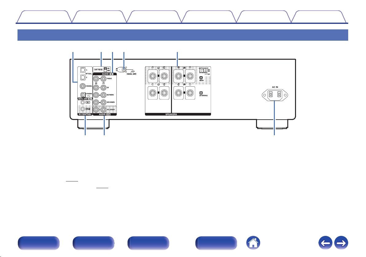
0Equipped with a USB-DAC function to support playback of high-
resolution sound sources
This unit supports the playback of high resolution audio formats such as
DSD (2.8/5.6/11.2 MHz) and PCM files up to 384 kHz/32 bits. It
provides high quality playback of high resolution files into this unit from a
computer via USB-B connection.
0DIGITAL AUDIO IN connectors (COAXIAL/OPTICAL)
You can play back PCM signals up to 192 kHz/24 bits by inputting digital
audio signals from an external device into this unit.
0Phono Equalizer
Even a user who is particular about analog records is satisfied because
the Phono Equalizer circuit for the FET input supports MM/MC.
Contents Connections Playback Settings Tips Appendix
6
Front panel Rear panel
Remote control
unit
Index
Part names and functions
Front panel
.
ru Q0eqw yo
ti
Q3 Q4Q2Q1
APower operation button (X)
This turns the power on/off. (v p. 27)
BPower indicator
This is lit as follows according to the power status:
0Power on : Green
0Standby : Off
0Power off : Off
0When the protection circuit is activated : Red (blinking)
Contents Connections Playback Settings Tips Appendix
7
Front panel Rear panel
Remote control
unit
Index
.
ru Q0e yo
ti
CRemote control sensor
This receives signals from the remote control unit. (v p. 5)
DANALOG MODE button
This switches the ANALOG MODE. (v p. 30)
EANALOG MODE indicator
This is lit as follows according to the ANALOG MODE status:
0ANALOG MODE 1/2: Green
0ANALOG MODE off: Off
FSOURCE DIRECT indicator
This is lit as follows according to the SOURCE DIRECT status:
0SOURCE DIRECT mode on: Green
0SOURCE DIRECT mode off: Off
GSOURCE DIRECT button
This turns SOURCE DIRECT mode on/off. (v p. 29)
HVOLUME knob
These adjust the volume level. (v p. 28)
IDisplay
This displays information such as the input source name, type of digital
audio signal and sampling frequency.
JInput source select knob (INPUT SELECTOR)
This selects the input source. (v p. 28)
Contents Connections Playback Settings Tips Appendix
8
Front panel Rear panel
Remote control
unit
Index
.
Q
3
Q
4
Q
2
Q
1
KHeadphones jack (PHONES)
Used to connect headphones.
Turn off speaker output when using headphones.
NOTE
0To prevent hearing loss, do not raise the volume level excessively when using
headphones.
LBASS control knob
This setting adjusts the volume level for the bass. (v p. 28)
MTREBLE control knob
This setting adjusts the volume level for the treble. (v p. 28)
NBALANCE control knob
This adjusts the balance of the volume output from the left and right
speakers. (v p. 28)
0b, c and d can be adjusted when 7 is off (SOURCE DIRECT mode is off).
Contents Connections Playback Settings Tips Appendix
9
Front panel Rear panel
Remote control
unit
Index
Rear panel
.
yui
terqw
ADIGITAL AUDIO IN connectors
Used to connect devices equipped with digital audio output connectors
and PC.
0“Connecting to a device with digital audio output
connectors” (v p. 23)
0“Connecting a PC or Mac” (v p. 24)
BCARTRIDGE selection switch
Set this switch to MM or MC according to the type of cartridge used on
your turntable.
Contents Connections Playback Settings Tips Appendix
10
Front panel Rear panel
Remote control
unit
Index
.
ter
i
yu
CAnalog audio connectors (AUDIO IN)
Used to connect devices equipped with analog audio connectors.
0“Connecting a playback device” (v p. 21)
0“Connecting a recording device” (v p. 22)
DSIGNAL GND terminal
Used to connect a turntable. (v p. 21)
ESpeaker terminals (SPEAKERS)
Used to connect speakers. (v p. 17)
FIR control input/output connectors (IR CONTROL IN/OUT)
Used to connect Denon network audio players with an IR controller.
GAUDIO OUT connectors (RECORDER)
Used to connect the input connector of a recorder. (v p. 22)
HAC inlet (AC IN)
Used to connect the power cord. (v p. 25)
Contents Connections Playback Settings Tips Appendix
11
Front panel Rear panel
Remote control
unit
Index
Remote control unit
.
w
e
r
t
y
u
q
oOperating this unit
ASignal transmitter
This transmits signals from the remote control unit. (v p. 5)
BInput source select buttons
This selects the input source. (v p. 28)
CANALOG MODE button
This switches the ANALOG MODE. (v p. 30)
DMUTE button (:)
This mutes the output audio. (v p. 28)
EPower operation button (AMP POWER X)
This turns the power on/off (standby). (v p. 27)
FVOLUME buttons (df)
These adjust the volume level. (v p. 28)
GDIMMER button
This switches the brightness of the display. (v p. 29)
Contents Connections Playback Settings Tips Appendix
12
Front panel Rear panel
Remote control
unit
Index
w
e
q
r
u
i
o
t
y
Q2
Q1
Q3
Q4
Q0
oCD player operations
A Denon CD player can be operated.
APower operation button (POWER X)
BRemote mode select button (REMOTE MODE CD)
CSystem buttons
0Skip buttons (8 / 9)
0Play/pause button (1 / 3)
0Fast-reverse/Fast-forward buttons (6 / 7)
0Stop button (n)
DInformation button (INFO)
ECursor buttons (uio p)
FCD PROGRAM button
GNumber buttons (0 – 9, +10)
HRANDOM button
IREPEAT button
JENTER button
KCD PURE DIRECT button
LCLEAR button
MDIMMER button
NMODE button
0The remote control may not operate some products.
Contents Connections Playback Settings Tips Appendix
13
Front panel Rear panel
Remote control
unit
Index
o
Q0
Q1
u
w
e
q
t
y
r
i
oNetwork audio player operations
To operate a Denon network audio player, press the REMOTE MODE
NET button to switch the remote control to the network audio player
operation mode.
APower operation button (POWER X)
BRemote mode select button (REMOTE MODE NET)
CSystem buttons
0Skip buttons (8 / 9)
0Play/pause button (1 / 3)
0Fast-reverse/Fast-forward buttons (6 / 7)
0Stop button (n)
DInformation button (INFO)
ESOURCE button
FNET FAVORITES CALL button
GCursor buttons (uio p)
HNET SRCH button
INumber buttons (0 – 9, +10)
JRANDOM button
KREPEAT button
Contents Connections Playback Settings Tips Appendix
14
Front panel Rear panel
Remote control
unit
Index
Q2
Q4
Q5
Q6
Q7
Q3
LNET FAVORITES ADD button
MENTER button
NNET SETUP button
OCLEAR button
PDIMMER button
QMODE button
0The amp can be operated with the amp operation buttons even when the remote
control mode is “NET”.
0When using it, also refer to the operating instructions of the other devices.
0The remote control may not operate some products.
Contents Connections Playback Settings Tips Appendix
15
Front panel Rear panel
Remote control
unit
Index
oContents
Connecting speakers 17
Connecting a playback device 21
Connecting a recording device 22
Connecting to a device with digital audio output connectors 23
Connecting a PC or Mac 24
Connecting the power cord 25
NOTE
0Do not plug in the power cord until all connections have been completed.
0Do not bundle power cords together with connection cables. Doing so can result in
humming or noise.
oCables used for connections
Provide necessary cables according to the devices you want to
connect.
Speaker cable
.
Audio cable
.
R
L
R
L
Optical cable
.
Coaxial digital cable
.
USB cable
.
Contents Connections Playback Settings Tips Appendix
Connections
16
Front panel Rear panel
Remote control
unit
Index
Connecting speakers
NOTE
0Disconnect this unit’s power plug from the power outlet before connecting the
speakers.
0Connect so that the speaker cable core wires do not protrude from the speaker
terminal. The protection circuit may be activated if the core wires touch the rear
panel or if the + and - sides touch each other. (“Protection circuit” (v p. 52))
0Never touch the speaker terminals while the power cord is connected. Doing so
could result in electric shock.
0Use speakers with impedances within the ranges shown below to suit how they
are used.
Speaker terminals
used on this unit
No. of connected
speakers
Speaker
Impedance
SPEAKERS A
(Standard
connection)
2 (one set) 4 – 16 Ω/ohms
SPEAKERS B 2 (one set) 4 – 16 Ω/ohms
SPEAKERS A and
SPEAKERS B 4 (two sets) 8 – 16 Ω/ohms
SPEAKERS A and
SPEAKERS B
(Bi-wiring
connection)
2 (one set) 4 – 16 Ω/ohms
oConnecting the speaker cables
Carefully check the left (L) and right (R) channels and + (red) and – (black)
polarities on the speakers being connected to this unit, and be sure to
connect the channels and polarities correctly.
1
Peel off about 10 mm of sheathing from the tip of the speaker
cable, then either twist the core wire tightly or terminate it.
.
2
Turn the speaker terminal counterclockwise to loosen it.
.
3Insert the speaker cable’s core wire to all the way into
the speaker terminal.
.
Contents Connections Playback Settings Tips Appendix
17
Front panel Rear panel
Remote control
unit
Index
4Turn the speaker terminal clockwise to tighten it.
.
Speaker terminal dimensions
.
8mm
5mm
Contents Connections Playback Settings Tips Appendix
18
Front panel Rear panel
Remote control
unit
Index
Speaker connection
This unit is equipped with two sets of speaker terminals (SPEAKER A and SPEAKER B). One set of speakers can be connected to each set of terminals,
and a total of two sets of speakers can be connected.
The same signal is output from the SPEAKERS A and SPEAKERS B terminals.
When only one set of speakers is to be connected, use either the SPEAKERS A or SPEAKERS B terminals.
.
wqwq
(R)(L)
wqwq
(R)(L)
SPEAKERS A SPEAKERS B
Contents Connections Playback Settings Tips Appendix
19
Front panel Rear panel
Remote control
unit
Index
Bi-wiring connection
This connection limits the effects of signal interference between the high range speakers (tweeters) and low range speakers (woofers), allowing you to
enjoy high quality playback.
When bi-wiring with bi-wireable speakers, connect the mid and high range terminals to SPEAKERS A (or SPEAKERS B), the low range terminals to
SPEAKERS B (or SPEAKERS A).
.
wq
wq
HIGH
LOW
wq
wq
HIGH
LOW
Speaker
(R)
Speaker
(L)
Remove shorting bar Remove shorting bar Remove shorting barRemove shorting bar
Contents Connections Playback Settings Tips Appendix
20
Front panel Rear panel
Remote control
unit
Index

Other manuals for PMA-1600NE

4

Other Denon Amplifier manuals

Denon PMA-60SP User manual

Denon

Denon PMA-60SP User manual

Denon AVC-A1HD User manual

Denon

Denon AVC-A1HD User manual

Denon POA-5200 User manual

Denon

Denon POA-5200 User manual

Denon AVC-3030 User manual

Denon

Denon AVC-3030 User manual

Denon AVP-A1HDE User manual

Denon

Denon AVP-A1HDE User manual

Denon PMA-900HNE User manual

Denon

Denon PMA-900HNE User manual

Denon AVC-A1XVA User manual

Denon

Denon AVC-A1XVA User manual

Denon PMA-1055R User manual

Denon

Denon PMA-1055R User manual

Denon AVC-X6700H User manual

Denon

Denon AVC-X6700H User manual

Denon PMA-850 User manual

Denon

Denon PMA-850 User manual

Denon DN-508A User manual

Denon

Denon DN-508A User manual

Denon AVC-X3700H User manual

Denon

Denon AVC-X3700H User manual

Denon PMA-710AE User manual

Denon

Denon PMA-710AE User manual

Denon PMA-1500AE User manual

Denon

Denon PMA-1500AE User manual

Denon HEOS Amp HS2 User manual

Denon

Denon HEOS Amp HS2 User manual

Denon AVC-A11SR Assembly instructions

Denon

Denon AVC-A11SR Assembly instructions

Denon AVP-A1HD User manual

Denon

Denon AVP-A1HD User manual

Denon 3012CI - Power Amplifier User manual

Denon

Denon 3012CI - Power Amplifier User manual

Denon AVP-A1HD User manual

Denon

Denon AVP-A1HD User manual

Denon PMA-717 User manual

Denon

Denon PMA-717 User manual

Denon POA-F100 User manual

Denon

Denon POA-F100 User manual

Denon PMA-2000IVR User manual

Denon

Denon PMA-2000IVR User manual

Denon PMA-60 User manual

Denon

Denon PMA-60 User manual

Denon PMA-60 User manual

Denon

Denon PMA-60 User manual

Popular Amplifier manuals by other brands

Onkyo TX-SV515PRO II instruction manual

Onkyo

Onkyo TX-SV515PRO II instruction manual

Yamaha PC1002 operating manual

Yamaha

Yamaha PC1002 operating manual

moon 870A owner's manual

moon

moon 870A owner's manual

Clearaudio smart phono V2 user manual

Clearaudio

Clearaudio smart phono V2 user manual

Bryston C Series 875HT owner's manual

Bryston

Bryston C Series 875HT owner's manual

evertz exponent 500ADA-EQ-L manual

evertz

evertz exponent 500ADA-EQ-L manual

Bryston 3BE Schematic diagram

Bryston

Bryston 3BE Schematic diagram

ELECRAFT KPA500 Assembly instructions

ELECRAFT

ELECRAFT KPA500 Assembly instructions

Rotel RMA-80 owner's manual

Rotel

Rotel RMA-80 owner's manual

Teac A-R650 owner's manual

Teac

Teac A-R650 owner's manual

Clarity EHA40 instruction manual

Clarity

Clarity EHA40 instruction manual

MODEL SOUNDS MSMAK66 manual

MODEL SOUNDS

MODEL SOUNDS MSMAK66 manual

Boulder 2120 instruction manual

Boulder

Boulder 2120 instruction manual

Jensen Mono Amp JPA1150M Installation & operation manual

Jensen

Jensen Mono Amp JPA1150M Installation & operation manual

Fender RUMBLE 800 COMBO owner's manual

Fender

Fender RUMBLE 800 COMBO owner's manual

Audio Control Rialto 400 quick start guide

Audio Control

Audio Control Rialto 400 quick start guide

Trivum RA410v2 Quick installation guide

Trivum

Trivum RA410v2 Quick installation guide

Cary Audio Design SLI-80 owner's manual

Cary Audio Design

Cary Audio Design SLI-80 owner's manual

manuals.online logo
manuals.online logoBrands
  • About & Mission
  • Contact us
  • Privacy Policy
  • Terms and Conditions

Copyright 2025 Manuals.Online. All Rights Reserved.