Denon DMD-M31 User manual

MINIDISC RECORDER
DMD-M31
1
18Tr02m 46s
-60 -40 -30 -20 -12 -6 -2 0
L
dB
R
PUSH
ENTER
MINIDISC RECORDER DMD-M31
89
POWER LOADING MECHANISM
MULTI REC
CD SRS
MEMORY REC
CHARACTER/
TIME/INPUT
EDIT
ON / STANDBY
OPERATING INSTRUCTIONS

2
NOTE ON USE
• Avoid high temperatures.
Allow for sufficient heat
dispersion when installed on a
rack.
• Keep the set free from moisture,
water, and dust.
• Do not let foreign objects in the
set.
• Handle the power cord carefully.
Hold the plug when unplugging
the cord.
• Unplug the power cord when not
using the set for long periods of
time.
• Do not let insecticides, benzene,
and thinner come in contact with
the set.
• Never disassemble or modify the
set in any way.
• Do not obstruct the ventilation
holes.
* (For sets with ventilation holes)
• DECLARATION OF CONFORMITY
We declare under our sole responsibility that
this product, to which this declaration relates, is
in conformity with the following standards:
EN60065, EN55013, EN55020, EN61000-3-2
and EN61000-3-3.
Following the provisions of 73/23/EEC,
89/336/EEC and 93/68/EEC Directive.
CAUTION
RISK OF ELECTRIC SHOCK
DO NOT OPEN
CAUTION:
TO REDUCE THE RISK OF ELECTRIC SHOCK,
DO NOT REMOVE COVER (OR BACK). NO
USER SERVICEABLE PARTS INSIDE. REFER
SERVICING TO QUALIFIED SERVICE PERSONNEL.
The lightning flash with arrowhead
symbol, within an equilateral triangle, is
intended to alert the user to the presence
of uninsulated “dangerous voltage”
within the product’s enclosure that may
be of sufficient magnitude to constitute a
risk of electric shock to persons.
The exclamation point within an equilateral
triangle is intended to alert the user to the
presence of important operating and
maintenance (servicing) instructions in the
literature accompanying the appliance.
WARNING:
TO PREVENT FIRE OR SHOCK HAZARD, DO
NOT EXPOSE THIS APPLIANCE TO RAIN
OR MOISTURE.
CLASS 1 LASER PRODUCT
,
CLASS 1
LASER PRODUCT,
,,
• The ventilation should not be impeded by covering the ventilation openings with items, such as newspapers,
table-cloths, curtains, etc.
• No naked flame sources, such as lighted candles, should be placed on the apparatus.
• Please be care the environmental aspects of battery disposal.
• The apparatus shall not be exposed to dripping or splashing for use.
• No objects filled with liquids, such as vases, shall be placed on the apparatus.

3
1
18Tr02m 46s
-60 -40 -30 -20 -12 -6 -2 0
L
dB
R
PUSH
ENTER
MINIDISC RECORDER DMD-M31
89
POWER LOADING MECHANISM
MULTI REC
CD SRS
MEMORY REC
CHARACTER/
TIME/INPUT
EDIT
ON / STANDBY
qwertyu
i
o
!0!1
!2!3
!8!7!6 !9 @0
!4 !5 !4 !5
FRONT PANEL
REAR PANEL
DISPLAY
q
we
rr

4
ENGLISH
IMPORTANT TO SAFETY
WARNING:
TO PREVENT FIRE OR SHOCK HAZARD, DO NOT
EXPOSE THIS APPLIANCE TO RAIN OR MOISTURE.
CAUTION:
1. Handle the power supply cord carefully
Do not damage or deform the power supply cord. If it
is damaged or deformed, it may cause electric shock
or malfunction when used. When removing from wall
outlet, be sure to remove by holding the plug attachment
and not by pulling the cord.
2. Do not open the top cover
In order to prevent electric shock, do not open the top
cover.
If problems occur, contact your DENON dealer.
3. Do not place anything inside
Do not place metal objects or spill liquid inside the
MiniDisc recorder.
Electric shock or malfunction may result.
Please, record and retain the Model name and serial number
of your set shown on the rating label.
Model No. DMD-M31 Serial No.
NOTE:
This MiniDisc recorder uses the semiconductor laser. To
allow you to enjoy music at a stable operation, it is
recommended to use this in a room of 10°C (50°F) ~ 35°C
(95°F).
Place of installation
To ensure sufficient ventilation, leave a space of at least
10 cm between the front, sides and back of the unit and
walls or other objects which may obstruct ventilation.
CAUTION:
USE OF CONTROLS OR ADJUSTMENTS OR REFORMANCE
OF PROCEDURES OTHER THAN THOSE SPECIFIED
HEREIN MAY RESULT IN HAZARDOUS RADIATION
EXPOSURE.
THE MINIDISC RECORDER SHOULD NOT BE ADJUSTED
OR REPAIRED BY ANYONE EXCEPT PROPERLY QUALIFIED
SERVICE PERSONNEL.
1
18Tr02m 46s
-60 -40 -30 -20 -12 -6 -2 0
L
dB
R
PUSH
ENTER
MINIDISC RECORDER DMD-M31
89
POWER LOADING MECHANISM
MULTI REC
CD SRS
MEMORY REC
CHARACTER/
TIME/INPUT
EDIT
ON / STANDBY
For heat dispersal, leave at least 10 cm of space
between the top, back and sides of this unit and the
wall or other components.
✽ 10 cm or more 5 cm
✽✽
✽✽
TABLE OF CONTENTS
zFeatures .................................................................... 4
xCautions on Handling ................................................ 4
cConnections .............................................................. 5
vPart Names and Functions.................................... 6, 7
bRemote Control Unit ............................................. 7, 8
nAbout MiniDiscs........................................................ 9
mNormal Playback ....................................................... 9
,Various Playback Functions .............................. 10~13
.Recording ......................................................... 13~15
⁄0 Various Recording Functions............................. 15, 16
⁄1 Long recording (MDLP recording)..................... 16, 17
⁄2 Group Functions ............................................... 17~20
⁄3 Editing............................................................... 21~27
⁄4 PICK REC Function ........................................... 27, 28
⁄5 System Functions ............................................. 28, 29
⁄6 Messages ............................................................... 30
⁄7 System Limitations ................................................. 30
⁄8 Troubleshooting....................................................... 31
⁄9 Main Specifications................................................. 31
qRCA pin plug cord ................................................. 2
wSystem connector cable........................................ 1
eOptical cable.......................................................... 1
rOperating instructions........................................... 1
tService station list................................................. 1
q w e
2ACCESSORIES
Check that the following parts are included in the
package aside from the main unit:
Thank you for purchasing this DENON MiniDisc recorder.
Please read the operating instructions thoroughly in order
to acquaint yourself with the MiniDisc recorder and
achieve maximum satisfaction from it.
1FEATURES
This unit is an audio device using the MiniDisc format.
Recording is possible for up to 80 minutes. Up to 320
minutes can be recorded by using the MDLP mode.
Operation is the same as with regular compact discs
(CDs).
1. Clear sound quality
Digital recording provides clear playback sound.
2. Abundant playback functions
Programmed playback, random playback, all track
repeat, single track repeat, etc.
3. Numerous editing functions
Editing functions for dividing, combining and moving
tracks make it possible to freely manipulate recorded
discs, and disc and track titles can be added. These
functions make it easy to create original discs.
4. Sampling rate converter
Sources with different sampling frequencies, such as
DATs and satellite broadcasts (32 kHz and 48 kHz), can
be recorded digitally.
5. Convenient system functions
This unit is equipped for system functions allowing
easy synchronized recording, timer recording/playback
and auto function and auto power on operations when
used in combination with the D-M31 series. In
addition, system units can be operated using the
system remote control unit included with the CD
receiver (UD-M31/M51).
6. MDLP (MD-Long Play) compatibility
This unit is compatible with the MDLP format, thereby
allowing stereo recording/playback for double or
quadruple the normal recording/playback time.
7. Low standby power consumption
The power consumption when the power is in the
standby mode is reduced to 1 W or less.
Installation
Do not place a TV set (even a small one) or other object
on top of this unit.
When receiving FM, AM and TV broadcasts
If this unit’s power is turned on while receiving FM, AM or
TV broadcasts, there may be noise in the sound or stripes
on the TV picture. Keep this unit’s power turned off when
not using it.
This unit uses digital technology, if an FM tuner is placed
nearby, it may cause adverse effects, such as noise in the
tuner’s antenna cable, etc.
Be sure to use coaxial cables to connect the antenna and
the tuner’s antenna terminal.
When not using this unit
2Under normal circumstances
• Always remove the disc and turn the power off.
• When leaving home for long periods of times such
as for trips, be sure to unplug the power supply cord.
2When moving this unit
• Do not subject this unit to
shocks.
• Always check that the disc has
been removed and the
connection cords disconnected
before moving this unit.
2
CAUTIONS ON HANDLING
NOTE:
• The power consumption will be less than 1 W in
standby only when connected with the D-M31
series.

(option)
5
3CONNECTIONS
NOTES:
• Do not plug power supply cords into power outlets
until all connections have been completed.
• Check the left and right channels and be sure to
interconnect them correctly (L to L, R to R).
• Plug in the power supply cords securely. Incomplete
connections will result in noise.
• Clasping the power supply cords and connection
cords together may result in humming or noise.
• After unplugging the power supply cord, wait at
least 5 seconds before plugging it back in.
Recommended System Installation
• To ensure performance and stability, install the D-M31
series as shown below.
• Do not place another component directly on top of the
CD receiver (UD-M31/M51).
• For stability, do not stack more than three components
on top of each other.
1
2
3
4
5
Connect the DMD-M31‘s SYSTEM CONNECTOR
jack (1 or 2) to the SYSTEM CONNECTOR jack of
one of the other components using the included
system cord.
Connect the DMD-M31’s DIGITAL OPTICAL IN
jack (1 or 2) to the DIGITAL OPTICAL OUT jack of
the CD receiver using optical connection cord.
Plug the power supply cord into a CD receiver’s
AC outlet or cassette deck’s AC outlet.
Connect the DMD-M31‘s LINE1 OUT jacks to the
CD receiver’s LINE1 IN jacks using the included
stereo audio cord.
Connect the DMD-M31‘s LINE1 IN jacks to the CD
receiver’s LINE1 OUT jacks using the included
stereo audio cord.
✽The DMD-M31 can also be used when connected to
a receiver other than the one in D-M31 series. In this
case, none of the system functions (auto power on,
etc.) will work.
(option)
Connecting to the D-M31 Series
2When connecting to a receiver other than the one in
the D-M31, there is no need to make connection 3.
Note that in this case none of the system functions
(auto power on, etc.) will work.
• System operations such as the auto power on function
can only be used if stereo audio cords and system cords
are connected between all the system components. Be
sure to securely connect all the connection cords
between all the units.
• Disconnecting a system cord during system operation
may result in malfunction. Be sure to unplug the power
supply cords before changing the connections.
• Install the components in such a way that the
ventilation holes of the CD receiver (UD-M31/M51) are
not obstructed.
•Use the AC OUTLET for audio equipment only. Do
not use them for hair driers, etc.
12
3
5
FM antenna
AM loop antenna
RightSubwoofer Left
Speaker systems
Power plug
AC 230 V 50 Hz
(Plug into a power outlet)
Cassette deck
(DRR-M31)
Power supply cord
(for U.K. model)
CD receiver (UD-M31/M51)
MD recorder (DMD-M31)
1
18Tr02m 46s
-60 -40 -30 -20 -12 -6 -2 0
L
dB
R
1
18Tr02m 46s
-60 -40 -30 -20 -12 -6 -2 0
L
dB
R
UD-M31/M51 DRR-M31
DMD-M31
UD-M31/M51
DMD-M31
DRR-M31
Install the sets as shown in one of these
diagrams. In either case, be sure that the
CD receiver’s ventilation holes are not
obstructed.
Side by side installation
Stacking installation
4
✽The illustration of the CD receiver in the diagram or the
operation description is for the UD-M31.

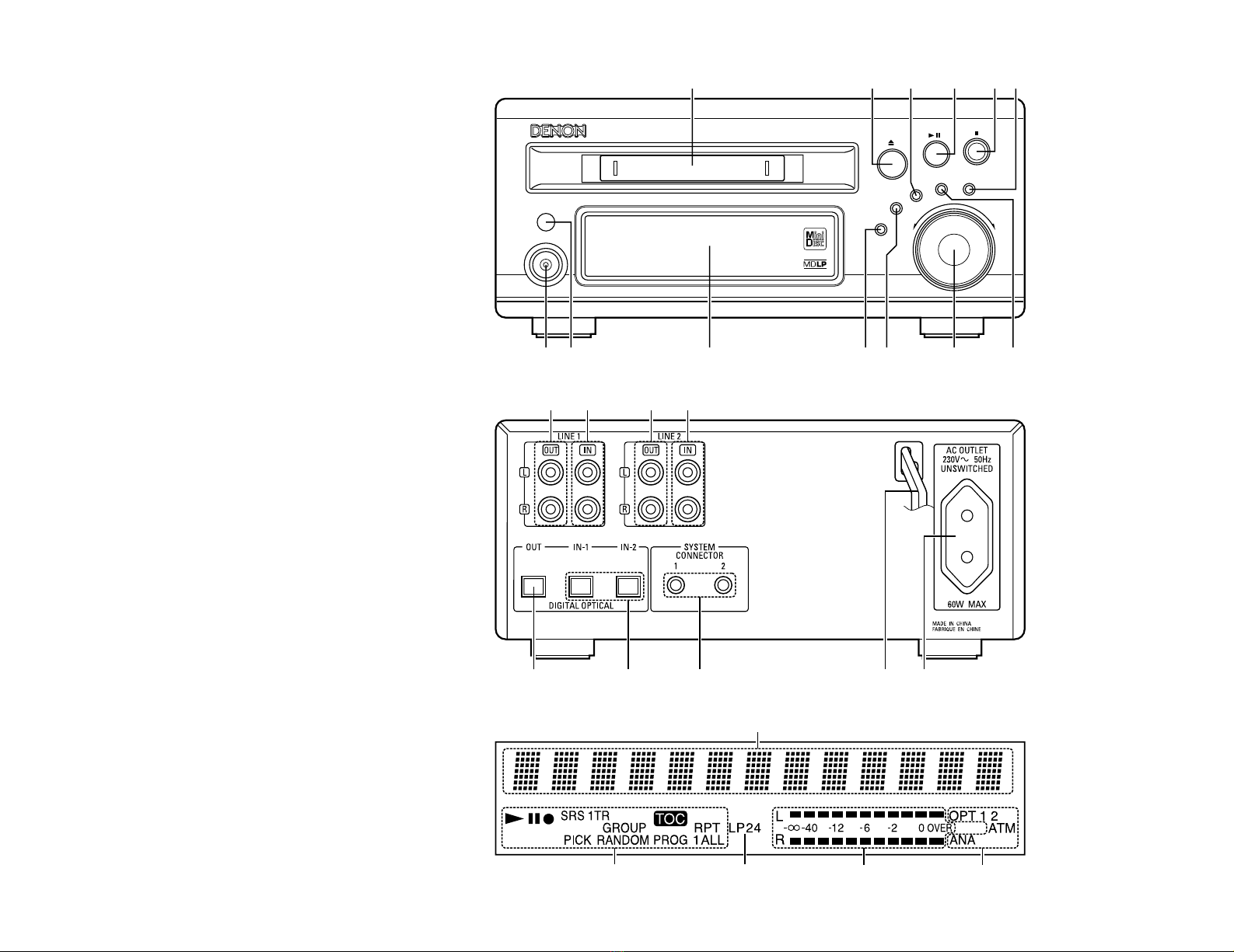
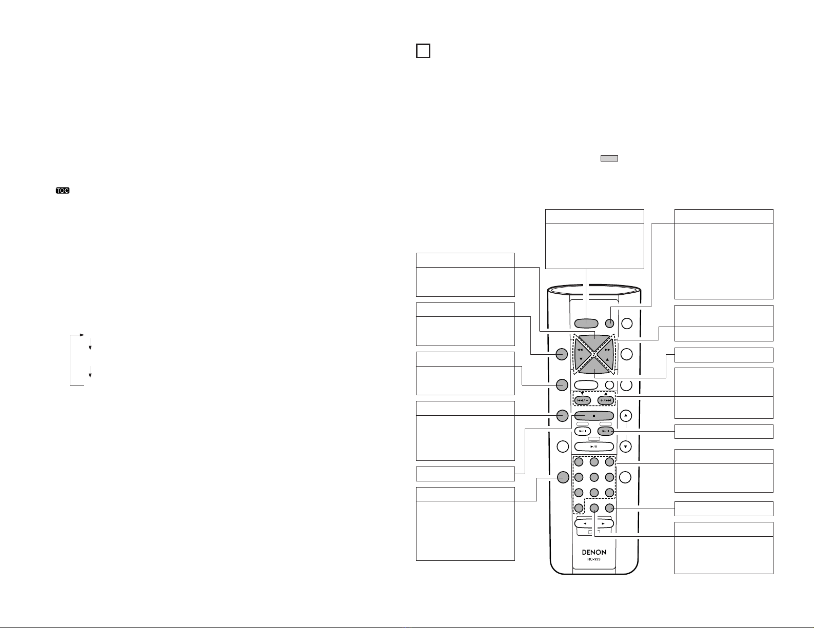
qPower operation switch (ON/STANDBY)
•Press this button once to turn the MD recorder’s
power on, then press again to set the MD recorder
to the standby mode.
The LED color changes as follows, according to the
condition:
During power ON: green
During STANDBY: red
•A press of this button after editing has been
performed results in the writing of the TOC.
wRemote sensor
•Point the separately sold remote control unit (RC-
282) at this sensor when operating it.
•When the DMD-M31 is connected in a system
with the D-M31 series, the remote control signals
are received by the remote sensor on the CD
receiver (UD-M31/M51).
eDisplay
•See page 7.
rMULTI REC button
•Press this button to record.
•The recording mode switches in the following
order each time this button is pressed:
•Press the 13button in the various recording pause
modes to start recording.
tSynchronized Recording System button
(CD SRS)
•Use this button for synchronized recording of CDs.
(See page 29.)
yJog dial/ENTER button
(89/PUSH ENTER)
•Use this dial to find the beginning of tracks and for
editing.
•Use this dial to input letters when giving titles to
tracks on the disc.
•Turning the control in the record pause mode or
during recording allows selection of the recording
level (i.e., volume) of the input signal. (See pages
11, 13 to 14.)
•Press the dial to enter editing settings.
uCharacter/Memory recording button
(CHARACTER/MEMORY REC)
•Use this button when inputting titles to switch
between capital letters, small letters and special
letters.
•A press of this button in the record pause mode
performs memory recording. (See page 16.)
iEDIT button
•This button is used when inputting disc and track
titles and for such editing operations as erasing,
dividing, combining and moving tracks.
•Press this to set the long recording mode (MDLP
recording).
•Press to conduct group editing.
o2(Stop) button
•Press this button to stop playback or recording.
•Press this button to clear the editing operation.
•A press of this button after recording or editing has
been performed results in the writing of the TOC.
!0 13(Play/Pause) button
•Press this button to start playback or recording.
•Press this button to stop playback or recording
temporarily.
!1 TIME/INPUT button
•Press this to switch the time display between the
elapsed time and the remaining time per track.
•When pressed in the stop mode, the time display
switches between the total playing time and the
recordable time.
•Use this to select the input source.
•Press and hold this button for 2 seconds or longer
in the stop condition to set the input source
selection mode.
•The input mode switches in the following order
each time this button is pressed.
✽The input source cannot be switched during
recording.
✽Opt-1:THROUGH is used when a CD recorder or
other equipment is connected to the D-M31 series.
Please see “SETTING UP THE UNIT”in the user's
manual of the CD receiver (UD-M31/M51) for details.
!2 5(Eject) button
•Press this to eject the disc.
•When editing has been performed, the TOC will be
written at the same time the disc is ejected.
!3 Disc insertion slot
•When a disc is inserted here, it is automatically
drawn into the set.
✽Be sure to insert the disc in the proper direction.
6
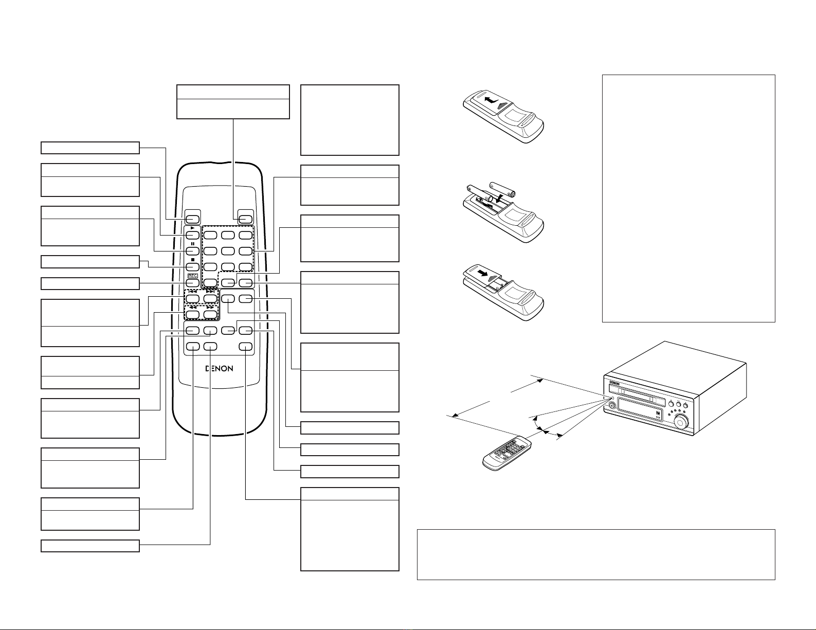
4PART NAMES AND FUNCTIONS
(1) Front Panel
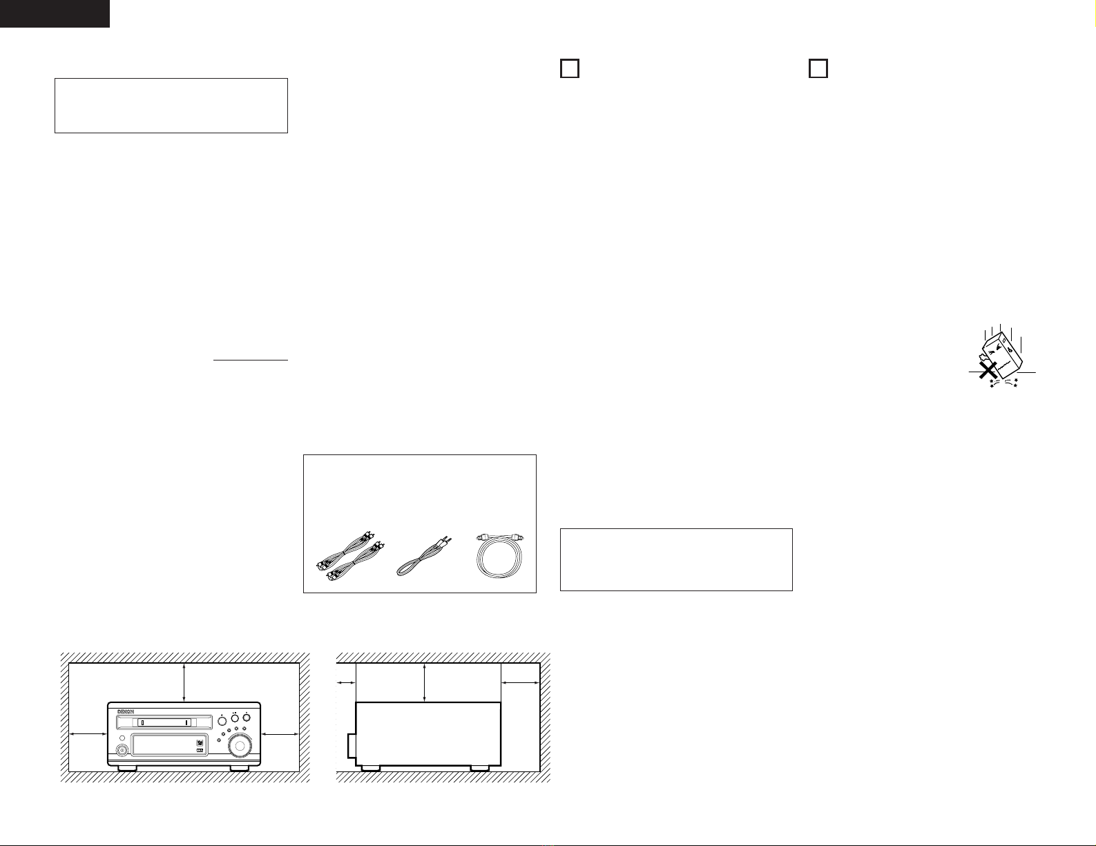
2Note on ejecting discs
•After pressing the 5(eject) button do not push
the disc back in while it is being ejected. To
reinsert the disc, wait until it comes fully out
and stops, then press it back in.
(2) Rear Panel
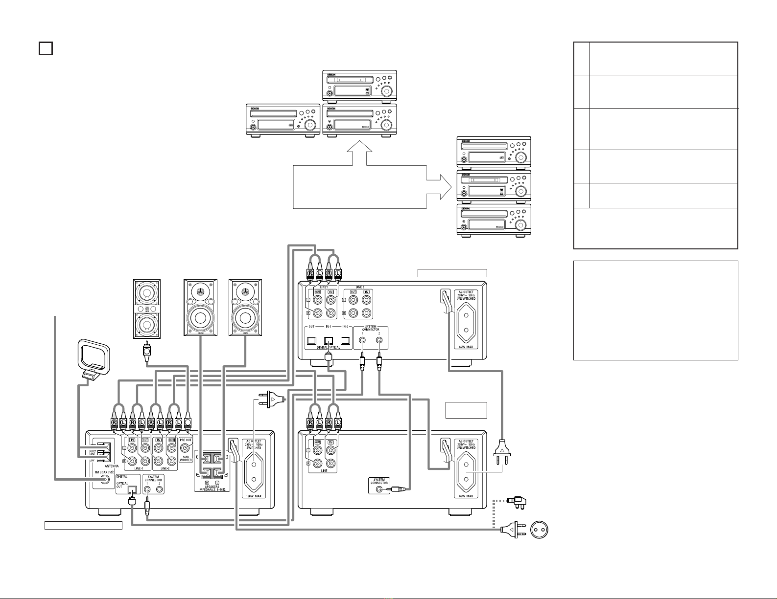
!4 LINE OUT (analog output) jacks
•When these jacks are connected to the LINE IN jacks
on the tuner-amplifier or the CD receiver, the sound
from this unit can be heard through the speakers
connected to them.
•Connect as follows to use in combination with the
D-M31 series:
•LINE1: Connect to LINE1 (or 2) IN jacks on CD
receiver (UD-M31/M51).
•LINE2: When a CD recorder or other equipment
is also going to be connected to the D-
M31 Series, connect this to the LINE IN
jack of the CD recorder or other
equipment. Please see “SETTING UP
THE UNIT”in the user's manual of the
CD receiver (UD-M31/M51) for details.
!5 LINE IN (analog input) jacks
•When these jacks connected to the LINE OUT
jacks on the tuner-amplifier or the CD receiver, the
sound of other components connected to them can
be recorded on this unit. To do so, set the TIME/
INPUT button to the “LINE 1 or 2”position.
•Connect as follows to use in combination with the
D-M31 series:
•LINE1: Connect to LINE1 (or 2) OUT jacks on CD
receiver (UD-M31/M51).
•LINE2: When a CD recorder or other equipment
is also going to be connected to the D-
M31 Series, connect this to the LINE
OUT jack of the CD recorder or other
equipment. Please see “SETTING UP
THE UNIT”in the user's manual of the
CD receiver (UD-M31/M51) for details.
!6 DIGITAL OPTICAL OUT (digital output)
jack
•Digital data is output from this jack in the form of
optical signals.
•When this jack is connected to the digital input
(OPTICAL) jack on a digital processor or D/A unit,
the sound from this unit can be heard over the
speakers.
✽When a CD recorder or other equipment is also
going to be connected to the D-M31 Series,
connect this to the DIGITAL OPTICAL IN jack of the
CD recorder or other equipment.
•Use the included optical connection cord or a
commercially available square optical connection
cord for digital audio equipment for connections to
the digital input/output jacks.
•For details on the optical fiber cord used for
connection, contact your nearest DENON Dealer.
NOTES:
•When the power supply cord is unplugged from the
power outlet as well, the DMD-M31’s backup
function is activated and the recorded table of
contents (TOC) data is stored in the memory. The
data is only backed up for 2 to 3 days, so after
recording, either eject the disc immediately or press
the power button to set the power to the standby
mode. (In this way the TOC is written on the disc
immediately.)
•The backup function is not activated for edited table
of contents (TOC) data, so be sure to form the
following operation after editing:
1. Press the 2(stop) button to record the TOC.
2. Eject the disc.
3. Press the power button to set the power to the
standby mode.
•If the backup function turns off before the TOC data
is written, the contents of the recording or editing
operation are cleared and cannot be retrieved. (See
page 9.)
Normal recording pause mode
PICK REC recording pause mode
!7 DIGITAL OPTICAL IN (digital input) jacks
•Use this jack to input digital data.
•When connected to the optical digital output jack of
a CD player, DAT deck, satellite broadcast tuner or
another MD recorder, the sound from that unit can
be recorded digitally on this unit. Set the TIME/
INPUT button to “Opt 1”when the IN1 jack is
connected, “Opt 2”when the IN2 jack is connected.
✽Connect as follows to use in combination with the
D-M31 series:
•IN-1: Connect to the digital output terminal
(DIGITAL OPTICAL OUT) on CD receiver
(UD-M31/M51).
•Use the included optical connection cord or a
commercially available square optical connection
cord for digital audio equipment for connections to
the digital input/output jacks.
•For details on the optical fiber cord used for
connection, contact your nearest DENON Dealer.
!8 SYSTEM CONNECTOR (1 and 2)
•When using this unit in combination with the D-
M31 series, connect this terminal to the system
connector terminal on another unit using the
included system connector cable.
!9 Power supply cord
•Plug this cord into a wall power outlet or AC outlet
of UD-M31/M51 or DRR-M31.
•When using in combination with the D-M31 series,
connect to the AC outlet on the CD receiver (UD-
M31/M51) or one of the other components in the
D-M31 series.
@0 AC OUTLET
•Use this when using this unit with the M31 series.
For connections, refer to “CONNECTIONS”. (60 W
MAX.)
Opt-1: MD Opt-1: THROUGH Opt-2
LINE 1LINE 2

7
qMulti display
•The number of tracks, track number, playing time,
title, current operation and various messages are
displayed here.
wMode indicators
1: Lights in the play mode.
Flashes during the manual search operation in
the play mode.
3: Lights in the pause mode.
Flashes during the manual search operation in
the pause mode.
4: Lights in the recording and recording pause modes.
SRS/SRS 1TR:
Lights in the CD synchronized recording mode.
:
Lights when the contents of the MiniDisc are being
changed after the recording, erasing, title input or
another editing operation has been performed.
GROUP:
Lights in the group function mode.
PICK:
Lights in the PICK REC recording mode.
RANDOM:
Lights in the random play mode.
PROG:
Lights during the program setting and program
play modes.
RPT:
Lights as follows each time the REPEAT button is
pressed.
eLevel meter
•Indicates the playing level in the play mode, the
recording level in the recording mode.
rMode indicators
OPT 1 (or OPT 2):
Lights when the DIGITAL OPTICAL IN 1 (or 2) jack
is selected.
✽Normal recording is not possible if this indicator
is flashing during the recording operation. Check
the connections to the digital input jacks.
✽When “Opt-1: THROUGH”is selected by the
input source selection of this unit (i.e., when a
CD recorder or other equipment has also been
connected to the D-M31 series), only the
“OPT”display lights.
ANA 1 (or ANA 2):
Lights when the LINE 1 (or 2) IN jacks are selected.
ATM:
Lights when ATM on is set during analog recording.
Also lights during digital recording.
LP2:
Lights when the LP2 recording mode (double the
recording time of the normal recording mode) is
selected during MDLP recording.
LP4:
Lights when the LP4 recording mode (quadruple
the recording time of the normal recording mode)
is selected during MDLP recording.
Off : Normal playback
RPT : 1-track repeat playback
1
RPT : All-track repeat playback
ALL
(3) Display
✽
5REMOTE CONTROL UNIT
2No remote control unit is included with this unit. When system connections are made, this unit can be
controlled with the system remote control unit (RC-933) included with the CD receiver (UD-M31/M51). When
using the CD receiver’s remote control unit to control this unit, point the remote control unit at the CD
receiver (UD-M31/M51).
2If only this unit is purchased, also purchase a separately sold remote control unit (RC-282) if you wish to
control this unit remotely.
Names and Functions of Remote Control Unit Buttons is included with the UD-M31/M51
2The MD-recorder related buttons on the system remote control unit included with the UD-M31/M51 are
explained below. Buttons shared with other models ( ) automatically function as MD recorder control
buttons thanks to the auto function utility.
Buttons marked “✽”are only for the MD recorder.
2Buttons not explained here function in the same way as the corresponding buttons on the main unit.
+1010
PANEL
CALL
DISC
SKIP
GROUP
CT
PTY
REPEAT
RDS
RANDOM
TITLE/CHARACTER TIME
EDIT
TUNING TUNING
ENTER
MEMORY
TONE/SDB
TUNER
BAND
CD-R MD
CD
123
654
987
CLEAR
TAPE
DISPLAY
VOLUME
FUNCTION
SLEEP
SYSTEM
POWER
PRESET
PROG/
DIRECT
1 to 10 (number) buttons
Use these buttons for direct
search and programmed
playback.
2(stop) button
ENTER button
CLEAR button
8and 9(automatic
search reverse and forward)
buttons
Use this to find the beginning
of a track. (See page 11.)
6
and
7
(manual search
reverse and forward) buttons
(See page 10.)
RANDOM button
Press this button to play the
track in random order.
(See page 12.)
+10 button
Use this button to enter track
numbers of 11 or over for
direct search and programmed
playback.
CALL button
Use this button to check the
programmed tracks.
During group playback,
switches between group
display mode and track
display mode.
(See pages 12, 18, 19.)
GROUP/PROG/DIRECT button
Press to switch group playback,
program setting/playback and
direct playback. Normally this
is set to the direct search mode.
(See pages 10~12, 17~20.)
TITLE/CHARACTER button
Press this button to switch the
time display to the title display.
When inputting titles to switch
between capital letters, small
letters and special letters.
EDIT button
This functions in the same way
as the EDIT button on the main
unit.
REPEAT button
Press this button to play a single
track or all tracks repeatedly.
(See pages 12, 13.)
TIME button
•Press this to switch the
time display between the
elapsed time and the
remaining time per track.
•When pressed in the stop
mode, the time display
switches between the total
playing time and the
recordable time.
1/3(play/pause) button
✽The illustration used in the operation description is the system remote control unit (RC-933) supplied with the UD-
M31.

8
EJECT
POWER
123
456
789
10 +10
CALL
REMOTE CONTROL UNIT RC-282
M
CLEAR GROUP
PROG/
DIRECT
REPEAT RANDOM EDIT ENTER
TIMETITLE
CHARACTER
Power operation switch
Press this button to switch the power
between the on and standby modes.
EJECT button
1(play) button
Press this button to start
playback or recording.
3(pause) button
Press this button to stop
playback or recording
temporarily.
2(stop) button
REC (recording) button
8and 9(automatic
search reverse and forward)
buttons
Use this to find the beginning of
a track. (See page 11.)
6and 7(manual search
reverse and forward) buttons
(See page 10.)
REPEAT button
Press this button to play a single
track or all tracks repeatedly.
(See pages 12, 13.)
RANDOM button
Press this button to play the
track in random order. (See page
12.)
TITLE button
Press this button to switch the
time display to the title display.
CHARACTER button
1 to 10 (number) buttons
Use these buttons for direct
search and programmed
playback.
+10 button
Use this button to enter track
numbers of 11 or over for direct
search and programmed
playback.
CALL button
Use this button to check the
programmed tracks.
During group playback, switches
between group display mode
and track display mode.
(See pages 12, 18, 19.)
GROUP/PROG/DIRECT
(group/program/direct)
button
Press to switch group playback,
program setting/playback and
direct playback. Normally this is
set to the direct search mode.
(See pages 10~12, 17~20.)
CLEAR button
EDIT button
ENTER button
TIME button
•Press this to switch the time
display between the elapsed
time and the remaining time
per track.
•When pressed in the stop
mode, the time display
switches between the total
playing time and the
recordable time.
Names and Functions of Remote Control Unit Buttons (The RC-282 is sold separately.)
2Use this remote control unit if you have purchased this unit separately.
2Buttons not explained here function in the same way as the corresponding buttons on the main unit.
NOTE:
•When the DMD-M31 is
connected in a system with
the D-M31 series, the DMD-
M31’s power cannot be
switched between the on and
standby modes using the
power button on the remote
control unit.
1
18Tr02m 46s
-60 -40 -30 -20 -12 -6 -2 0
L
dB
R
PUSH
ENTER
MINIDISC RECORDER DMD-M31
89
POWERLOADING MECHANISM
MULTIREC
CDSRS
MEMORYREC
CHARACTER/
TIME/INPUT
EDIT
ON / STANDBY
EJECT
POWER
123
456
789
10 +10
CALL
REMOTECONTROL UNIT RC-282
M
CLEARGROUP
PROG/
DIRECT
REPEATRANDOMEDITENTER
TIME
TITLE
CHARACTER
30˚
30˚
Approx. 7 meters
(1) Inserting the batteries
Cautions on batteries
•Use R6P (AA) batteries in the remote control unit.
•The batteries should be replaced with new ones
after approximately one year, though this depends
on the frequency with which the remote control
unit is used.
•Even if the batteries are less than a year old,
replace them with new ones if the remote control
unit no longer operates even from a short distance
from the main unit.
•The included battery is only for verifying operation.
Replace it with a new battery as soon as possible.
•When inserting new batteries, wait about two
minutes after removing the old batteries before
inserting the new ones.
•Be sure to set the batteries in the proper “<”and
“>”directions, as indicated by the marks in the
remote control unit’s battery compartment.
•Remove the batteries when not using the remote
control unit for long periods of time.
•To avoid explosions and fluid leakage:
•Do not use one new battery with one old one.
•Do not use two different types of batteries.
•Do not short-circuit, disassemble, heat or dispose
of batteries in flames.
•If the battery fluid should leak, wipe all the fluid off
the battery compartment, then insert new batteries.
qRemove the remote control unit’s back lid.
wInsert the two R6P (AA) batteries in the battery
compartment, in the direction indicated by the marks
inside the compartment.
ePut the back lid back on.
(2) Using the remote control unit
NOTES:
•The remote control unit may not operate if the
remote sensor is exposed to direct sunlight or strong
artificial light, or if there is an obstacle between it and
the remote sensor.
•Do not press buttons on the main unit and on the
remote control unit at the same time. Doing so will
result in malfunction.
2The separately sold remote control unit (RC-282) can be used to operate the DMD-M31 from a distance.
•Point the remote control unit at the remote sensor as
shown on the diagram when operating it.
•When the DMD-M31 is connected in a system with the
D-M31 series, the remote control signals for all the
system components are received at the remote sensor
of the CD receiver (UD-M31/M51).
•The remote control unit can be used from a straight
distance of about 7 meters, but this distance will be
shorter if the there is an obstacle in the way or if the
remote control unit is not pointed directly at the remote
sensor.
•Use the remote control unit within a range of 30°to the
left and right of the remote sensor.

PANEL
CALL
DISC
SKIP
GROUP
CT
PTY
REPEAT
RDS
RANDOM
EDIT
TUNING TUNING
ENTER
MEMORY
TONE/SDB
TUNER
PRESET
BAND
CD-R MD
CD
123
654
987
CLEAR
DISPLAY
VOLUME
FUNCTION
SLEEP
PROG/
DIRECT
3
4
9
2MiniDiscs are compact in size and offer a maximum
playback/recording time of 80 minutes in the normal
mode and up to 320 minutes in the MDLP mode (long-
play mode).
There are two types of MiniDiscs: those for playback
only, and those for recording and playback.
Playback only MiniDiscs
•These discs are for playback only.
Commercially available music
MDs are of this type.
•These are laser discs, like regular
compact discs.
•Tracks on such discs cannot be
edited.
Recordable MiniDiscs
•These are magneto-optical discs
on which both recording and
playback are possible.
Recording is performed through
magnetic modulation.
•Re-recording is also possible.
Accidental erasure prevention tabs
These tabs protect recordable MiniDiscs from accidental
erasure.
To avoid accidentally erasing the recording, open the tab so
that the hole is exposed. (See the diagram below.) When
this is done, “Protected”is displayed if you attempt to
record, erase or otherwise edit the disc, and the recording
is protected. To record or erase the disc, set the tab back
to its original position (with the hole covered).
6ABOUT MINIDISCS
Recording on discs
MiniDiscs include a section in which the audio signals are
recorded and a section in which such data as track
numbers and track titles are recorded.
2The TOC
With MiniDiscs, after the audio signals are recorded,
data used for checking the tracks (TOC —Table of
Contents) is also recorded on the disc. This TOC data
is used when playing the disc. In addition, editing is
performed by rewriting the TOC data.
The TOC is recorded in the following cases:
•When recording is stopped.
•When the MD is ejected.
•When the power button is pressed setting the unit to
the standby mode.
•When the 2(stop) button is pressed in the stop mode.
When TOC writing starts, the “”indicator flashes.
Do not shake the main unit or unplug the power supply
cord while the TOC is being written. If the data is not
recorded properly, it will not be possible to play the disc.
2Handling MiniDiscs
MiniDiscs are housed in cartridges, so there is no need
to worry about dirt and scratches. However, dirty or
warped cartridges may cause malfunction. Be careful
of the following to ensure long-lasting, high quality
sound:
•Do not touch the disc surface directly.
•Do not open the shutter by hand.
•Do not place MiniDiscs in dusty, dirty or humid places.
•Do not place MiniDiscs in places exposed to direct
sunlight or high temperatures.
Cleaning
Use a dry cloth to gently wipe dirt or dust off the cartridge.
Do not apply excessive force.
m
Section in which track
numbers and track titles
are recorded (TOC)
Section in which audio
signals are recorded
Hole exposed
Slide the tab
m
m
1
18Tr02m 46s
-60 -40 -30 -20 -12 -6 -2 0
L
dB
R
PUSH
ENTER
MINIDISC RECORDER DMD-M31
89
POWER LOADING MECHANISM
MULTI REC
CD SRS
MEMORY REC
CHARACTER/
TIME/INPUT
EDIT
ON / STANDBY
3 42
1
7NORMAL PLAYBACK
1. Starting playback
(Main unit) (Remote control unit)
Disc Set TOC Reading
Live
12
62m 03s
Total no. tracks Recorded time Disc title
1Turn on the power.
2
Load the disc.
•Insert the disc into the disc insertion slot in the direction indicated by the arrow on the top of the disc.
The disc is drawn in automatically.
3
Press the 1/3(play/pause) button.
•Playback begins.
•The disc title is not displayed if no disc title has been input.
Opening 01 05m 28s
•The track title is not displayed if no track title has been input.
Track title Currently playing track Track’s elapsed time
2. Stopping playback
4Press the 2(stop) button.
•Playback stops.
•The stop mode is set automatically once all the tracks on the disc have been played.
First try playing the tracks in order.

10
8VARIOUS PLAYBACK FUNCTIONS
In addition to normal playback, this unit also offers the playback functions described below.
•To operate this unit using the system remote control unit included with the CD receiver (UD-M31/M51), make system
connections between this unit and the UD-M31/M51. (Refer to page 5.)
1. Playing a certain track (remote control unit only) …………………………… Direct Search
+1010
PANEL
CALL
DISC
SKIP
GROUP
CT
PTY
REPEAT
RDS
RANDOM
TITLE/CHARACTER TIME
EDIT
TUNING TUNING
ENTER
MEMORY
TONE/SDB
TUNER
PRESET
BAND
CD-R MD
CD
123
654
987
CLEAR
TAPE
DISPLAY
VOLUME
FUNCTION
SLEEP
SYSTEM
POWER
PROG/
DIRECT
1
2
1Press the FUNCTION button and select MD.
2
Use the number buttons (1 to 10) and the +10 button to input the number of the desired track.
•For example:
Press button to listen to the 4th track, buttons and to listen to the 12th track. Playback begins
from that track.
2+104
(Remote control unit)
2. Finding the desired position while listening to the sound………………… Manual Search
•Use this function to skip rapidly through the disc while listening to the
sound.
This function comes in handy when you want to find a certain section
within a long track.
•The manual search mode is set when one of the manual search buttons
(6and 7) on the remote control unit is pressed and held in during
playback. The disc moves slowly at first, then rapidly. Normal playback
resumes when the button is released.
•The 1(play) indicator flashes when the manual search operation is
started from the play mode, and the 3(pause) indicator flashes when
the manual search operation is started from the pause mode.
PTY
REPEAT
RDS
RANDOM
TITLE/CHARACTER TIME
EDIT
TUNING TUNING
ENTER
MEMORY
TONE/SDB
TUNER
PRESET
FUNCTION
SLEEP
SYSTEM
POWER
1
2
(1) Searching forward
1
During playback, press and hold in the 7(manual
search forward) button on the remote control unit.
•Normal playback resumes from the point at which the
button is released.
•Playback stops if the end of the last track on the disc
is reached while pressing the 7(manual search
forward) button on the remote control unit.
•For high-speed forward search without hearing the
sound, press the 7(manual search forward) button
while in the pause mode.
Press and hold in the 7(manual search
forward) button on the remote control
unit.
2nd
track 3rd track 4th
track
Playback Skip Skip Skip Skip Skip
(2) Searching backward
2
During playback, press and hold in the 6(manual
search reverse) button on the remote control unit.
•Normal playback resumes from the point at which the
button is released.
•Manual search stops and playback starts if the
beginning of the first track on the disc is reached
while pressing the 6(manual search reverse)
button on the remote control unit.
•For high-speed backward search without hearing the
sound, press the 6(manual search reverse) button
while in the pause mode.
Press and hold in the 6(manual
search reverse) button on the
remote control unit.
4th
track 5th track 6th
track
Skip Skip Skip Skip Skip
NOTE:
•There may be a slight break in the sound when returning to normal playback from the manual search mode.
(remote control unit only)
(Remote control unit)

11
3. Finding the beginnings of tracks during playback ……………………… Automatic Search
(1) Moving ahead to the beginning of the next track
1
Either turn the jog dial (ENTER) on the main unit clockwise
(,) or press the 9(automatic search forward) button
on the remote control unit.
•During the search operation, turn the jog dial (ENTER)
on the main unit clockwise (,) again or press the
9(automatic search forward) button on the remote
control unit again to move further on to the beginning
of the following track.
Turn the jog dial (ENTER) on the main unit clockwise
(,) or press the 9(automatic search forward)
button on the remote control unit.
2nd track 3rd track
(2) Moving back to the beginning of the current track
1
Either turn the jog dial (ENTER) on the main unit
counterclockwise (.) or press the 8(automatic search
reverse) button on the remote control unit.
•During the search operation, turn the jog dial (ENTER)
on the main unit counterclockwise (.) again or press
the 8(automatic search reverse) button on the
remote control unit again to move further back to the
beginning of previous track.
Turn the jog dial (ENTER) on the main unit
counterclockwise (.) or press the automatic search
reverse (8) button on the remote control unit.
3rd track 4th track 5th track
4th track
DISC
SKIP
GROUP
CT
PTY
REPEAT
RDS
RANDOM
TITLE/CHARACTER TIME
EDIT
TUNING TUNING
ENTER
MEMORY
TONE/SDB
TUNER
PRESET
BAND
CD-R MD
CD
VOLUME
FUNCTION
SLEEP
SYSTEM
POWER
PROG/
DIRECT 1
PUSH
ENTER
89
MULTI REC
CD SRS
1
(Main unit) (Remote control unit)
DISC
SKIP
GROUP
CT
PTY
REPEAT
RDS
RANDOM
TITLE/CHARACTER TIME
EDIT
TUNING TUNING
ENTER
MEMORY
TONE/SDB
TUNER
PRESET
BAND
CD-R MD
CD
VOLUME
FUNCTION
SLEEP
SYSTEM
POWER
PROG/
DIRECT
1
PUSH
ENTER
89
MULTI REC
CD SRS
1
(Main unit) (Remote control unit)
4. Stopping playback temporarily …………………………………………………………… Pause
•Use this function to stop playback temporarily then resume from the same point
1
During playback, press the 1/3(play/pause) button.
•The pause mode is set.
•Press the 1/3(play/pause) button to resume playback
from the point at which the pause mode was set.
Press the 1/3(play/pause) button.
4th track 5th track 6th track
(Pause)
5. Playing tracks in a certain order ……………………………… Track Programmed Playback
•Use this function to select certain tracks from the disc and program them to play in a certain order.
•
Up to 25 tracks can be programmed.
1Press the FUNCTION button and select MD.
2In the stop mode, press the GROUP/PROG/DIRECT button and display “Track Program”.
•The “PROG”indicator lights.
3Use the number buttons and the +10 button to select the tracks for programmed playback.
•For example, to program the 3rd, 12th and 7th tracks, press , , and .
72+103
4Press the 1/3(play/pause) button.
•The tracks are played in the programmed order.
Press the 1/3(play/pause) button.
PANEL
CALL
DISC
SKIP
GROUP
CT
PTY
REPEAT
RDS
TUNING TUNING
ENTER
MEMORY
TONE/SDB
TUNER
PRESET
BAND
CD-R MD
CD
123
654
987
CLEAR
DISPLAY
VOLUME
FUNCTION
PROG/
DIRECT
1
1
18Tr02m 46s
-60 -40 -30 -20 -12 -6 -2 0
L
dB
R
PUSH
ENTER
MINIDISC RECORDER DMD-M31
89
POWER LOADING MECHANISM
MULTI REC
CD SRS
MEMORY REC
CHARACTER/
TIME/INPUT
EDIT
ON / STANDBY
1
(Main unit) (Remote control unit)
+1010
PANEL
CALL
DISC
SKIP
GROUP
CT
PTY
REPEAT
RDS
RANDOM
EDIT
TUNING TUNING
ENTER
MEMORY
TONE/SDB
TUNER
PRESET
BAND
CD-R MD
CD
123
654
987
CLEAR
TAPE
DISPLAY
VOLUME
FUNCTION
SLEEP
PROG/
DIRECT
1
3
4
2
(Remote control unit)
(remote control unit only)

12
•To check the contents of the program, press the CALL button. The programmed tracks appear in the programmed
order on the display each time the CALL button is pressed.
•To change the program, press the CALL button to display the track you want to change, press the CLEAR button,
then program the desired track.
Or press the CLEAR button while in the stop mode, then program the desire track. Each press of the CLEAR
button erases one track in order starting from the last programmed track. Pressing the numerical key pad or the
+10 button once again allows for continued programming.
•To clear the entire program, press the GROUP/PROG/DIRECT or 5(eject) button while in the stop mode.
NOTES:
•The single track repeat mode cannot be set during program playback.
•It is not possible to play a certain track (Direct Search) during program playback.
•Programs with total playing times of over 999 minutes can be set, but the time will not be displayed properly.
6. Playing in random order (remote control unit only) …………………… Random Playback
•Use this function to play all the tracks on the disc once in random order.
1Press the FUNCTION button and select MD.
2In the stop mode, press the RANDOM button.
•The “RANDOM”indicator lights.
3
Press the 1/3(play/pause) button.
•During normal playback:
Tracks are automatically played in random order.
•During the all-track repeat mode:
All the tracks are played once in random order, then repeated in another random order.
•To cancel the random play mode, either set the stop mode or press the RANDOM button again.
NOTE:
•The single track repeat mode cannot be set during random playback.
DISC
SKIP
GROUP
CT
PTY
REPEAT
RDS
RANDOM
TITLE/CHARACTER TIME
EDIT
TUNING TUNING
ENTER
MEMORY
TONE/SDB
TUNER
PRESET
BAND
CD-R MD
CD
123
VOLUME
FUNCTION
SLEEP
POWER
PROG/
DIRECT
3
1
2
1
18Tr02m 46s
-60 -40 -30 -20 -12 -6 -2 0
L
dB
R
PUSH
ENTER
MINIDISC RECORDER DMD-M31
89
POWER LOADING MECHANISM
MULTI REC
CD SRS
MEMORY REC
CHARACTER/
TIME/INPUT
EDIT
ON / STANDBY
3
(Main unit) (Remote control unit)
7. Playing repeatedly (remote control unit only) …………………………… Repeat Playback
(1) Playing a single track repeatedly [Single Track Repeat]
2Press the REPEAT button once.
•The “”indicators light on the display and the single track repeat mode is set.
RPT
1
3Either turn the jog dial (ENTER) on the main unit or use the automatic search buttons ( 8and 9) on the
remote control unit to select the track to be played repeatedly.
Press the 1/3(play/pause) button.
•Playback starts.
•Once the selected track ends, it is played again from
the beginning.
•The single track repeat mode can also be set by
pressing the REPEAT button during playback. The
current track is played repeatedly.
Press the REPEAT button once.
2nd track 3rd track 4th track
4
This operation
is repeated.
1Press the FUNCTION button and select MD.
•To cancel the single track repeat mode, press the REPEAT button repeatedly until the “RPT”indicator turns off.
DISC
SKIP
GROUP
CT
PTY
REPEAT
RDS
RANDOM
TITLE/CHARACTER TIME
EDIT
TUNING TUNING
ENTER
MEMORY
TONE/SDB
TUNER
PRESET
BAND
CD-R MD
CD
VOLUME
FUNCTION
SLEEP
SYSTEM
POWER
PROG/
DIRECT
4
1
3
2
1
18Tr02m 46s
-60 -40 -30 -20 -12 -6 -2 0
L
dB
R
PUSH
ENTER
MINIDISC RECORDER DMD-M31
89
POWER LOADING MECHANISM
MULTI REC
CD SRS
MEMORY REC
CHARACTER/
TIME/INPUT
EDIT
ON / STANDBY
4
3
(Main unit) (Remote control unit)

13
Press the REPEAT button twice.
•The “”indicators light on the display and the all track repeat mode is set.
RPT
ALL
(2) Playing all tracks repeatedly [All Track Repeat]
2
3
Press the 1/3(play/pause) button.
•The disc is played repeatedly.
•The all track repeat mode can also be set by pressing the REPEAT button twice during playback.
•If the REPEAT button is pressed during programmed playback, the tracks are played repeatedly in the
programmed order.
NOTE:
•The single track repeat mode cannot be set during programmed playback or random playback.
1Press the FUNCTION button and select MD.
•To cancel the all track repeat mode, press the REPEAT button repeatedly until the “RPT”indicator turns off.
CALL
DISC
SKIP
GROUP
CT
PTY
REPEAT
RDS
RANDOM
EDIT
TUNING TUNING
ENTER
MEMORY
TONE/SDB
TUNER
PRESET
BAND
CD-R MD
CD
123
654
DISPLAY
VOLUME
FUNCTION
SLEEP
PROG/
DIRECT
3
1
2
1
18Tr02m 46s
-60 -40 -30 -20 -12 -6 -2 0
L
dB
R
PUSH
ENTER
MINIDISC RECORDER DMD-M31
89
POWER LOADING MECHANISM
MULTI REC
CD SRS
MEMORY REC
CHARACTER/
TIME/INPUT
EDIT
ON / STANDBY
3
(Main unit) (Remote control unit)
1. Starting recording (Manual Recording)
1
2
3
4
Turn on the power.
Load the recordable MiniDisc that is to be recorded.
When using a blank disc or a no-track disc, the Auto Rec Pause function automatically sets this unit to the
recording pause mode (There is no need to perform step 7.)
•Adjust the recording level in step 8.
When using an already recorded MiniDisc, press the TIME/INPUT button on the main unit or the TIME button
on the remote control unit to check the recordable time.
•The time display switches between the total recorded time and the recordable time each time the TIME/
INPUT button on the main unit or the TIME button on the remote control unit is pressed.
Set the input mode to “LINE1”or “LINE2”by using the TIME/INPUT button.
•Please see !1 TIME/INPUT button under “vPART NAMES AND FUNCTIONS”on Page 6 for information
about how to perform input mode selection.
•The indicator for the selected input source (“ANA1”or “ANA2”) lights.
(1) Analog recording
DISC
SKIP
GROUP
CT
PTY
REPEAT
RDS
RANDOM
TITLE/CHARACTER TIME
EDIT
TUNING TUNING
ENTER
MEMORY
TONE/SDB
TUNER
PRESET
BAND
CD-R MD
CD
VOLUME
FUNCTION
SLEEP
SYSTEM
POWER
PROG/
DIRECT
9
5
3
5,8
5
1
18Tr02m 46s
-60 -40 -30 -20 -12 -6 -2 0
L
dB
R
PUSH
ENTER
MINIDISC RECORDER DMD-M31
89
POWER LOADING MECHANISM
MULTI REC
CD SRS
MEMORY REC
CHARACTER/
TIME/INPUT
EDIT
ON / STANDBY
92 3,4
8 571
(Main unit) (Remote control unit)
9RECORDING
•When recording on an already recorded disc, recording automatically starts from the end of the section last recorded.
When doing so, pay attention to the remaining time.
•To clear the entire content of the disc and record from the beginning, first erase the entire disc. (For instructions on
erasing the entire disc, refer to “Editing —(1) Erasing all tracks”on page 22.)
•To record on a disc, make sure the accidental erasure prevention tab is closed and the hole is covered.
•Use of the CD synchronized recording function (page 29) and the Synchronized recording function (page 29) will be
convenient when there is a system connection with the D-M31 Series.
•When recording without a system connection, the insertion of a blank (i.e., unrecorded) disc or a no-track disc (i.e., a
disc with only the disc name recorded) will result in the unit automatically entering the record pause mode which will
make analog recording Step 7 and digital recording Step 6 unnecessary. (The Auto Rec Pause function.)
The Auto Rec Pause function will also be activated when the power is switched on while one of these discs is in the
unit.
•When recording of the TOC is not performed after editing, “
Write UTOC
”is displayed and the unit will not enter
the recording mode.
13

14
5
Select On/Off of the Auto Track Marking function.
•ATM Function On
The “ATM”indicator will light. When a blank portion (of about 3 seconds or greater) of the recording input
signal is detected, the track number is automatically associated and recorded.
•ATM Function Off
This is recorded as the following track.
Press the EDIT button, turn the jog dial of the main unit or press the automatic search buttons (8and 9)
of the remote control unit, and select the Analog A.T.M. mode.
•“
nalog .T.M?
”is displayed.
Press the ENTER button, turn the jog dial of the main unit or press the automatic search buttons (8and
9) of the remote control unit, and select On/Off of the A.T.M. function.
•“
.T.M On(Off)
”is displayed.
Press the ENTER button.
6
7
8
9
10
Start playing the selection you want to record on the CD receiver, Cassette deck, etc.
Press the MULTI REC button.
•The recording standby mode is set.
Adjust the recording level with the jog dial.
•Adjust the input level adjustment control so that the “OVER”indicator does not light even when the volume
is loudest. After adjusting, set the source to be recorded to the standby mode.
•The set recording level will be stored in memory, but this data might be lost if the unit is not connected to a
power source for 2 to 3 days.
Press the 1/3(play/pause) button.
•Recording starts.
Start playing the selection you want to record on the CD receiver, Cassette deck, etc.
✽When recording is performed with a system connection to the D-M31 Series, the synchronized recording function
will operate with the CD receiver (UD-M31/M51) and the Cassette deck (DRR-M31) and pressing the 1/3
(play/pause) button of one of the units will start the recording automatically. See “Synchronized Recording”on
page 29 for details.
•This set includes a sampling rate converter.
When recording DATs or satellite broadcasts (32 kHz or 48 kHz) whose digital input signal sampling frequency is
different from that of CD (44.1 kHz), the sampling frequency is automatically converted to 44.1 kHz.
1
2
3
4
5
6
7
8
9
Turn on the power.
Load the recordable MiniDisc that is to be recorded.
When using a blank disc or a no-track disc, the Auto Rec Pause function automatically sets this unit to the
recording pause mode (There is no need to perform step 6.)
When using an already recorded MiniDisc, press the TIME/INPUT button on the main unit or the TIME button
on the remote control unit to check the recordable time.
•The time display switches between the total recorded time and the recordable time each time the TIME/
INPUT button on the main unit or the TIME button on the remote control unit is pressed.
Set the input mode to “Opt-1:MD”or “Opt-2”by using the TIME/INPUT button.
Please see !1 TIME/INPUT button under “vPART NAMES AND FUNCTIONS”on Page 6 for information
about how to perform input mode selection.
•The indicator for the selected input source (“OPT 1”or “OPT 2”) lights.
Start playing the selection you want to record on the CD receiver etc.
Press the MULTI REC button.
•If the “OPT 1”or “OPT 2”indicator is flashing, check the connections to the digital input jacks.
Adjust the recording level with the jog dial.
•Adjust the input level adjustment control so that the “OVER”indicator does not light even when the volume
is loudest. After adjusting, set the source to be recorded to the standby mode.
•The set recording level will be stored in memory, but this data might be lost if the unit is not connected to a
power source for 2 to 3 days.
Press the 1/3(play/pause) button.
•Recording starts.
Play the selection to be recorded on the CD receiver, etc.
✽When recording is performed with a system connection to the D-M31 Series, the synchronized recording function
will operate with the CD receiver (UD-M31/M51) and the Cassette deck (DRR-M31) and pressing the 1/3
(play/pause) button of one of the units will start the recording automatically. See “Synchronized Recording”on
page 29 for details.
(2) Digital recording
DISC
SKIP
GROUP
CT
PTY
REPEAT
RDS
RANDOM
TITLE/CHARACTER TIME
EDIT
TUNING TUNING
ENTER
MEMORY
TONE/SDB
TUNER
PRESET
BAND
CD-R MD
CD
VOLUME
FUNCTION
SLEEP
SYSTEM
POWER
PROG/
DIRECT
8
3
1
18Tr02m 46s
-60 -40 -30 -20 -12 -6 -2 0
L
dB
R
PUSH
ENTER
MINIDISC RECORDER DMD-M31
89
POWER LOADING MECHANISM
MULTI REC
CD SRS
MEMORY REC
CHARACTER/
TIME/INPUT
EDIT
ON / STANDBY
82 3,4
761
(Main unit) (Remote control unit)

15
2. Stopping recording
1Press the 2(stop) button.
•Recording stops and the TOC data is written on the MD.
•The stop mode is set automatically once the end of the recordable time is reached.
NOTES:
•When performing digital recording of CDs or MiniDiscs, the track numbers are recorded automatically. (Depending
on the recorded content on the CD or MiniDisc and on the type of CD player, the track numbers may differ from
those on the original CD or MiniDisc.)
•When recording on CDs or MiniDiscs, track numbers may be incremented by 1. If this happens, erase the
unnecessary track numbers. (See pages 21~23.)
•When recording DATs digitally, track numbers are automatically added when soundless sections are detected.
•Use analog recording to record sources that cannot be recorded digitally.
•During digital recording from CDs or MiniDiscs, the track number may not change if the same track is
programmed twice in a row or if the single track repeat mode is set.
•Monaural recording is not possible on this recorder.
•It is not possible to make digital recordings of MiniDiscs which have already been recorded digitally. This unit
includes a serial copy management system (SCMS). This system limits reproduction of digital signals on digital
audio devices to “one generation”. Use analog recording to record MiniDiscs originally recorded digitally.
•Should the “
Copy Prohibit
”or “
Dig. Unlock
”display appear during digital recording, the unit enter
the record pause mode, and you wish to eject the disc, press the 2(stop) button, then press the 5(eject) button
and eject the disc.
NOTE:
•When TOC writing starts, the “”indicator flashes. Do not shake the main unit, or unplug the power supply
cord while the TOC is being written. If the data is not recorded properly, it will not be possible to play the disc.
GROUP
CT
PTY
REPEAT
RDS
RANDOM
TITLE/CHARACTER TIME
EDIT
TUNING TUNING
ENTER
MEMORY
TONE/SDB
TUNER
PRESET
BAND
CD-R MD
VOLUME
FUNCTION
SLEEP
SYSTEM
POWER
PROG/
DIRECT 1
1
18Tr02m 46s
-60 -40 -30 -20 -12 -6 -2 0
L
dB
R
PUSH
ENTER
MINIDISC RECORDER DMD-M31
89
POWER LOADING MECHANISM
MULTI REC
CD SRS
MEMORY REC
CHARACTER/
TIME/INPUT
EDIT
ON / STANDBY
1
(Main unit) (Remote control unit)
10
VARIOUS RECORDING FUNCTIONS
1. Adding track numbers during recording
1
During recording, press the MULTI REC button.
•When the MULTI REC button is pressed during recording,
a track number is added at that point.
•A new track number cannot be added for approximately
4 seconds after the last track number.
1
During recording, press the 1/3(play/pause) button.
•When the 1/3(play/pause) button is pressed during
recording, the pause mode is set at that point and the
track number changes.
•Press the 1/3(play/pause) button to resume recording.
•A blank section of approximately 2 seconds is inserted before recording resumes.
1
18Tr02m 46s
-60 -40 -30 -20 -12 -6 -2 0
L
dB
R
PUSH
ENTER
MINIDISC RECORDER DMD-M31
89
POWER LOADING MECHANISM
MULTI REC
CD SRS
MEMORY REC
CHARACTER/
TIME/INPUT
EDIT
ON / STANDBY
1
1
18Tr02m 46s
-60 -40 -30 -20 -12 -6 -2 0
L
dB
R
PUSH
ENTER
MINIDISC RECORDER DMD-M31
89
POWER LOADING MECHANISM
MULTI REC
CD SRS
MEMORY REC
CHARACTER/
TIME/INPUT
EDIT
ON / STANDBY
1
Press the MULTI REC button.
1st track 2nd track
(Recording continues.)
qPress the 1/3(play/pause) button.
wPress the 1/3(play/pause) button.
1st track 2nd track
(Pause)
•Track numbers can be added during recording regardless of the recording mode.
2. Stopping recording temporarily
•Recording can be stopped temporarily then resumed from the same point.

16
3. Recording from a point 6 seconds back ………………………………… Memory Recording
•Use this function to prevent missing the beginning of the satellite broadcast or other program you want to record using
the “AIR CHECK”function.
1
2
Perform the operations under “Starting recording”on pages 13 and 14.
•To record an analog input, perform steps 1 to 8 under “Analog recording”.
•To record a digital input, perform steps 1 to 7 under “Digital recording”.
Press the CHARACTER/MEMORY REC button.
•Recording starts from a point up to 6 seconds before the button was pressed.
•“
Memory Rec
”is displayed.
•To cancel the memory rec mode, press the 2(stop) button.
•Recording stops and the TOC data is written on the MD.
(1) Press the MULTI
REC button.
(2) Press the CHARACTER/
MEMORY REC button. (Recording stopped)
Set mode
Recorded section
6 seconds
1
18Tr02m 46s
-60 -40 -30 -20 -12 -6 -2 0
L
dB
R
PUSH
ENTER
MINIDISC RECORDER DMD-M31
89
POWER LOADING MECHANISM
MULTI REC
CD SRS
MEMORY REC
CHARACTER/
TIME/INPUT
EDIT
ON / STANDBY
2
REC PAUSE REC
NOTE:
•The set stores in the memory the sound which is being input at the point when the recording pause mode is set.
Thus, the sound from 6 seconds ago cannot be recorded if recording is started more than 6 seconds after the
recording pause mode is set.
In addition, if the input is switched with the TIME/INPUT button in the 6 seconds before memory recording is
started, the sound recorded before the input was switched may be recorded.
NOTE:
•When TOC writing starts, the “”indicator flashes. Do not shake the main unit, or unplug the power supply
cord while the TOC is being written. If the data is not recorded properly, it will not be possible to play the disc.
•With this function you can start recording from a point up to 6 seconds back in the sound that was being input to the
set when the recording pause mode was set.
11
LONG RECORDING (MDLP RECORDING)
•This unit is compatible with the MDLP (MD-Long Play) format, thereby allowing stereo recording for double or
quadruple the normal recording time (MDLP recording).
•Make the following settings to use the MDLP recording mode:
NOTES:
•It is not possible to play or edit tracks recorded in the MDLP mode on the other players that are not MDLP compatible.
•It is not possible to combine tracks recorded in the MDLP mode with tracks recorded in the normal mode.
•The recording mode cannot be changed during recording.
1Press the EDIT button, turn the jog dial of the main unit, and select the MDLP mode.
•“
MDLP?
”is displayed.
2Press the ENTER button.
•“
MDLP 2/4/Off
”is displayed.
3
Turn the jog dial and select the desired mode.
•“
2
”flashes when the LP 2 recording mode (double the normal recording time) is selected, “
4
”flashes when
the LP 4 recording mode (quadruple the normal recording time) is selected, and “
off
”flashes when the
normal recording mode is selected.
4Press the ENTER button.
•“
MDLP 2
”(or “
MDLP 4
”or “
off
”) is displayed.
•LP 2 (or LP 4) lights when the MDLP recording mode is selected.
NOTE:
•The MDLP recording mode you have set remains in the memory after recording is completed. Be sure to check
the recording mode before starting to record.
•After setting the MDLP recording mode, record using the same procedure as for normal recording (analog, digital
recording or CD synchronized recording).
1
18Tr02m 46s
-60 -40 -30 -20 -12 -6 -2 0
L
dB
R
PUSH
ENTER
MINIDISC RECORDER DMD-M31
89
POWER LOADING MECHANISM
MULTI REC
CD SRS
MEMORY REC
CHARACTER/
TIME/INPUT
EDIT
ON / STANDBY
1
1,2~4
1. Setting the MDLP recording mode

17
•The letters “LP:”can automatically be added to the beginning of the track name when recording in the MDLP mode.
If you attempt to play the track on a player that is not MDLP compatible, “LP:”is displayed, indicating that the track
was recorded in the MDLP mode.
•The LP stamp function is set to “On”upon shipment from the factory.
1Press the EDIT button, turn the jog dial of the main unit, and select the LP stamp mode.
•“
LP Stamp?
”is displayed.
2Press the ENTER button.
•“
Stamp On/Off
”is displayed.
3Turn the jog dial of the main unit, and select On/Off of the LP stamp function.
4Press the ENTER button.
NOTES:
•“LP:”serves as an indicator notifying you that the track cannot be played on players that are not MDLP
compatible. “LP:”is not displayed when the track is played on an MDLP compatible player.
•When the LP stamp function is set to “On”, the “LP:”stamp is recorded as part of the track name, so the
number of characters that can be input per MD decreases. In addition, if the track is split using the divide function,
the “LP:”stamp is also added to the second of the split tracks.
2. Applying the “LP stamp”
1
18Tr02m 46s
-60 -40 -30 -20 -12 -6 -2 0
L
dB
R
PUSH
ENTER
MINIDISC RECORDER DMD-M31
89
POWER LOADING MECHANISM
MULTI REC
CD SRS
MEMORY REC
CHARACTER/
TIME/INPUT
EDIT
ON / STANDBY
1
1,2~4
12
GROUP FUNCTIONS
2A group function is a function operating a new function that performs group management of tracks recorded on an
MD.
2Use of the MDLP (MD Long Play) format support on this unit allows stereo recording that is two times or four times
as long as the regular recording time. (This is MDLP recording.) Although it is now possible to record more tracks
than in the past, finding the track when it comes time to play is a difficult job. To this end, the recorded tracks have
been divided into groups so that playback and searches can be performed easily.
2The group functions of this unit provide operations such as those described below.
1. Creation of groups
•Continuous, multiple tracks that have been stored on the MD disc are registered as a group and the group is
created.
•A maximum of 99 groups can be registered to one MD with this unit.
•Modification of the group registration can be performed after storage.
2. Playing of desired groups
•
1Group Mode
: a function for playing one group.
•
Group Program
: a function for programmed play of registered groups.
3. Changing the tracks within a group and cancellation of groups
•The tracks registered to a group can be deleted, divided, combined, and moved.
•Groups can be canceled and deleted.
4. Adding and changing group titles
•A group name can be added to a registered group.
•The group name of a registered group can be changed.
•This unit allows a total of 100 characters to be entered for a group name.
NOTES:
2Editing with a unit that is not equipped with group functions
Do not use a unit that is not equipped with group functions to delete single tracks, move tracks, or perform other
editing on a disc on which groups are registered.
2Display of group information with a unit that is not equipped with group functions
Group information is actually written to a disc name information storage area. It is for this reason that, when the
disc title is displayed with a unit that is not equipped with group functions, displays such as the following will
appear, but this is not a fault.
0; Disc Name // 1-5; Group Name 1 // 6-9; Group Name 2 //...
2Limitations of this unit's group functions
A maximum of 99 groups can be handled by this unit.
A total of 100 characters can be entered for a group name.
The groups of an MD disc that exceeds these limitations, or groups without track number registration will not be
recognized as groups.
When this unit is used for editing, information that exceeds the limitations of this unit will be deleted.

18
Example: Making the continuous tracks from track 1 to track 15 into 3 groups
•Continuous tracks that have not been grouped
1 2 3 4 5 6 7 8 9 10 11 12 13 14 15 aGroup 3
11 12 13 14 15
Group 2
6 7 8 9 10
Group 1
1 2 3 4 5
1
2
3
4
5
6
7
8
Insert a recorded disc to which you want to create groups into the disc insertion slot.
In the stop mode, press the EDIT button.
•“
Edit Mode
”is displayed.
Either turn the jog dial on the main unit or press one of the automatic search buttons (8and 9) on the
remote control unit.
•Display “
New Group?
”
Press the ENTER button.
•“ ”is displayed.
TR CK 01-01
Press the ENTER button.
•“ ”is displayed.
TR CK 01-01
Either turn the jog dial on the main unit or press one of the automatic search buttons (8and 9) on the
remote control unit to flash the track number you want to register to the last track of the group.
•“ ”is displayed.
TR CK 01-05
Press the ENTER button.
•“
Complete
”is displayed.
•After “
Gp Name In?
”is displayed.
Either turn the jog dial on the main unit or press one of the automatic search buttons (8and 9) on the
remote control unit to flash the track number you want to register to the first track of the group.
1. Creation of groups
DISC
SKIP
GROUP
CT
PTY
REPEAT
RDS
RANDOM
TITLE/CHARACTER TIME
EDIT
TUNING TUNING
ENTER
MEMORY
TONE/SDB
TUNER
PRESET
BAND
CD-R MD
CD
VOLUME
FUNCTION
SLEEP
SYSTEM
POWER
PROG/
DIRECT
4,6,8,9
3,5,7
2,10
1
18Tr02m 46s
-60 -40 -30 -20 -12 -6 -2 0
L
dB
R
PUSH
ENTER
MINIDISC RECORDER DMD-M31
89
POWER LOADING MECHANISM
MULTI REC
CD SRS
MEMORY REC
CHARACTER/
TIME/INPUT
EDIT
ON / STANDBY
1 11 2,10
3~9
(Main unit) (Remote
(control unit)
9
10
11
12
Press the ENTER button.
Input the title.
•For instructions on inputting titles, see step 5 under “Adding disc titles”on page 25.
Press the EDIT button to enter the input track title.
Press the 5(eject) button on the main unit.
•Group 1 is created.
•The TOC data is written and the disc is ejected.
•When TOC writing starts, the “”indicator flashes. Do not shake the main unit, or unplug the power
supply cord while the TOC is being written. If the data is not recorded properly, it will not be possible to play
the disc.
•The TOC data can also be recorded by performing the following operations:
•Pressing the power button to set the power to the standby mode.
•In the stop mode, press the 2(stop) button.
Repeat Steps 2 to 11 and create groups 2 and 3.
NOTES:
•Tracks that have been registered to a group cannot be selected.
•“
New Group?
”will not be displayed for instances such as the following:
1. Ninety-nine groups have already been registered.
2. There is insufficient space in the disc name information area to write the group management information.
3. All tracks have already been group registered.
NOTES:
2When in the “1 GROUP”mode, the number of the currently playing track can be checked and track numbers can
be specified and played.
Play modeStop mode
•GROUP display mode in 1
GROUP mode
03Gp 62m 03s
03Gp 05m 28s
•Press the remote control
unit’s CALL button and set
the TRACK display mode.
12 62m 03s
01 05m 28s
The total number of tracks and
total playing time are displayed.
The number of the currently playing
track and the elapsed playing time
are displayed.
•Use the automatic search
buttons (8and 9) to
specify the track number. The
track number can also be
specified using the number
buttons.
10 ms
10 00m 01s
Playback starts from the specified
track when the 1(play) button is
pressed.
The specified track is played.
•Press the CALL button again
to return to the GROUP
display mode.
03Gp
(Title)
03Gp 05m 28s
“
No name
”is displayed if
no title has been input.

19
1
2
3
4
Insert a recorded disc which has registered
groups into the disc insertion slot.
In the stop mode, press the GROUP/PROG/
DIRECT button.
•“
1Group Mode
”is displayed.
Press the automatic search buttons (8and
9).
•The “GROUP”indicator lights.
•Display “
02Gp
CC (Title)”.
(Group number)
Press the 1/3(play/pause) button.
•The tracks registered to group 2 will play and
the unit will stop automatically when playback
is completed.
NOTES:
•To return to the regular play mode, press the GROUP/
PROG/DIRECT button and display “
Direct
Mode
”.
•When using a group-registered disc, the mode can
be switched between the group display mode and
track display mode by pressing the CALL button on
the remote control unit.
This is convenient when you want to find out what
track is currently playing during group playback.
+1010
PANEL
CALL
DISC
SKIP
GROUP
CT
PTY
REPEAT
RDS
RANDOM
TITLE/CHARACTER TIME
EDIT
TUNING TUNING
ENTER
MEMORY
TONE/SDB
TUNER
PRESET
BAND
CD-R MD
CD
123
654
987
CLEAR
TAP E
DISPLAY
VOLUME
FUNCTION
SLEEP
SYSTEM
POWER
PROG/
DIRECT
24
3
+1010
PANEL
CALL
DISC
SKIP
GROUP
CT
PTY
REPEAT TONE/SDB
TUNER
PRESET
BAND
CD-R MD
CD
123
654
987
CLEAR
TAPE
DISPLAY
VOLUME
FUNCTION
PROG/
DIRECT
4
3
2
1
2
3
4
Insert a recorded disc which has registered
groups into the disc insertion slot.
In the stop mode, press the GROUP/PROG/
DIRECT button.
•“
Group Program
”is displayed.
•The “GROUP”and “PROG“indicator lights.
•“
03Gp
CC
m
CC
s
”is displayed.
(Number of (Recorded time
(total groups) (of the disc)
Press the numerical button pad to select the
groups that you wish to program.
Ex.: To program groups 2, 3 and 1, press:
Press the 1/3(play/pause) button.
•The groups are played in the programmed
order.
✽To check the groups in the program, press the
CALL button. The programmed groups appear on
the display in the programmed order each time the
button is pressed.
✽To perform the direct play operation, first press the
GROUP/PROG/DIRECT button to cancel the
programmed play mode.
NOTES:
•Up to 25 groups can be programmed, but the same
group cannot be programmed twice.
•To return to the regular play mode, press the GROUP/
PROG/DIRECT button and display “
Direct
Mode
”.
,,
231
2. Playing groups
(1) Playing One Group
Example: Playing group 2
(2) Group Program Play
3. Changing the tracks of the group
CALL
DISC
SKIP
GROUP
CT
PTY
REPEAT
RDS
RANDOM
TITLE/CHARACTER TIME
EDIT
TUNING TUNING
ENTER
MEMORY
TONE/SDB
TUNER
PRESET
BAND
CD-R MD
CD
123
654
DISPLAY
VOLUME
FUNCTION
SLEEP
SYSTEM
POWER
PROG/
DIRECT
6,8,10
3,5,7,9
4
2
1
2
3
4
5
6
Insert a recorded disc which has registered groups into the disc insertion slot.
In the stop mode, press the GROUP/PROG/DIRECT button.
•“
1Group Mode
”is displayed.
•The “GROUP”indicator lights.
Press one of the automatic search buttons (8and 9) on the remote control unit.
•Display “
01Gp
CC (Title)”.
Press the EDIT button.
•“
Edit Mode
”is displayed.
Press one of the automatic search buttons (8and 9) on the remote control unit.
•“
Group Modify?
”is displayed.
Press the ENTER button.
•“ ”is displayed.
TR CK 01-05
Example: Change group 1 (i.e., the 1st track to the 5th track) to the 3rd to 5th tracks. Group 1
1 2 3 4 5
Group 1
3 4 5
a
7
8
9
10
11
Press the automatic search buttons (8and 9) and display the first track number that you wish to change.
Press the ENTER button.
•“ ”is displayed.
TR CK 03-05
Press the automatic search buttons (8and 9) and display the last track number that you wish to change.
Press the ENTER button.
•“
Complete
”is displayed.
Press the 5(eject) button on the main unit.
•The tracks of the group will change.
•The TOC data is written and the disc is ejected.
•When TOC writing starts, the “”indicator flashes. Do not shake the main unit, or unplug the power
supply cord while the TOC is being written. If the data is not recorded properly, it will not be possible to play
the disc.
•The TOC data can also be recorded by performing the following operations:
•Pressing the power button to set the power to the standby mode.
•In the stop mode, press the 2(stop) button.

20
1
2
3
4
5
6
7
8
Insert a recorded disc which has registered
groups into the disc insertion slot.
In the stop mode, press the GROUP/PROG/
DIRECT button.
•“
1Group Mode
”is displayed.
•The “GROUP”indicator lights.
Press the automatic search buttons (8and
9) and select the group whose title you wish
to delete.
•Display “
01Gp
CC (Title)”.
Press the EDIT button.
•“
Edit Mode
”is displayed.
Press one of the automatic search buttons (8
and 9) on the remote control unit.
•Display “
Gp Name In?
”.
Press the ENTER button and enter the title of
the group.
•For instructions on inputting titles, see step 5
under “Adding disc titles”on page 25.
Press the EDIT button to enter the input group
title.
Press the 5(eject) button on the main unit.
•The title will change.
•The TOC data is written and the disc is ejected.
•When TOC writing starts, the “”indicator
flashes. Do not shake the main unit, or unplug
the power supply cord while the TOC is being
written. If the data is not recorded properly, it
will not be possible to play the disc.
•The TOC data can also be recorded by
performing the following operations:
•Pressing the power button to set the power
to the standby mode.
•In the stop mode, press the 2(stop) button.
4. Changing the title of the group
+1010
PANEL
CALL
DISC
SKIP
GROUP
CT
PTY
REPEAT
RDS
RANDOM
TITLE/CHARACTER TIME
EDIT
TUNING TUNING
ENTER
MEMORY
TONE/SDB
TUNER
PRESET
BAND
CD-R MD
CD
123
654
987
CLEAR
TAP E
DISPLAY
VOLUME
FUNCTION
SLEEP
SYSTEM
POWER
PROG/
DIRECT
6
3,5
4,7
2
1
2
3
4
5
6
7
Insert a recorded disc which has registered
groups into the disc insertion slot.
In the stop mode, press the GROUP/PROG/
DIRECT button.
•“
1Group Mode
”is displayed.
•The “GROUP”indicator lights.
Press the automatic search buttons (8and
9) and select the group that you wish to
cancel.
•Display “
02Gp
CC (Title)”.
Press the EDIT button.
•“
Edit Mode
”is displayed.
Press one of the automatic search buttons (8
and 9) on the remote control unit.
•Display “
Group Cancel?
”.
Press the ENTER button.
•“
Complete
”is displayed.
Press the 5(eject) button on the main unit.
•Group 2 will be cancelled.
Note that once cancelled, group 3 will
automatically change to group 2.
•The TOC data is written and the disc is ejected.
•When TOC writing starts, the “”indicator
flashes. Do not shake the main unit, or unplug
the power supply cord while the TOC is being
written. If the data is not recorded properly, it
will not be possible to play the disc.
•The TOC data can also be recorded by
performing the following operations:
•Pressing the power button to set the power
to the standby mode.
•In the stop mode, press the 2(stop) button.
5. Cancel a group
+1010
PANEL
CALL
DISC
SKIP
GROUP
CT
PTY
REPEAT
RDS
RANDOM
TITLE/CHARACTER TIME
EDIT
TUNING TUNING
ENTER
MEMORY
TONE/SDB
TUNER
PRESET
BAND
CD-R MD
CD
123
654
987
CLEAR
TAPE
DISPLAY
VOLUME
FUNCTION
SLEEP
SYSTEM
POWER
PROG/
DIRECT
6
3,5
4
2
1
2
3
4
5
6
7
Insert a recorded disc which has registered
groups into the disc insertion slot.
In the stop mode, press the GROUP/PROG/
DIRECT button.
•“
1Group Mode
”is displayed.
•The “GROUP”indicator lights.
Press the automatic search buttons (8and
9) and select the group whose title you wish
to delete.
•Display “
02Gp
CC (Title)”.
Press the EDIT button.
•“
Edit Mode
”is displayed.
Press one of the automatic search buttons (8
and 9) on the remote control unit.
•Display “
Gp N. Erase?
”.
Press the ENTER button.
•“
Complete
”is displayed.
Press the 5(eject) button on the main unit.
•The title will be deleted.
•The TOC data is written and the disc is ejected.
•When TOC writing starts, the “”indicator
flashes. Do not shake the main unit, or unplug
the power supply cord while the TOC is being
written. If the data is not recorded properly, it
will not be possible to play the disc.
•The TOC data can also be recorded by
performing the following operations:
•Pressing the power button to set the power
to the standby mode.
•In the stop mode, press the 2(stop) button.
6. Delete the title of a group
+1010
PANEL
CALL
DISC
SKIP
GROUP
CT
PTY
REPEAT
RDS
RANDOM
TITLE/CHARACTER TIME
EDIT
TUNING TUNING
ENTER
MEMORY
TONE/SDB
TUNER
PRESET
BAND
CD-R MD
CD
123
654
987
CLEAR
TAP E
DISPLAY
VOLUME
FUNCTION
SLEEP
SYSTEM
POWER
PROG/
DIRECT
6
3,5
4
2
1
2
3
4
5
6
7
8
Insert a recorded disc which has registered
groups into the disc insertion slot.
In the stop mode, press the GROUP/PROG/
DIRECT button.
•“
1Group Mode
”is displayed.
•The “GROUP”indicator lights.
Press the automatic search buttons (8and
9) and select the group you wish to delete.
•Display “
01Gp
CC (Title)”.
Press the EDIT button.
•“
Edit Mode
”is displayed.
Press one of the automatic search buttons (8
and 9) on the remote control unit.
•Display “
Group Erase?
”.
Press the ENTER button.
•“
Erase OK?
”is displayed.
Press the ENTER button.
•“
Complete
”is displayed.
Press the 5(eject) button on the main unit.
•Group 1 will be deleted. Note that once deleted,
group 2 will automatically move to the place of
group 1.
•The TOC data is written and the disc is ejected.
•When TOC writing starts, the “”indicator
flashes. Do not shake the main unit, or unplug
the power supply cord while the TOC is being
written. If the data is not recorded properly, it
will not be possible to play the disc.
•The TOC data can also be recorded by
performing the following operations:
•Pressing the power button to set the power
to the standby mode.
•In the stop mode, press the 2(stop) button.
7. Delete a group
+1010
PANEL
CALL
DISC
SKIP
GROUP
CT
PTY
REPEAT
RDS
RANDOM
TITLE/CHARACTER TIME
EDIT
TUNING TUNING
ENTER
MEMORY
TONE/SDB
TUNER
PRESET
BAND
CD-R MD
CD
123
654
987
CLEAR
TAPE
DISPLAY
VOLUME
FUNCTION
SLEEP
SYSTEM
POWER
PROG/
DIRECT
6,7
3,5
4
2
Example: Changing the title of group 1 Example: Perform group cancellation of group 2 Example: Delete the title of group 2 Example: Delete group 1
Table of contents
Other Denon Mini Disc Recorder manuals