Denon DN-M2300R User manual

1
MINIDISC RECORDER
DN-M2300R
OPERATING INSTRUCTIONS
BEDIENUNGSANLEITUNG
MODE D’EMPLOI
INSTRUCCIONES DE OPERACION
BRUKSANVISNING
FOR ENGLISH READERS PAGE 007 ~ PAGE 037
FÜR DEUTSCHE LESER SEITE 038 ~ SEITE 069
POUR LES LECTEURS FRANCAIS PAGE 070 ~ PAGE 100
PARA LECTORES DE ESPAÑOL PAGINA 101 ~ PAGINA 131
FÖR SVENSKA LÄSARE SIDA 132 ~ SIDA 162

2
IMPORTANT TO SAFETY
WARNING:
TO PREVENT FIRE OR SHOCK HAZARD, DO NOT EXPOSE THIS
APPLIANCE TO RAIN OR MOISTURE.
LABELS (for U.S.A. model only)
CERTIFICATION
THIS PRODUCT COMPLIES WITH DHHS RULES 21 CFR SUBCHAPTER
JAPPLICABLE AT DATE OF MANUFACTURE.
CAUTION:
1. Handle the power supply cord carefully
Do not damage or deform the power supply cord. If it is damaged or
deformed, it may cause electric shock or malfunction when used. When
removing from wall outlet, be sure to remove by holding the plug
attachment and not by pulling the cord.
2. Do not open the top cover
In order to prevent electric shock, do not open the top cover.
If problems occur, contact your DENON dealer.
3. Do not place anything inside
Do not place metal objects or spill liquid inside the MD recorder.
Electric shock or malfunction may result.
Please, record and retain the Model name and serial number of your set
shown on the rating label.
Model No. DN-M2300R Serial No.
CAUTION
RISK OF ELECTRIC SHOCK
DO NOT OPEN
CAUTION: TO REDUCE THE RISK OF ELECTRIC SHOCK,
DO NOT REMOVE COVER (OR BACK). NO
USER-SERVICEABLE PARTS INSIDE. REFER
SERVICING TO QUALIFIED SERVICE
PERSONNEL.
The lightning flash with arrowhead symbol, within
an equilateral triangle, is intended to alert the
user to the presence of uninsulated “dangerous
voltage”within the product’s enclosure that may
be of sufficient magnitude to constitute a risk of
electric shock to persons.
The exclamation point within an equilateral
triangle is intended to alert the user to the
presence of important operating and maintenance
(servicing) instructions in the literature
accompanying the appliance.
NOTE:
This MD recorder uses the semiconductor laser. To allow you to enjoy music
at a stable operation, it is recommended to use this in a room of 5 °C (41 °F)
–35 °C (95 °F).
CAUTION:
USE OF CONTROLS OR ADJUSTMENTS OR REFORMANCE OF PROCE-
DURES OTHER THAN THOSE SPECIFIED HEREIN MAY RESULT IN HAZ-
ARDOUS RADIATION EXPOSURE.
THE COMPACT DISC PLAYER SHOULD NOT BE ADJUSTED OR REPAIRED
BY ANYONE EXCEPT PROPERLY QUALIFIED SERVICE PERSONNEL.
This device complies with Part 15 of the FCC Rules. Operation is
subject to the following two conditions : (1) This device may not
cause harmful interference, and (2) this device must accept any
interference received, including interference that may cause
undesired operation.
This Class B digital apparatus meets all requirements of the
Canadian Interference-Causing Equipment Regulations.
Cet appareil numérique de la classe B respecte toutes les
exigences du Règlement sur le matériel brouilleur du Canada.
CLASS 1 LASER PRODUCT
LUOKAN 1 LASERLAITE
KLASS 1 LASERAPPARAT
,
CLASS 1
LASER PRODUCT,
,,
ADVARSEL: USYNLIG LASERSTRÅLING VED ÅBNING, NÅR
SIKKERHEDSAFBRYDERE ER UDE AF FUNKTION.
UNDGÅUDSAETTELSE FOR STRÅLING.
VAROITUS! LAITTEEN KÄYTTÄMINEN MUULLA KUIN TÄSSÄ
KÄYTTÖOHJEESSA MAINITULLA TAVALLA SAATTAA
ALTISTAA KÄYTTÄJÄN TURVALLISUUSLUOKAN 1
YLITTÄVÄLLE NÄKYMÄMTTÖMÄLLE LASERSÄTEILYLLE.
VARNING–OM APPARATEN ANVÄNDS PÅANNAT SÄTT ÄN I DENNA
BRUKSANVISNING SPECIFICERATS, KAN ANVÄNDAREN
UTSÄTTAS FÖR OSYNLIG LASERSTRÅLNING SOM
ÖVERSKRIDER GRÄNSEN FÖR LASERKLASS 1.
•FOR U.S.A. & CANADA MODEL ONLY
CAUTION
TO PREVENT ELECTRIC SHOCK DO NOT USE THIS (POLARIZED)
PLUG WITH AN EXTENSION CORD, RECEPTACLE OR OTHER
OUTLET UNLESS THE BLADES CAN BE FULLY INSERTED TO
PREVENT BLADE EXPOSURE.
•POUR LES MODELES AMERICAINS ET
CANADIENS UNIQUEMENT
ATTENTION
POUR PREVENIR LES CHOCS ELECTRIQUES NE PAS UTILISER
CETTE FICHE POLARISEE AVEC UN PROLONGATEUR UNE PRISE
DE COURANT OU UNE AUTRE SORTIE DE COURANT, SAUF SI LES
LAMES PEUVENT ETRE INSEREES A FOND SANS EN LAISSER
AUCUNE PARTIE A DECOUVERT.

3
SAFETY INSTRUCTIONS
1. Read Instructions –All the safety and operating
instructions should be read before the applicance is
operated.
2. Retain Instructions –The safety and operating instructions
should be retained for future reference.
3. Heed Warning –All warnings on the applicance and in the
operating instructions should be adhered to.
4. Following Instructions –All opeerating and use instructions
should be followed.
5. Water and Moisture –The appliance should not be used
near water –for example, near a bathtub, washbbowl,
kitchen sink, laundry tub, in a wet basement, or near a
swimming pool, and the like.
6. Carts and Stands –The appliance should be used only with
a cart or stand that is recommended by the manufacturer.
6A. An appliance and cart
combination should be
moved with care.
Quick stops, excessive
force, and uneven
surfaces may cause
the applicance and cart
combination to overturn.
7. Wall or Ceiling Mounting –The appliance should be
mounted to a wall or ceiling only as recommended by the
manufacturer.
8. Ventilation –The appliance should be situated so that its
location or position does not interfere with its proper
ventilation. For example, the appliance should not be
situated on a bed, sofa, rug, or similar surface that may
block the ventilation openings; or, placed in a built-in
installation, such as a bookcase or cabinet that may
impede the flow of air through the ventilation openings.
9. Heat –The appliance should be situated away from heat
sources such as radiators, heat registers, stoves, or other
appliances (including amplifiers) that produce heat.
10. Power Sources –The appliance should be connected to a
power supply only of the type described in the operating
instructions or as marked on the appliance.
11. Grounding or Polarization –Precautions should be taken so
that the grounding or polarization means of an appliance is
not defeated.
12. Power-Cord Protection –Power-supply cords should be
routed so that they are not likely to be walked on or
pinched by items placed upon or against them, paying
particular attention to cords at plugs, convenience
receptacles, and the point where they exit from the
appliance.
14. Cleaning –The appliance should be cleaned only as
recommended by the manufacturer.
15. Power Lines –An outdoor antenna should be located away
from power lines.
16. Outdoor Antenna Grounding –If an outside antenna is
connected to the receiver, be sure the antenna system is
grounded so as to provide some protection against voltage
surges and built-up static charges. Article 810 of the
National Electrical Code, ANSI/NFPA 70, provides
information with regard to proper grounding of the mast
and supporting structure, grounding of the lead-in wire to
an antenna-discharge unit, size of grounding conductors,
location of antenna-discharge unit, connection to grounding
electrodes, and requirements for the grounding electrode.
See Figure A.
17. Nonuse Periods –The power cord of the appliance should
be unplugged from the outlet when left unused for a long
period of time.
18. Object and Liquid Entry –Care should be taken so that
objects do not fall and liquids are not spilled into the
enclosure through openings.
19. Damage Requiring Service –The appliance should be
serviced by qualified service personnel when:
A. The power-supply cord or the plug has been damaged;
or
B. Objects have fallen, or liquid has been spilled into the
appliance; or
C. The appliance has been exposed to rain; or
D. The appliance does not appear to operate normally or
exhibits a marked change in performance; or
E. The appliance has been dropped, or the enclosure
damaged.
20. Servicing –The user should not attempt to service the
appliance beyond that described in the operating
instructions. All other servicing should be referred to
qualified service personnel.
FIGURE A
EXAMPLE OF ANTENNA GROUNDING
AS PER NATIONAL
ELECTRICAL CODE ANTENNA
LEAD IN
WIRE
GROUND
CLAMP
ELECTRIC
SERVICE
EQUIPMENT
ANTENNA
DISCHARGE UNIT
(NEC SECTION 810-20)
GROUNDING CONDUCTORS
(NEC SECTION 810-21)
GROUND CLAMPS
POWER SERVICE GROUNDING
ELECTRODE SYSTEM
(NEC ART 250, PART H)
NEC - NATIONAL ELECTRICAL CODE

4
ENGLISH DEUTSCH FRANCAIS ESPAÑOL SVENSKA
FRONT PANEL / FRONTPLATTE / PANNEAU AVANT / PANEL FRONTAL / FRAMSIDA
DO NOT EXPOSE THIS EQUIPMENT
TO RAIN OR MOISTURE.
" US AND FOREIGN PATENTS LICENSED FROM
LABORATORIES LICENSING CORPORATION "
WARNING: TO REDUCE THE
RISK OF FIRE OR ELECTRIC SHOCK.
CAUTION
UNIT) AND
RC-45 (REMOTE
CONTROL UNIT) ARE DESIGNED
EXCLUSIVELY TO CONNECT
EACH OTHER.
DO NOT CONNECT IT TO A
DIFFERENT MODEL. OTHERWISE
THE UNIT MAY BE DAMAGED.
DN-M2300R (RECORDER
REMOTE
AVIS:RISQUE DE CHOC
ELECTRIQUE. NE PAS OUVRIR.
WARNING:SHOCK HAZARD.
DANGEROUS VOLTAGE INSIDE.
DO NOT OPEN.
IN
ANALOG DIGITAL DIGITAL
L
R
L
R
1
2
2
OUT
ANALOG
OUT OUT
IN OUT
1
yt#5o!1 !3
ui !0 !4 #3 #0 #2 u
@8#6@9 #1 yt
@3 !8 o
@4 @4
@1 @
!0
@5
!6 !7 !9 e
@2
#4
r!7
@6
!5 !6 !2 !9q
@7
!8
wi
@0
e
wq e r t q r
REAR PANEL / RÜCKWAND / PANNEAU ARRIERE / PANEL TRASERO / BAKSIDA

5
DISPLAY WINDOW / DISPLAY-FENSTER / FENETRE D’AFFICHAGE /
PANTALLA DE VISUALIZACION / DISPLAYFÖNSTER
M DOLBY
!1o!2
qw e t y u !3i r
!4 !7!5
!6
!0
NEXT
msf
SINGLE ELAPSED REMAIN PITCH%
TRACK NO.
DISC
TRACK
L
R
-dB 40 20 12 8 2 0 OVER
PROGRAM
DIGITAL IN EOM
REPEAT
EDIT
EJECT LOCK
TOC CUE
@4
@1
!1 !4
!3
r#4
7 x 11 hole
7 x 11 Öffnung
trou de 7 x 11
Orificio de 7 x 11
Hål 7 x 11
482 (19”)
465 (18-5/16”)
2
(5/64”) 18
(23/32”)
88 (3-15/32”) 132
(5-13/64”)
76.2 (3”) 57.2 (2-1/4”)
DIMENSIONS / ABMESSUNGEN / DIMENSIONS /
DIMENSIÓNES / MÅTT
38
(1-1/2”)
2 (5/64”)250
(9-27/32”)
50
(1-31/32”)
2
(5/64”)
FOOT SPACER /
FUSSABSTANDSHALTER /
ESPACEUR DE PIED /
ESPACIADOR DE PIE /
AVSTÅNDSBRICKA FÖR
FOTEN
SCREW
SCHRAUBE
VIS
TORNILLO
SKRUV
2
(5/64”)

6
ENGLISH DEUTSCH FRANCAIS
NOTE ON USE / HINWEISE ZUM GEBRAUCH/OBSERVATIONS RELATIVES A L’UTILISATION
NOTE SULL’USO / NOTAS SOBRE EL USO / ALVORENS TE GEBRUIKEN / OBSERVERA
OBSERVAÇÕES QUANTO AO USO
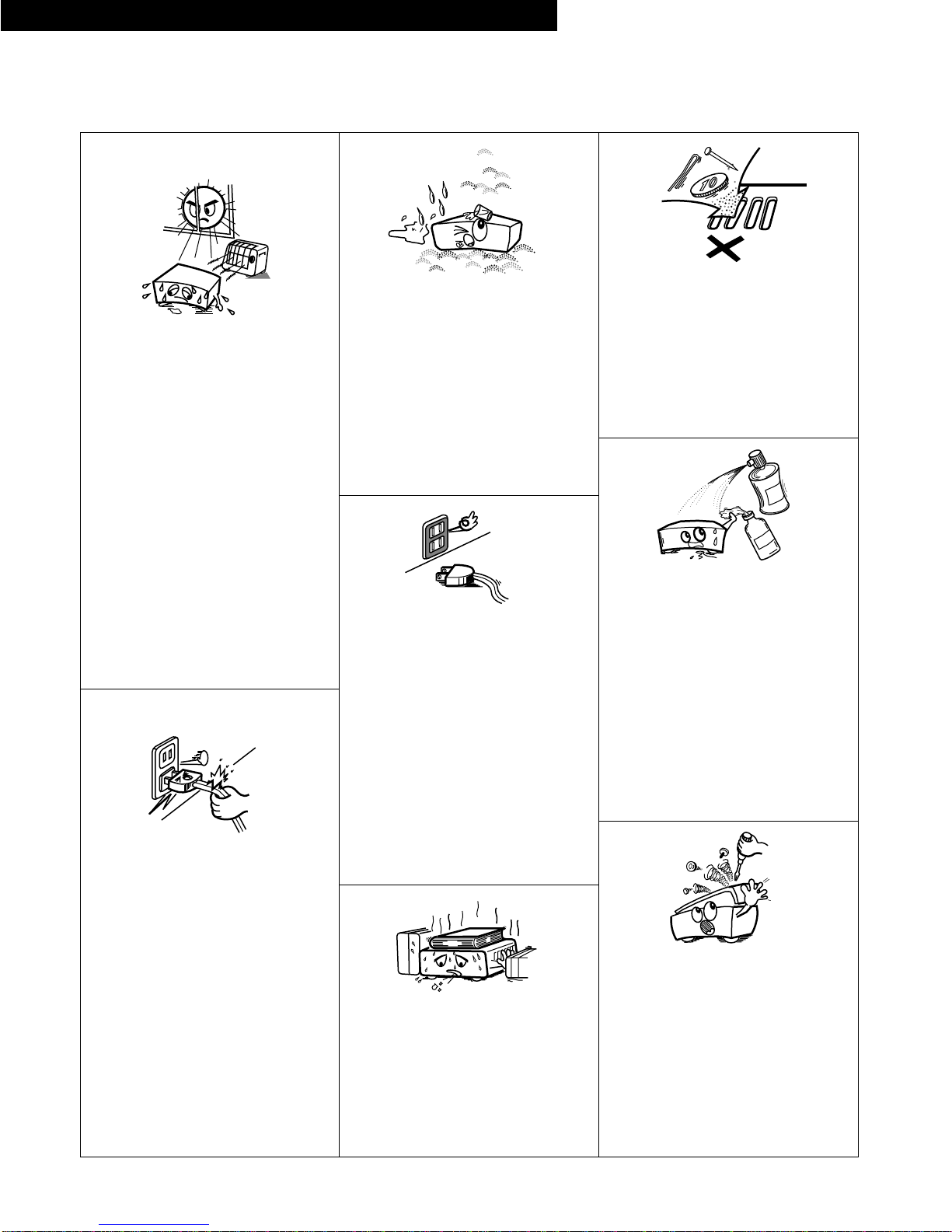
•Avoid high temperatures.
Allow for sufficient heat dispersion when
installed on a rack.
•Vermeiden Sie hohe Temperaturen.
Beachten Sie, daßeine ausreichend
Luftzirkulation gewährleistet wird, wenn das
Gerät auf ein Regal gestellt wird.
•Eviter des températures élevées
Tenir compte d’une dispersion de chaleur
suffisante lors de l’installation sur une étagère.
•Evitate di esporre l’unitàa temperature alte.
Assicuratevi che ci sia un’adeguata dispersione
del calore quando installate l’unitàin un mobile
per componenti audio.
•Evite altas temperaturas.
Permite la suficiente dispersión del calor
cuando estáinstalado en la consola.
•Vermijd hoge temperaturen.
Zorg voor een degelijk hitteafvoer indien het
apparaat op een rek wordt geplaatst.
•Undvik höga temperaturer.
Se till att det finns möjlighet till god
värmeavledning vid montering i ett rack.
•Evite temperaturas altas.
Conceda suficiente dispersão de calor quando o
equipamento for instalado numa prateleira.
•Keep the set free from moisture, water, and
dust.
•Halten Sie das Gerät von Feuchtigkeit, Wasser
und Staub fern.
•Protéger l’appareil contre l’humidité, l’eau et
lapoussière.
•Tenete l’unitàlontana dall’umidità, dall’acqua e
dalla polvere.
•Mantenga el equipo libre de humedad, agua y
polvo.
•Laat geen vochtigheid, water of stof in het
apparaat binnendringen.
•Utsätt inte apparaten för fukt, vatten och
damm.
•Mantenha o aparelho livre de qualquer
umidade, água ou poeira.
•Do not let foreign objects in the set.
•Keine fremden Gegenstände in das Gerät
kommen lassen.
•Ne pas laisser des objets étrangers dans
l’appareil.
•E’importante che nessun oggetto èinserito
all’interno dell’unità.
•No deje objetos extraños dentro del equipo.
•Laat geen vreemde voorwerpen in dit apparaat
vallen.
•Se till att främmande föremål inte tränger in i
apparaten.
•Não deixe objetos estranhos no aparelho.
•Do not let insecticides, benzene, and thinner
come in contact with the set.
•Lassen Sie das Gerät nicht mit Insektiziden,
Benzin oder Verdünnungsmitteln in Berührung
kommen.
•Ne pas mettre en contact des insecticides, du
benzène et un diluant avec l’appareil.
•Assicuratevvi che l’unitànon venga in contatto
con insetticidi, benzolo o solventi.
•No permita el contacto de insecticidas, gasolina
y diluyentes con el equipo.
•Laat geen insektenverdelgende middelen,
benzine of verfverdunner met dit apparaat in
kontakt komen.
•Se till att inte insektsmedel påspraybruk,
bensen och thinner kommer i kontakt med
apparatens hölje.
•Não permita que inseticidas, benzina e
dissolvente entrem em contacto com o
aparelho.
•Never disassemble or modify the set in any
way.
•Versuchen Sie niemals das Gerät auseinander
zu nehmen oder auf jegliche Art zu verändern.
•Ne jamais démonter ou modifier l’appareil
d’une manière ou d’une autre.
•Non smontate mai, nèmodificate l’unitàin
nessun modo.
•Nunca desarme o modifique el equipo de
ninguna manera.
•Nooit dit apparaat demonteren of op andere
wijze modifiëren.
•Ta inte isär apparaten och försök inte bygga om
den.
•Nunca desmonte ou modifique o aparelho de
alguma forma.
•Unplug the power cord when not using the set
for long periods of time.
•Wenn das Gerät eine längere Zeit nicht
verwendet werden soll, trennen Sie das
Netzkabel vom Netzstecker.
•Débrancher le cordon d’alimentation lorsque
l’appareil n’est pas utilisépendant de longues
périodes.
•Disinnestate il filo di alimentazione quando
avete l’intenzione di non usare il filo di
alimentazione per un lungo periodo di tempo.
•Desconecte el cordón de energía cuando no
utilice el equipo por mucho tiempo.
•Neem altijd het netsnoer uit het stopkontakt
wanneer het apparaat gedurende een lange
periode niet wordt gebruikt.
•Koppla ur nätkabeln om apparaten inte kommer
att användas i lång tid.
•Desligue o fio condutor de força quando o
aparelho não tiver que ser usado por um longo
período.
* (For sets with ventilation holes)
•Do not obstruct the ventilation holes.
•Die Belüftungsöffnungen dürfen nicht verdeckt
werden.
•Ne pas obstruer les trous d’aération.
•Non coprite i fori di ventilazione.
•No obstruya los orificios de ventilación.
•De ventilatieopeningen mogen niet worden
beblokkeerd.
•Täpp inte till ventilationsöppningarna.
•Não obstrua os orifícios de ventilação.
•Handle the power cord carefully.
Hold the plug when unplugging the cord.
•Gehen Sie vorsichtig mit dem Netzkabel um.
Halten Sie das Kabel am Stecker, wenn Sie den
Stecker herausziehen.
•Manipuler le cordon d’alimentation avec
précaution.
Tenir la prise lors du débranchement du cordon.
•Manneggiate il filo di alimentazione con cura.
Agite per la spina quando scollegate il cavo
dalla presa.
•Maneje el cordón de energía con cuidado.
Sostenga el enchufe cuando desconecte el
cordón de energía.
•Hanteer het netsnoer voorzichtig.
Houd het snoer bij de stekker vast wanneer
deze moet worden aan- of losgekoppeld.
•Hantera nätkabeln varsamt.
Håll i kabeln när den kopplas från el-uttaget.
•Manuseie com cuidado o fio condutor de
energia.
Segure a tomada ao desconectar o fio.
ESPAÑOL SVENSKA

7
ENGLISH
The DN-M2300R is a rack-mount type double MD recorder equipped with a variety of easy-to-use functions.
MD 1 is for playback only.
MD 2 is for both playback and recording.
[PLAY FUNCTION]
•Instant Start (Playback starts less than 0.03 seconds after the PLAY button is pressed.)
•Hot Start function
Up to five tracks can be preset and played immediately.
•Auto Cue
After a track is selected it is automatically cued to the point where audio starts.
Cueing tracks place at the point where audio starts rather than where the track starts. The level at which sound is first detected can be set
between –36 to –60 dB (5 steps).
•Pitch Control (+8 to –8 %, 0.1 step)
Pitch control with an analog feeling using a pitch slider.
•Pitch Bend (The already adjusted pitch can be changed temporarily.)
•Seamless Loop
Any section can be played repeatedly with no interruption in the sound.
•1/ALL track Repeat mode
•Play mode and Finish mode
1) Play mode
q Continuous: Play a whole disc
w Single: Play a track
2) Finish mode (Stop, Next, Recue)
q Stop: Stop after finishing to play a track
w Next: Cue at the beginning of next track after finishing to play a track
e Recue: After finishing to play a track, cue at the beginning of the track
•End Of Message (EOM)
At the end of a track, the EOM and TRACK NO. flashes, providing a visual warning to the operator that the track will end shortly. The point at
which the flashing begins can be set within a range of 5 to 90 seconds (7 steps) prior to the end of the track.
•Program Play (Max. 25 tracks)
1) When the PLAY mode is set to Single, the player stands by at the beginning of next track.
2) When the PLAY mode is set to Continuous, the playback is continued according to your programmed sequence.
[RECORD FUNCTION]
•Auto Level Rec start
This function automatically starts the recording operation when an audio signal level from an external unit connected to the DN-M2300R exceeds
the preset level (–36 to –66 dB, 6 steps and off).
•Auto Track Increment
DN-M2300R detects the silent portion of the program material and automatically increases the track number. The level of the silent portion can be
set within a range of –36 to –60 dB (5 steps).
•Stereo/Mono recording (74/148 min.)
•Using CUE Signals to make searches (Up to 5 points per track)
•Editing
1) Basic Editing
•DIVIDE: Smallest edited unit is 11.6 msec (1 sound group)
•ERASE TRACK/DISC/CUE
•COMBINE
•MOVE
•TRACK NAME
•DISC NAME
Up to 100 characters can be used for each name, however, the combined total number of characters cannot exceed 1700.
2) Cue signals also can be edited. (Can be erased, rewritten, or added to later.)
•Undo function
Undo function during editing. (Up to 2 editing operations prior to the most recent one can be undone.)
•SCMS
Recording is possible without reception of the copy defeat restriction. Writing of the copy defeat code is selectable.
•1 /2 SYNCHRO REC
This is a function for easily recording tracks from MD 1 onto MD 2.
•19 inch Rack Mountable (Height: Player: 2 U Remote: 3 U)
•Large FL Display
•Track Search Select knob (Easy track selection)
•Search/Scan dial
Perform searches to 1 sound group precision using the dial and easy scans using the scan dial.
MAIN FEATURES

8
ENGLISH
CONTENTS
zPART NAMES AND FUNCTIONS ……………………………9 ~ 11
(1) Front Panel …………………………………………………9, 10
(2) Rear Panel ………………………………………………………10
(3) Display Window ………………………………………………11
xABOUT MINIDISCS …………………………………………………11
cBASIC OPERATIONS …………………………………………12 ~ 16
(1) Before Starting Playback (MD 1, MD 2) ……………………12
(2) Starting Playback (MD 1, MD 2) ……………………………12
(3) Stopping Playback ……………………………………………12
(4) PLAY/PAUSE and CUE Operations (MD 1, MD 2) ………13
(5) Before Starting to Record (MD 2 Only) ……………………13
(6) Method of Recording on Discs (MD 2 Only) ………………13
(7) Starting to Record (MD 2 Only) ………………………………14
(8) Stopping Recording ……………………………………………14
(9) Starting Recording Automatically by
Detecting the Input Level (MD 2 Only)………………………15
(10) Stopping Recording ……………………………………………15
(11) Incrementing Track Numbers (MD 2 Only) …………………16
(12) Pre-UTOC Function (MD 2 Only) ……………………………16
vHANDY OPERATIONS ………………………………………17 ~ 22
(1) Starting Playback from the Middle of a Track
(Manual Search) (MD 1, MD 2) ………………………………17
(2) Playing at a Different Speed (Pitch) (MD 1, MD 2)…………17
(3) Seamless Loop (MD 1, MD 2) ………………………………18
(4) Instantaneous Play (Hot Start) (MD 1, MD 2) ………………19
(5) Setting Cue Points (MD 2 Only)………………………………20
(6) Direct Search for Cue Points (MD 1, MD 2) ………………21
(7) 1 /2 SYNCHRO REC Function (MD 1, MD 2) ……………21
(8) External monitor function (MD 2 Only)………………………22
(9) OTHER FUNCTION (MD 1, MD 2) …………………………22
bPROGRAMMED PLAYBACK (MD 1, MD 2) ………………23 ~ 25
(1) Inputting Programs ……………………………………………23
(2) Changing Programs ………………………………………23, 24
(3) Playing Programs ………………………………………………24
(4) Presetting Programs …………………………………………25
nEDITING FUNCTIONS (MD 2 Only) …………………………26 ~ 32
(1) Editing Functions ………………………………………………26
(2) Erasing Tracks ‹Track erase function› ………………………27
(3) Erasing All the Tracks on the Disc
‹All erase function› ……………………………………………27
(4) Erasing Cue Signals ‹Cue erase function› …………………28
(5) Dividing Tracks into Two Parts ‹Divide function› …………28
(6) Combining Two Tracks ‹Combine function› ………………29
(7) Moving Tracks ‹Move function› ……………………………29
(8) Inputting (Changing) Names ‹Title function› ………………30
(9) Exit the Edit Mode or Undoing Editing
‹Undo functions› ………………………………………………31
(10) Error Messages ………………………………………………32
mPRESET FUNCTIONS AND OPERATIONS
(MD 1, MD 2) ……………………………………………………33, 34
(1) Preset Functions ………………………………………………33
(2) Presetting Procedure …………………………………………33
(3) Detailed Description of Preset Functions …………………34
,HANDLING CARTRIDGES …………………………………………35
.MESSAGES …………………………………………………………35
⁄0 SYSTEM LIMITATIONS ……………………………………………36
⁄1 SPECIFICATIONS ……………………………………………………37
Checking the Contents
Check that the carton contains the following items in addition to the main unit.
qOperating instructions ……………………………………………1wConnection cords for signal output (RCA) ……………………3
eRemote control unit (RC-45) ……………………………………1rRemote control connection cable ………………………………1
Installing the Units
Mount the units onto your console or rack with 19”EIA rack rails.
•DECLARATION OF CONFORMITY
We declare under our sole responsibility that this product, to which this declaration relates,
is in conformity with the following standards:
EN60065, EN55013, EN55020, EN60555-2 and EN60555-3.
Following the provisions of 73/23/EEC, 89/336/EEC and 93/68/EEC Directive.
Caution on handling
Do not move or transport the recorder with a disc loaded. Doing so may scratch the disc or damage the recorder.
CAUTION:
•If the power is turned off during the recording pause, recording, playing, UTOC write or editing
mode, the cartridge cannot be ejected when the power is off.
•If the cartridge cannot be ejected when the power is off, turn on the power to eject it.
•Be sure turn on POWER switch after a Remote cable of RC-45 is connected to the Player unit,
otherwise, the apparatus may not work correctly.
•DN-M2300R (RECORDER UNIT) and RC-45 (REMOTE CONTROL UNIT) are designed exclusively to
connect each other. Do not connect it to a different model. Otherwise the unit may be damaged.
•Be sure to use the remote control connection cable which has been supplied. Use of another cable
type might cause damage.

9
ENGLISH
(1) Front Panel
qLEVEL control
•Use this to adjust the volume of the headphones.
wPHONES jack
•Connect headphones with an impedance of 30 to 40 Ω/ohms.
eCartridge insertion slot
•Insert the cartridge as indicated by the arrow on the top.
•Press the cartridge to the back of the slot until it is set.
rEJECT button
•Press this button to eject the cartridge.
•The cartridge cannot be ejected during recording, playing,
editing or while the UTOC is being written.
tPLAY MODE button
•When this button is pressed, the play mode switches.
yTIME button
•Press this button to switch the time display between the
remaining time (REMAIN) and the elapsed time (ELAPSED).
uNAME/CAPS button
•When this button is pressed, the character display switches
between the disc name and track name, in that order.
•When the button is pressed while editing names, the selected
characters switch between capital letters, small letters,
numbers and symbols, in that order.
iLOOP button
•Press this to start the loop mode (A-B loop, 1/All repeat, or hot
start repeat play).
•The LED lights during loop playback.
oA button
•Press this to set the starting point for loop playback.
!0 B button
•Press this to set the ending point for loop playback.
!1 EXIT/RELOOP button
•When this button is pressed during loop playback, loop
playback stops and the normal play mode is set (EXIT). When
pressed again, loop playback resumes.
!2 REC LEVEL control
•Use this to adjust the level of the analog input signal.
!3 PITCH button
•When this button is pressed, the playing speed can be
changed using the pitch slider.
•The LED lights when the pitch play mode is set.
•Press the button again to cancel the pitch play mode and
return to the normal speed.
!4 PITCH BEND –and + button
•The pitch increases or decreases while one of these button is
pressed.
•The pitch returns to the previous value when the button is
released.
!5 POWER button
•This turns the set on and off.
!6 SCAN dial (outer side)
•Turn this dial to set the manual search (fast forward or fast
reverse) mode.
•Turn the dial clockwise to move the playback position forward,
counterclockwise to move the playback position backward.
•The speed changes according to the angle at which the dial is
turned.
!7 SEARCH dial (inner side)
•Turn this dial to set the manual search mode.
•Turn the dial clockwise to move the playback position forward,
counterclockwise to move the playback position backward.
•One click corresponds to one frame of movement. The
playback position can be moved anywhere between the
beginning of the first track and the end of the last track.
!8 CUE SEARCH button
•When this button is pressed during the cue, pause, search or
play mode, the cue signal point direct search mode is set.
When pressed again, the direct search mode is canceled.
•The LED lights when the direct search mode is set.
!9 CUE button
•When this button is pressed during the play or pause mode,
the pickup returns to the position at which playback started
and the cue mode is set. (Back Cue)
•The LED lights when the cue mode is set.
•When the button is pressed during the recording or recording
pause mode, recording stops, the pickup returns to the
recording start position and the cue mode is set.
•When this button is pressed in the cue direct search mode,
the cue point is searched for.
•When this button is pressed during hot start playback,
playback stops.
•When press during hot start loading, hot start is canceled.
(The data loaded before the button is pressed is valid.)
•When the button is pressed while pressing the PLAY MODE
button, the preset mode is set.
@0 CUE WRITE button
•Press this button during the cue, pause, play, or manual
search. When the edit mode and recording mode to record a
cue signal.
@1 PLAY/PAUSE button
•Press this button in the cue, pause or manual search mode to
begin playback.
•Press the button in the stop mode to search for the first track
and begin playback.
•When the button is pressed in the recording pause mode,
recording starts.
•The LED lights when the play or recording mode is set.
•When the button is pressed during playback, the pause mode
is set. The LED flashes while the pause mode is set.
•When the button is pressed during recording, the recording
pause mode is set. The LED flashes when the recording
pause mode is set.
Caution on ejecting cartridge
•Do not try to pull out a partially inserted cartridge. Doing
so may damage it.
PART NAMES AND FUNCTIONS
1

10
ENGLISH
@2 REC button
•When this button is pressed during the stop, cue or pause
mode, the recording pause mode is set.
•When the button is pressed during recording, the track
number is incremented.
•The LED lights when the recording or recording pause mode
is set.
•The external source can be monitored by pressing in the
button for at least 3 seconds.
@3 EDIT/INPUT button
•Press this button to set the edit mode.
•The “”lights when the edit mode is set.
•When the button is pressed during the edit mode, the edit
mode is canceled.
•Press this button in the recording pause mode to switch
between analog and digital, according to the input signal.
@4 Select knob
•When this knob is turned during playback, the selected track
is searched for.
•Turn the knob clockwise by one click to move one track
forward, counterclockwise by one click to move one track
backward.
•When the knob turned while pressing it in, one click
corresponds to 10 tracks.
•In the preset mode, use this knob to set and enter preset
setting.
•When setting programs, use this knob to select, enter and
check the program.
•In the cue point direct search mode, use this knob to select
the cue point.
@5 PROGRAM ON/OFF button
•Operates when button “1”or “2”is pressed while pressing
this button.
•When this button is pressed while the PROGRAM indicator is
lit, the program play mode is set.
•The button will not function during the LOOP mode.
@6 PROGRAM IN button
•Operates when button “1”or “2”is pressed while pressing
this button.
•Press this button to set the program input mode.
•The button will not function during the play mode.
•The PROGRAM indicator flashes when in the program input
mode.
@7 ~ (number) buttons (Hot start buttons)
•Press the desired button to start hot start playback.
@8 ERASE button
•Press this button in the edit mode to set the erase mode (to
erase discs, tracks or cue points).
•When this button is pressed again after selecting the item to
be erased, “*** OK?”appears on the display. Press the
button again to erase the selected item.
@9 DIVIDE button
•Press this button in the edit mode to set the divide mode (to
divide a track in two).
•When the button is pressed again after checking the divide
point, the track is divided and the divide mode is canceled.
#0 COMBINE button
•Press this button in the edit mode to set the combine mode
(to combine tracks).
•When the button is pressed again after checking the tracks,
the tracks are combined.
51
EDIT
#1 MOVE button
•Press this button in the edit mode to set the move mode (to
move tracks).
•When this button is pressed again in the move mode after
selecting the number to which the track is to be moved, the
track is moved.
#2 TITLE IN button
•Press this button during the editing mode to set the name
input mode.
•When this button is pressed after inputting the name, the
input name is entered.
#3 LOAD button
•Operates when button “1”or “2”is pressed while pressing
this button.
•When this button is pressed in the cue and pause mode, the
data for five tracks starting from the track at which the cue
and pause mode is set is loaded into the hot start memory.
#4 Pitch slider
•Use this to adjust the pitch.
•The pitch decreases when the slider is moved upwards and
increases when the slider is moved downwards.
#5 1 /2 button
•The mode for recording from MD 1 onto MD 2 is set.
MD 1 is set to the standby or pause mode, MD 2 to the
recording standby mode.
•When the button is pressed during copying, MD 1 is set to the
pause mode, recording stops on MD 2, the UTOC is written,
and the standby mode is set at the track at which recorded
started.
#6 “1”“2”HOT START/PROGRAM
•Press one of these buttons while pressing the LOAD,
PROGRAM ON/OFF or PROGRAM IN button.
(2) Rear Panel
qANALOG OUT jacks
•These are analog outputs using RCA type jacks.
wANALOG IN jacks
•These are analog inputs using RCA type jacks.
eDIGITAL IN jacks
•This is a digital input using an RCA type jack.
•Signal format: SPDIF or IEC 958 Type II.
rDIGITAL OUT jacks
•This jack outputs digital data.
•We recommend using a 75 Ω/ohms pin cord (available in
stores) for connections.
•Signal format: (CueDet.: Preset. 2)
CueDet. OFF: SPDIF/CueDet. –60 ~ –36 dB: IEC 958 Type II.
tREMOTE (Remote Control Connector)
•This connector accepts the cable which connects to the
remote control unit RC-45. Insert the plug securely as far as it
will advance.
WARNING:
Turn PITCH control OFF when making digital recordings.
Most digital recorders will not accept a variable pitched
digital signal.

11
ENGLISH
(3) Display Window
qDISC NAME/TRACK NAME indicators
•“DISC NAME”lights when the disc name is displayed on the
character display, “TRACK NAME”lights when the track
name is displayed.
wPROGRAM indicator
•This lights when the Program play mode is set.
eTRACK NO. display
•This displays the number of the track at the current position.
This also lights during the track search mode and when
switching to the cue mode.
rCharacter display
•This displays disc names, track names.
•Various instructions are displayed here during presetting,
programming, editing, etc.
tPlaying time display
•This indicates the time of the current position, in minutes (m),
seconds (s) and frames (f).
yPLAY MODE indicators
•“SINGLE”lights when in the single track play mode.
uTIME MODE indicators
•“ELAPSED”lights when the elapsed time is displayed.
•“REMAIN”lights when the remaining time is displayed.
iTRACK NO. indicators
•TRACK NO.: Indicates that the track number display shows
the selected track number.
•NEXT: Indicates that the displayed track number is the
reserved track number when presetting 14,
“Reserve”is set to “ON”.
oTOC indicator
•This lights when it is necessary to rewrite the TOC (UTOC)
due to editing, etc
•This flashes while the TOC (UTOC) is being written.
!0 EDIT indicator
•This lights when the edit mode is set.
!1 DIGITAL IN indicator
•This lights (or flashes) when the digital input signal is selected.
•The indicator flashes when the digital signal is unlocked and
remains lit when the digital signal is locked.
!2 Level display
•This displays the playback level during playback, the input
level during recording.
!3 PITCH display
•This indicates the set play speed in %.
•The program number is displayed during program input and
editing.
!4 EOM indicator
•This lights when the EOM is preset, and starts flashing when
the EOM set time is reached.
!5 CUE indicator
•This lights for approximately 3 seconds when the position at
which a cue signal is set is played.
•The indicator flashes when the cue mode is set at a position
at which a cue signal is set.
!6 EJECT LOCK indicator
•When this indicator is lit, the eject lock function is set and the
cartridge is not ejected even when the eject button is
pressed.
!7 REPEAT indicator
•When this indicator is lit, playback is repeated.
ABOUT MINIDISCS
2MiniDiscs allow a maximum of 74 minutes (stereo) of recording and
playback in a compact size.
There are two types of MiniDiscs: those for playback only, and
those for recording and playback.
Playback only MiniDiscs
•These discs are for playback only. Commercially
available music MDs are of this type.
•These are laser discs, like regular compact discs.
•Tracks on such discs cannot be edited.
m
m
Recordable MiniDiscs
•These are magneto-optical discs on which both
recording and playback are possible. Recording is
performed through magnetic modulation.
•Re-recording is also possible.
Accidental erasure prevention tabs
These tabs protect recordable MiniDiscs from accidental erasure.
To avoid accidentally erasing the recording, open the tab so that the
hole is exposed. (See the diagram below.) When this is done,
“Protected”is displayed if you attempt to record, erase or otherwise
edit the disc, and the recording is protected. To record or erase the
disc, set the tab back to its original position (with the hole covered).
Hole exposed
Slide the tab
Recording on discs
MiniDiscs include a section in which the audio signals are recorded and
a section in which such data as track numbers and track titles are
recorded.
m
2The TOC
With MiniDiscs, after the audio signals are recorded, data used for
checking the tracks (TOC–Table of Contents) is also recorded on the
disc. This TOC data is used when playing the disc. In addition,
editing is performed by rewriting the TOC data.
When TOC writing starts, the “”indicator flashes. Do not
shake the main unit, press the main unit’s power button or unplug
the power cord while the TOC is being written. If the data is not
recorded properly, it will not be possible to play the disc.
2Handling MiniDiscs
MiniDiscs are housed in cartridges, so there is no need to worry
about dirt and scratches. However, dirty or warped cartridges may
cause malfunction. Be careful of the following to ensure long-
lasting, high quality sound:
•Do not touch the disc surface directly.
•Do not open the shutter by hand.
•Do not place MiniDiscs in dusty, dirty or humid places.
•Do not place MiniDiscs in places exposed to direct sunlight or high
temperatures.
Cleaning
Use a dry cloth to gently wipe dirt or dust off the cartridge. Do not
apply excessive force.
TOC
Section in which audio
signals are recorded
Section in which track
numbers and track titles
are recorded (TOC)
2

12
ENGLISH
DISC NAME
dB -00 -40 -20 -12 -6 -2 0 OVER PITCH %
R
L
msf
TRACK NO. SINGLE REMAIN NEXT NO.
EOM
SINGLE
SINGLE
BASIC OPERATIONS
(1) Before Starting Playback (MD 1, MD 2)
1
2
Make the presettings according to the usage purpose.
(See Page 34)
NOTE: Steps 1 and 2 can be performed in the opposite
order.
3
4
5-1
5-2
Select the play mode.
Press the PLAY MODE button.
Load the cartridge.
Single track play mode
Continuous play mode
Select the track to be played.
Turn the select knob (8–9).
TRACK NO. TRACK NO.
EJECT LOCK
The selected track is cued and the cue mode is set.
To check the play start position.
Press the PLAY/PAUSE button.
Monitor the playback signals to check the play start
position.
EJECT LOCK
The pickup returns to the play start position and the cue
mode is set. (Back Cue)
Press CUE button.
Flashing during
search Lit when in cue
6
Start playback.
Press the PLAY/PAUSE button.
Playback begins and the playback signals are output.
(2) Starting Playback (MD 1, MD 2)
(3) Stopping Playback
7
Playback can be stopped in the following ways.
Playback is interrupted, the pickup
returns to the play start position and the
cue mode is set.
Lit
Lit Off
Lit
Flashing
Lit
Lit Off
Playback is interrupted and
the pause mode is set at that
point.
Sleep mode.
The sleep mode is set if no operation is performed for 30/20/10
minutes in the cue, pause mode.
(Select the time with the presettings.)
When in the sleep mode, press the PLAY/PAUSE button to
search for the position before the sleep mode was set and start
playback. Press the CUE button to search for the position before
the sleep mode was set and cue at that point.
Flashing
Flashing
3
3 5-
2
,7 4 3 5-
2
,7 4
1 5-
1
,6,7 1 5-
1
,6,7
Lit
Off

13
ENGLISH
(4) PLAY/PAUSE and CUE Operations (MD 1, MD 2) (5) Before Starting to Record (MD 2 Only)
(6) Method of Recording on Discs (MD 2 Only)
•The operation switches between playback and pause each time
the PLAY/PAUSE button is pressed.
•When the CUE button is pressed during playback, the pickup
returns to the position at which playback was started.
The diagrams below show playback patterns when the
PLAY/PAUSE and CUE buttons are pressed.
PLAY and PAUSE
When the PLAY/PAUSE button is pressed, playback starts and
proceeds as shown by the arrow on the diagram above.
If the PLAY/PAUSE button is pressed again during playback, the pause
mode is set at that point. Press the PLAY/PAUSE button again to
resume playback.
PLAY/PAUSE
button
pressed
PLAY/PAUSE
button
pressed PLAY/PAUSE button pressed
Position on disc
Pause mode set at this point
Section
played
Section
played
PLAY and CUE
PLAY, PAUSE and CUE
Back Cue
PLAY/PAUSE
button
pressed CUE button pressed
Position on disc
Section
played
When the CUE button is pressed after starting playback by pressing
the PLAY/PAUSE button, the pickup returns to the position at which
playback was started and prepares for the next playback.
Press the PLAY/PAUSE and CUE buttons alternately to start playback
repeatedly from the same position.
This function is called “Back Cue”.
PLAY/PAUSE
button
pressed
PLAY/PAUSE
button
pressed
PLAY/PAUSE
button
pressed CUE
button pressed
Position on disc
Section
played
Section
played
If the pause mode is set and playback is then resumed, the position to
which the pickup returns with the Back Cue function changes.
•Turn on the power. To record from the analog input, it is
recommended to turn on the power at least 5 seconds before
starting to record. This eliminates fluctuations of the A/D
converter DC offset, reduces the amount of DC offset at the
recording start position, in the middle of the recording and at
the recording end position, and keeps the DC offset constant.
DC offset hinders the auto cue function for detecting the point
where the sound starts at low levels and the auto track
increment function which detects soundless sections.
•Load a recordable disc. There are 60-minute and 74-minute
recordable discs. For a description of recordable discs, see the
section “Method of Recording on Discs”below. It is not
possible to record on discs which are already recorded and
have little free space left or on playback only discs.
Disc for recording Method of recording on disc
1Discs on which
nothing is recorded
Recording starts from the begin-
ning of the disc.
The beginning of the disc is
found automatically, so there is
no need to do this manually.
2
Recording on discs
after erasing all their
tracks
Same as above.
3
Recording on an
already recorded
disc
Recording starts from the end of
the last recorded section.
The end of the last recorded
section is found automatically, so
there is no need to do this
manually.
The set is designed so that it is
not possible to record over a
recorded section, so you cannot
accidentally erase a previous
recording.
4
Recording on discs
after erasing part or
all of the disc
If there is not enough remaining
space or if you want to do the
recording over, erase before
recording.
To erase one track at a time:
Use the track erase function.
To erase all the tracks at once:
Use the all erase function.
•Disc types
Blank discs: Discs on which nothing is recorded
Discs you have just bought
Discs that have been erased (using the all
erase function)
No-track discs: Discs on which nothing is recorded but which
contain a disc name
Blank discs which have been given a disc
name
Discs with disc names on which all the tracks
have been erased individually

DIGITAL IN
DIGITAL IN
NOTE:
If the DIGITAL IN indicator is flashing, the digital signal
is unlocked. If this is the case, recording is not
possible.
If the MD1 pitch is operated when recording with MD1
selected as the input, noise will be generated and
recording will stop. Turn the MD1 pitch off when
recording with MD1 selected as the input.
Digital input mode
Analog input mode
Lit or flashing
14
ENGLISH
msf
TRACK NO. SINGLE ELAPSED NEXT NO.
EJECT LOCK
(7) Starting to Record (MD 2 Only)
1
2
Set the presettings according to the purpose.
(Refer to Page 34)
5) Rec Lv. OFF
Recording starts, regardless of the input level.
3
4
5
Set the recording pause mode.
Press the REC button.
Load the cartridge.
Flashing
For a disc on which 3 tracks are already
recorded.
The disc’s total number of tracks and playing time are
displayed.
Set the input signal.
Press the EDIT/INPUT button and switch between analog
and digital, according to the input signal.
(ANALOG /DIGITAL 1 /DIGITAL 2 /MD 1)
Adjust the recording level.
When recording analog inputs, use the Rec LEVEL
controls to adjust the recording level.
Lit
Adjust so that the level meter’s “OVER”
indicator does not light even when the
maximum level is input.
EJECT LOCK
6
7
8
Recording starts and the indicator lights.
•The disc and track name can be input during recording.
Refer to “(8) Inputting Names”(P30) steps 5 to 9.
Note that name input is automatically stopped when
the track is incremented.
TOC
Start recording.
Press the PLAY/PAUSE button.
To change the track number during recording.
Press the REC button.
To pause recording:
Press the PLAY/PAUSE button.
9
Stopping recording.
The indicator flashes while the UTOC is being
written.
TOC
Recording stops and the recording pause mode is set.
To resume recording, press the PLAY/PAUSE button
again. The track number is incremented and recording
resumes.
EJECT LOCK
Lit
Lit
The track number is incremented and recording
continues.
Lit
Flashing
(8) Stopping Recording
EJECT LOCK
Recording stops, the UTOC is written
and the standby mode is set.
Lit once in cue
Turns off after UTOC is written
Lit
Lit
Lit
3,7 94
15 6,8

15
ENGLISH
msf
TRACK NO. SINGLE ELAPSED NEXT NO.
EJECT LOCK
1
2
3
4
Set the recording pause mode.
Press the REC button.
Set the presettings according to the purpose.
(Refer to Page 34)
5) RecStart (–**) dB
Recording starts when a signal with a level at or
above the set level is input.
Off
For a disc on which 3 tracks are already
recorded.
The disc’s total number of tracks and playing time are
displayed.
Set the input signal and input level.
Set the input signal and input level, referring to steps 4
and 5 under “Starting to Record”on Page 14.
Lit
5
To pause recording:
Press the PLAY/PAUSE button.
Recording stops and the recording pause mode is set.
To resume recording, press the PLAY/PAUSE button
again. The track number is incremented and recording
resumes.
EJECT LOCK
Lit
Off
Lit
Lit
(9) Starting Recording Automatically by Detecting the
Input Level (MD 2 Only)
EJECT LOCK
Recording starts when an input signal with a level at or
above the set level is detected.
Start recording.
Press the PLAY/PAUSE button.
Lit
Flashing
Lit
When the PLAY/PAUSE button is pressed in the input
signal detection mode, recording starts immediately.
Lit Lit
During recording
4
(continued)
NOTE:
The auto track increment function and Auto Level Rec strart
function may not work when recording analog signals containing
much noise. In this case lower the detection level to for
example –54 dB.
6
Stopping recording.
The indicator flashes while the UTOC is being
written.
TOC
(10) Stopping Recording
EJECT LOCK
Recording stops, the UTOC is written
and the standby mode is set.
Lit once in cue
Turns off after UTOC is written
2 6
4,5

16
ENGLISH
1) Detection of soundless section
qMake the following two presettings:
•Set “Auto Inc OFF”(3) to “Auto Inc Det.”
•Set the soundless detection level setting to “Inc. Det.-
(48) dB”(4).
wStart playback and recording in such a way that the
beginning of the sound is not missed. When a soundless
section (or a section with level lower than the preset
soundless detection level setting) of at least 2 continuous
seconds is detected, the disc’s track number is
automatically incremented.
(11) Incrementing Track Numbers (MD 2 Only)
During recording, track numbers can be incremented either
manually or automatically.
•Track numbers can be incremented manually in the following
four ways:
1) Press the REC button (4) during recording. This increments
the track number.
2) Press the PLAY/PAUSE button (13) during recording to
stop recording for that track number and set the recording
pause mode. When the PLAY/PAUSE button (13) is
pressed again, recording starts with a new track number.
3) After recording, use the divide function.
•Track numbers can be incremented automatically in the
following three ways, according to the type of input signal:
Input type Method
Detection of soundless section 1)
Using the CD’s or MD’s subcodes 2)
Detection of soundless section 1)
Using the DAT’s start IDs 3)
Analog/digital input
Digital input
CDs
and
MDs
DATs
2 seconds or more
Track number is incrementedSoundless section
NOTE: The auto track increment function may not work when
recording analog signals containing much noise. In this case
lower the detection level to for example –54 dB.
2) Using the CD’s or MD’s subcodes (digital input)
qMake the following presetting:
•Set “Auto Inc OFF”(3) to “Auto Inc Dig.”
wStart playback on the CD (MD) player and recording on the
recorder in such a way that the beginning of the sound is
not missed. The disc’s track number is automatically
incremented when the CD’s (MD’s) track number changes.
Changes in the CD’s (MD’s) track number will not be
detected for approximately 4 seconds after the track
number is incremented.
NOTE:
The auto track increment function using the DAT’s start ID or the CD’s sub codes will not work if the digital input is in professional format
(AES/EBU). Input digital signals of the consumer format (SPDIF).
CD/MD
MD
123
12345
Copy
Track
number
Track A Track B Track X Track Y Track Z
Previously recorded
tracks Tracks recorded from
the CD (MD)
Start of recording
Start of recording End of recording
Track X Track Y Track Z
Track
number
DAT
MD
123
12345
Copy
Track
number
Track A Track B Track X Track Y Track Z
Previously recorded
tracks Tracks recorded
from the DAT
Start of recording
Start of recording End of recording
Track X Track Y Track Z
Track
number
3) Using the DAT’s start IDs (digital input)
qRecord the start ID on the recorded DAT.
wMake the following presetting:
•Set “Auto Inc OFF”(3) to “Auto Inc Dig.”
eStart playback on the DAT player and recording on the
recorder in such a way that the beginning of the sound is
not missed. The disc’s track number is automatically
incremented when the DAT’s start ID is detected. The start
ID will not be detected for 15 seconds after the track
number is incremented.
(12) Pre-UTOC Function (MD 2 Only)
•Presetting must be set.
This function protects the recording should the power supply be
cut off. The UTOC is written directly after recording starts.
(The pre-UTOC is written.)
Normally the UTOC is written after recording is completed, so if
the power supply should be cut off during the recording or
directly after the recording is finished, the recording will not be
registered on the disc. To prevent this, the pre-UTOC (*1) is
registered on the disc directly after recording starts. Once
recording is completed normally, the actual UTOC (*2) is written.
If the power should be cut before the actual UTOC is written, the
disc can be played according to the pre-UTOC. This way you
never accidentally lose recordings that cannot be made over
again.
01Tr 02Tr 03Tr
01Tr 02Tr 03Tr
Pre-UTOC (*1)
Entire disc
Start of recording
End of recording
UTOC (*2)
If some problem occurs and recording is interrupted, the same
recording and UTOC can be written using the following editing
operation:
Use the divide function at the point where recording was
interrupted in track 03 on the above diagram to divide the track,
then use the erase function to erase track 04.
Input signal

17
ENGLISH
HANDY OPERATIONS
(1) Starting Playback from the Middle of a Track
(Manual Search) (MD 1, MD 2)
1-1
Find the play start position.
Turn the SEARCH dial.
1-2
2
3
The fast forward/reverse mode is set
when the SCAN dial (outer side) is
turned.
The speed changes according to the
angle at which the dial is turned.
Turn the SCAN dial to change the playback position
quickly.
•When operated during playback, playback resumes
after the operation.
To check the play start position.
Press the PLAY/PAUSE button.
Monitor the play signal to check the play start position.
The pickup returns to the play start position and the cue
mode is set.
Cue the play start position.
Press the CUE button.
•When a track is selected and PLAY/PAUSE button is pressed,
playback starts from the beginning of that track. To start from a
different position in the track, use the procedure described
below to find the desired position.
(2) Playing at a Different Speed (Pitch) (MD 1, MD 2)
There are two ways to change the playing speed.
•Adjust the Pitch using the pitch slider (±8 %).
•Press a PITCH BEND button to temporarily change the Pitch.
Use this after adjusting the Pitch with the pitch slider.
When the dial is turned clockwise, the playback position moves
as follows:
Listen to the sound and find the desired play start position.
Backward Forward
Backward Forward
Playback starts.
Lit
DISC NAME
dB -0 -40 -20 -12 -6 -2 0 OVER PITCH %
R
L
msf
TRACK NO. SINGLE REMAIN NEXT NO.
EOM
Lit
Flashing
1-1
1-2
2
Pitch slider.
Set the variable speed mode.
Press the PITCH button.
The Pitch decreases when the pitch slider is moved
upwards, increases when the pitch slider is moved
downwards.
Pitch bending.
Press the PITCH BEND + (or PITCH BEND –) button.
•The Pitch increases or decreases temporarily while the
PITCH BEND + or PITCH BEND –button is pressed.
•The extent to whitch the PITCH BEND button changes
the Pitch is proportionate to the amount of time the
button is pressed. The longer the button is held down,
the greater the percentage of change.
•The Pitch changes within a range of ±9.9 %.
•The diagram below shows how the PITCH BEND
function is used. In this example, the MD 1 and MD 2
are playing and the Pitch is already matched using the
pitch slider.
NOTE:
When the play speed (PITCH) is set, the display shows the set
pitch, but the disc is played at the standard speed until the
PITCH button is pressed (and the LED is lit).
When PITCH is lit, the sound skips if the pitch slider is operated
continuously.
Lit
Pitch down
Pitch up
MD 2
bass beat
MD 1
bass beat
Pitch are matched but
the bass beats are off The bass beats are
match
Bass beat
Bass beat off
4
231-
1
,1-
2
231-
1
,1-
2
1-
1
21-
2
1-
1
21-
2
When the SEARCH dial (inner side) is
turned, the frame move mode is set.
The playback position moves one frame
for each click.
msf f f

18
ENGLISH
(3) Seamless loop (MD 1, MD 2)
1
Starting seamless loop playback.
Start playback.
Press the PLAY/PAUSE button.
4When the ending point (B) is
set, playback starts from the
starting point (A) with no
interuption in the sound.
5
7
•When the ending point (B) is reached, playback
continues without returning to the starting point (A).
Starting
point
Set the seamless loop mode.
Press the LOOP button.
2
Set the starting point (A).
Press the A button.
3
Set the ending point (B).
Press the B button.
After this, the section between
the starting point (A) and the
ending point (B) is played
repeatedly with no interuption in
the sound.
Ending
point
Starting
point Ending
point
Seamless loop
NOTE: It is not possible to use the seamless loop mode at the
same time as the hot start play or programmed play
mode.
Alternative way to set the seamless loop starting point (A)
and ending point (B).
•After setting point A, set the cue mode, press button A, then
use the scan or search function to fine-adjust point A. (The
same can be done for point B.)
Leaving the seamless loop mode tenporarily.
Press the EXIT/RELOOP button while playing a seamless
loop.
Starting point Ending point
Replaying a seamless loop.
Press the EXIT/RELOOP button or button B during normal
playback.
(The position at whitch button B is pressed is set as the
new loop playback ending point (B).)
6
Starting
point
Ending point
Press the EXIT/RELOOP
button or button B
•Playback returns to the starting point (A) and seamless
loop playback begins.
Switching from seamless loop playback to normal disc
playback (Setting the normal playback mode without
canceling the starting and ending points).
Press the LOOP button within 1 second.
•The normal playback mode is set.
(
Only the loop mode is canceled. Point A and B are not
cleared
)
NOTE:
The starting point (A) and ending point (B) settings are
canceled when the cartridge is removed from the
recorder.
Canceling the seamless loop setting.
Press the LOOP button for over 1 second.
•When this done, the starting point (A) and ending point
(B) settings are automatically canceled.
8
NOTE:
After canceling the seamless loop during loop
playback, it may take about 5 seconds before the
seamless loop mode is set again.
Lit
Lit
Lit
Flashing
Flashing
Lit
Flashing Lit
Starting point Ending point
OffLit
Lit Lit Lit Off Off Off
Select “A-B LOOP”for the “LOOP BUTTON FUNCTION”
presetting.
12,7,8 3 4 5,6 12,7,8 3 4 5,6
Lit

19
ENGLISH
4Tr
No.1 No.2 No.3 No.4 No.5
5Tr 6Tr 7Tr 8Tr 9Tr
[1]Loading..
(4) Instantaneous play (Hot Start) (MD 1, MD 2)
Data loading.
Set the cartridge and cue or pause at the track for hot
start playback.
1
•When the data loading is completed, the CUE LED will
light and the unit will be set to instantaneous play (Hot
Start) standby. 2
[3]Loading..
5 TRACK LOAD.
Press the MD 1 or MD 2 button while pressing the LOAD
button.
•The data for five tracks starting from the track at which
the cue or pause mode is set is loaded into the hot start
RAM.
1Starting the play operation.
During instantaneous play (Hot Start) standby, press the
number button (from 1 to 5) that is to be played to start
the instantaneous play (Hot Start) operation.
NOTES:
•The hot start data is cleared if the editing or recording
operations are performed during the hot start mode.
•Seamless playback and programmed playback are not
possible during the hot start mode.
Stopping the play operation.
A press the CUE button during the play operation causes
the play to stop and returns the unit to instantaneuos play
(Hot Start) standby.
Off
•When data loading is completed, the CUE LED lights
steadily.
PROGRAM TRACK LOAD.
•Hot start data can also be loaded in the programmed
play mode. The data is loaded in the programmed order.
The programmed play mode is canceled after the data
is loaded.
Hot start OFF.
Press while pressing to cancel the hot start
play mode.
LOAD
–
•A maximum of 5 tracks can be preset and played
instantaneously.
This function is called instantaneous play (Hot Start).
2-1
Instantaneous
play
(Hot Start)
Disc
(Example: Track 4 is set to pause)
NOTE:
When the stop operation is set during data loading and the
data loading number (from 1 to 5) is completed, data
loading of subsequent tracks is stopped.
2]POPS
•Press the PLAY/PAUSE button while the number of the
number button is shown on the display.
•The track number flashes when an EOM is detected
during playback (when the EOM is turned on with the
presetting).
•When play finishes, the unit returns to instataneous
play (Hot Start) standby.
1 TRACK LOAD.
While depressing the LOAD button, press the number
button (from 1 to 5) for which data is to be entered. During
data loading the CUE LED will flashes.
2-2
Repeat play.
When the LOOP button is pressed, the repeat mode is set.
Press the number button of the track to be played (from 1
to 5) to repeatedly play that track.
•Press the LOOP button while a track is being played to
repeatedly play that track.
•Press the LOOP another time to cancel the repeat play
mode.
3-1
4
NOTES:
•The instantaneous play (Hot Start) mode will end with one
track.
•A press of a number button during the instantaneous play
(Hot Start) mode will cause the unit to switch to the track of
the pressed number and start playing.
•Cue detection is also performed at the time of instantaneous
play (Hot Start) loading.
Tracks with a setting level less than 10 seconds from the
beginning of the track are loaded from the beginning of the
track.
Even when the level of cue detection is changed after
loading, the pause position will not change until the initial
data is cleared.
Hot Start Load Hot Start
The number of the button for the track at which
playback started is shown on the display.
3-
1
2
1,2-
2
2-
1
1,2-
2
2-
2
,4
4 4
3-
1
2
2-3

20
ENGLISH
(5) Setting Cue Points (MD 2 Only)
With this function, cue points can be set at any positions in tracks
then searched for during playback. Up to five cue points can be
set per track.
1
In the cue, pause, manual search or play mode.
Set the EDIT mode.
Press the EDIT/INPUT button.
2
Find the position at which you want to set the cue
point.
Use the SEARCH or SCAN dials to find the position at
which you want to set the cue point.
3-1
Set the cue point.
Press the CUE WRITE button.
EDIT
EJECT LOCK
3-2
Press the CUE WRITE button again while Cue Write OK?
is displayed.
4To continue setting other cue points.
Repeat steps 2, 3-1 and 3-2.
5
Cancel the edit mode.
Press the EDIT/INPUT button.
UTOC writing begins when the edit mode is canceled.
TOC CUE
EDITEDIT
Lit
Lit Flashing
OffLit
6-1
To set cue points during recording.
Press the CUE WRITE button.
EDIT
6-2
Press the CUE WRITE button again while Cue Write OK?
is displayed.
NOTE:
The UTOC is written once recording is completed.
EDIT
Off
Lit
•When A and B points are recorded on the disc as cue points, the
same loop can be played back later. (MD 1 and MD 2)
To record them, set the standby mode at the A and B points and
store them as cue points in the edit mode. (Refer to “(5) Setting
Cue Points”) (MD 2 Only)
To call out the A-B section, search for the cue points in the cue
search mode, then press the A or B button. (6) Direct Search for
Cue Points. (MD 1 and MD 2)
2
1,5 3-
1,
3-
2,
6-
1,
6-
2
Table of contents
Other Denon Mini Disc Recorder manuals