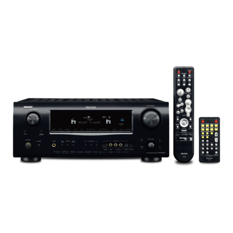
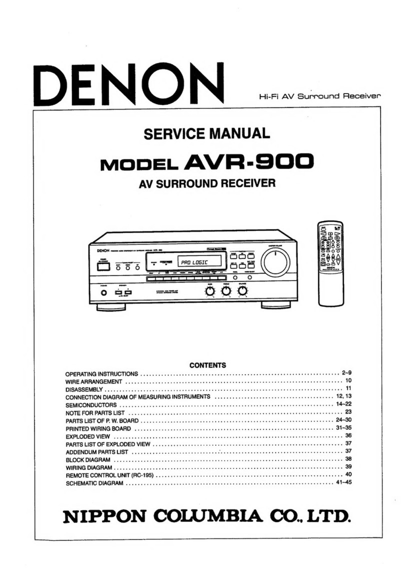
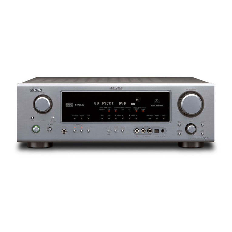
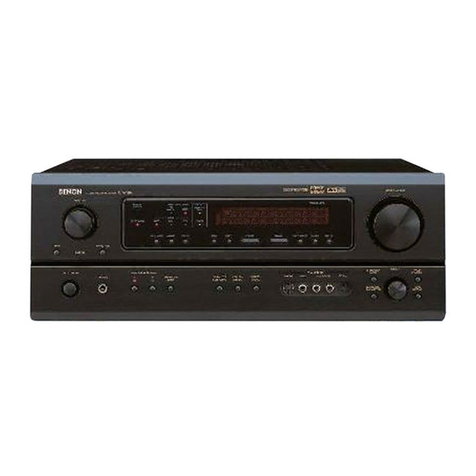
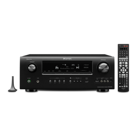
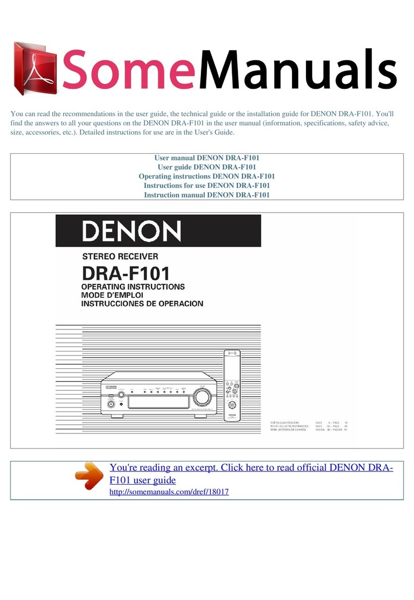
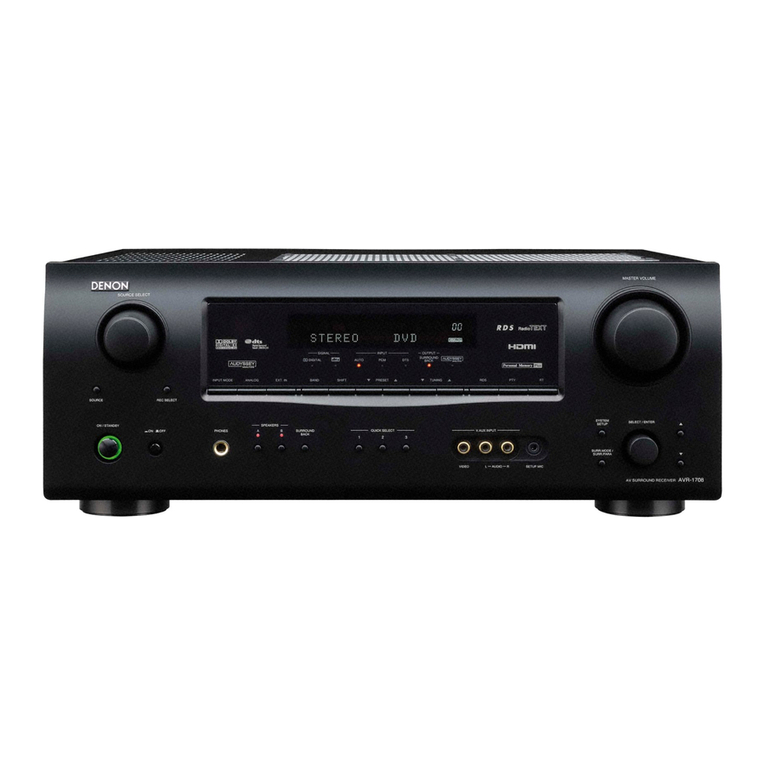
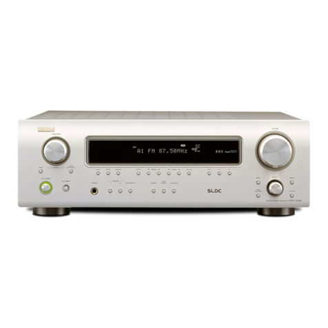
Denon DRA-29*5 User manual

FOR ENGLISH READERS PAGE 2, 03 ~ PAGE 013,080
FÜR DEUTSCHE LESER SEITE 2, 14 ~ SEITE 024,080
POUR LES LECTEURS FRANCAIS PAGE 2, 25 ~ PAGE 035,080
PER IL LETTORE ITALIANO PAGINA 2, 36 ~ PAGINA046,080
PARA LECTORES DE ESPAÑOL PAGINA 2, 47 ~ PAGINA057,080
VOOR NEDERLANDSTALIGE LEZERS PAGINA 2, 58 ~ PAGINA068,080
FOR SVENSKA LÄSARE SIDA 2, 69 ~ SIDA 079
VOLUME LEVEL
BDRA-295
PRECISION AUDIO COMPONENT / STEREO RECEIVER
PHONES SPEAKER
AB
TONE
CONTROL TREBLEBASS
UP
TUNING
MODE RDS PTY RTBAND MEMORY
SHIFT DOWN UP
PRESET
DOWN
MASTER VOLUME
UP
DOWN
DVD / VDP
AUX
CDR
CD
TUNER
TAPE
ON / STANDBY
REMOTE
SENSOR
DIMMER
AUTO PRESET
MEMORY STATUS TONE DEFEAT MUTING
RIGHTLEFT BALANCE
OFF ONPOWER
DISC SKIP +
RANDOM
CD
REPEAT
A / B REC
TAPE
MUTING
STATUS
DIMMER
TAPE
PRESET
SHIFT
TUNER
A
SPEAKER
B
MASTER VOL
AUX
CD CDR
DVD / VDP
REMOTE CONTROL UNIT RC-907
89
1
1
•
ª
•
ª
076
23
324
B
AM-FM STEREO RECEIVER
DRA-295
OPERATING INSTRUCTIONS
BEDIENUNGSANLEITUNG
MODE D’EMPLOI
ISTRUZIONI PER L’USO
INSTRUCCIONES DE OPERACION
GEBRUIKSAANWIJZING
BRUKSANVISNING

2
The lightning flash with arrowhead symbol, within an equilateral
triangle, is intended to alert the user to the presence of
uninsulated “dangerous voltage” within the product’s enclosure
that may be of sufficient magnitude to constitute a risk of electric
shock to persons.
The exclamation point within an equilateral triangle is intended to
alert the user to the presence of important operating and
maintenance (servicing) instructions in the literature accompanying
the appliance.
WARNING: TO REDUCE THE RISK OF FIRE OR ELECTRIC SHOCK, DO NOT
EXPOSE THIS APPLIANCE TO RAIN OR MOISTURE.
NOTE ON USE / HINWEISE ZUM GEBRAUCH
OBSERVATIONS RELATIVES A L’UTILISATION / NOTE SULL’USO
NOTAS SOBRE EL USO / ALVORENS TE GEBRUIKEN / OBSERVERA
• Avoid high temperatures.
Allow for sufficient heat dispersion
when installed on a rack.
• Vermeiden Sie hohe Temperaturen.
Beachten Sie, daß eine ausreichend
Luftzirkulation gewährleistet wird, wenn
das Gerät auf ein Regal gestellt wird.
• Eviter des températures élevées
Tenir compte d’une dispersion de
chaleur suffisante lors de l’installation
sur une étagère.
• Evitate di esporre l’unità a temperature
alte.
Assicuratevi che ci sia un’adeguata
dispersione del calore quando installate
l’unità in un mobile per componenti
audio.
• Evite altas temperaturas
Permite la suficiente dispersión del calor
cuando está instalado en la consola.
• Vermijd hoge temperaturen.
Zorg voor een degelijk hitteafvoer indien
het apparaat op een rek wordt geplaatst.
• Undvik höga temperaturer.
Se till att det finns möjlighet till god
värmeavledning vid montering i ett rack.
• Handle the power cord carefully.
Hold the plug when unplugging the
cord.
• Gehen Sie vorsichtig mit dem Netzkabel
um.
Halten Sie das Kabel am Stecker, wenn
Sie den Stecker herausziehen.
• Manipuler le cordon d’alimentation avec
précaution.
Tenir la prise lors du débranchement du
cordon.
• Manneggiate il filo di alimentazione con
cura.
Agite per la spina quando scollegate il
cavo dalla presa.
• Maneje el cordón de energía con
cuidado.
Sostenga el enchufe cuando
desconecte el cordón de energía.
• Hanteer het netsnoer voorzichtig.
Houd het snoer bij de stekker vast
wanneer deze moet worden aan- of
losgekoppeld.
• Hantera nätkabeln varsamt.
Håll i kabeln när den kopplas från el-
uttaget.
• Keep the set free from moisture, water,
and dust.
• Halten Sie das Gerät von Feuchtigkeit,
Wasser und Staub fern.
• Protéger l’appareil contre l’humidité,
l’eau et lapoussière.
• Tenete l’unità lontana dall’umidità,
dall’acqua e dalla polvere.
• Mantenga el equipo libre de humedad,
agua y polvo.
• Laat geen vochtigheid, water of stof in
het apparaat binnendringen.
• Utsätt inte apparaten för fukt, vatten
och damm.
• Unplug the power cord when not using
the set for long periods of time.
• Wenn das Gerät eine längere Zeit nicht
verwendet werden soll, trennen Sie das
Netzkabel vom Netzstecker.
• Débrancher le cordon d’alimentation
lorsque l’appareil n’est pas utilisé
pendant de longues périodes.
• Disinnestate il filo di alimentazione
quando avete l’intenzione di non usare il
filo di alimentazione per un lungo
periodo di tempo.
• Desconecte el cordón de energía
cuando no utilice el equipo por mucho
tiempo.
• Neem altijd het netsnoer uit het
stopkontakt wanneer het apparaat
gedurende een lange periode niet wordt
gebruikt.
• Koppla ur nätkabeln om apparaten inte
kommer att användas i lång tid.
• Do not obstruct the ventilation holes.
• Die Belüftungsöffnungen dürfen nicht
verdeckt werden.
• Ne pas obstruer les trous d’aération.
• Non coprite i fori di ventilazione.
• No obstruya los orificios de ventilación.
• De ventilatieopeningen mogen niet
worden beblokkeerd.
• Täpp inte till ventilationsöppningarna.
* (For sets with ventilation holes)
• Do not let foreign objects in the set.
• Keine fremden Gegenstände in das
Gerät kommen lassen.
• Ne pas laisser des objets étrangers dans
l’appareil.
• E’ importante che nessun oggetto è
inserito all’interno dell’unità.
• No deje objetos extraños dentro del
equipo.
• Laat geen vreemde voorwerpen in dit
apparaat vallen.
• Se till att främmande föremål inte
tränger in i apparaten.
• Do not let insecticides, benzene, and
thinner come in contact with the set.
• Lassen Sie das Gerät nicht mit
Insektiziden, Benzin oder
Verdünnungsmitteln in Berührung
kommen.
• Ne pas mettre en contact des
insecticides, du benzène et un diluant
avec l’appareil.
• Assicuratevvi che l’unità non venga in
contatto con insetticidi, benzolo o
solventi.
• No permita el contacto de insecticidas,
gasolina y diluyentes con el equipo.
• Laat geen insektenverdelgende
middelen, benzine of verfverdunner met
dit apparaat in kontakt komen.
• Se till att inte insektsmedel på
spraybruk, bensen och thinner kommer i
kontakt med apparatens hölje.
• Never disassemble or modify the set in
any way.
• Versuchen Sie niemals das Gerät
auseinander zu nehmen oder auf
jegliche Art zu verändern.
• Ne jamais démonter ou modifier
l’appareil d’une manière ou d’une autre.
• Non smontate mai, nè modificate l’unità
in nessun modo.
• Nunca desarme o modifique el equipo
de ninguna manera.
• Nooit dit apparaat demonteren of op
andere wijze modifiëren.
• Ta inte isär apparaten och försök inte
bygga om den.
ENGLISH DEUTSCH FRANCAIS ITALIANO ESPAÑOL NEDERLANDS SVENSKA
CAUTION
RISK OF ELECTRIC SHOCK
DO NOT OPEN
CAUTION: TO REDUCE THE RISK OF ELECTRIC
SHOCK, DO NOT REMOVE COVER (OR
BACK). NO USER-SERVICEABLE PARTS
INSIDE. REFER SERVICING TO QUALIFIED
SERVICE PERSONNEL.
•DECLARATION OF CONFORMITY
We declare under our sole responsibility that this
product, to which this declaration relates, is in
conformity with the following standards:
EN60065, EN55013, EN55020, EN61000-3-2 and
EN61000-3-3.
Following the provisions of 73/23/EEC, 89/336/EEC and
93/68/EEC Directive.
•ÜBEREINSTIMMUNGSERKLÄRUNG
Wir erklären unter unserer Verantwortung, daß dieses
Produkt, auf das sich diese Erklärung bezieht, den
folgenden Standards entspricht:
EN60065, EN55013, EN55020, EN61000-3-2 und
EN61000-3-3.
Entspricht den Verordnungen der Direktive 73/23/EEC,
89/336/EEC und 93/68/EEC.
•DECLARATION DE CONFORMITE
Nous déclarons sous notre seule responsabilité que
l’appareil, auquel se réfère cette déclaration, est
conforme aux standards suivants:
EN60065, EN55013, EN55020, EN61000-3-2 et
EN61000-3-3.
D’après les dispositions de la Directive 73/23/EEC,
89/336/EEC et 93/68/EEC.
•DICHIARAZIONE DI CONFORMITÀ
Dichiariamo con piena responsabilità che questo
prodotto, al quale la nostra dichiarazione si riferisce, è
conforme alle seguenti normative:
EN60065, EN55013, EN55020, EN61000-3-2 e
EN61000-3-3.
In conformità con le condizioni delle direttive 73/23/EEC,
89/336/EEC e 93/68/EEC.
QUESTO PRODOTTO E’ CONFORME
AL D.M. 28/08/95 N. 548
•DECLARACIÓN DE CONFORMIDAD
Declaramos bajo nuestra exclusiva responsabilidad que
este producto al que hace referencia esta declaración,
está conforme con los siguientes estándares:
EN60065, EN55013, EN55020, EN61000-3-2 y
EN61000-3-3.
Siguiendo las provisiones de las Directivas 73/23/EEC,
89/336/EEC y 93/68/EEC.
•EENVORMIGHEIDSVERKLARING
Wij verklaren uitsluitend op onze verantwoordelijkheid
dat dit produkt, waarop deze verklaring betrekking
heeft, in overeenstemming is met de volgende normen:
EN60065, EN55013, EN55020, EN61000-3-2 en
EN61000-3-3.
Volgens de bepalingen van de Richtlijnen 73/23/EEC,
89/336/EEC en 93/68/EEC.
•ÖVERENSSTÄMMELSESINTYG
Härmed intygas helt på eget ansvar att denna produkt,
vilken detta intyg avser, uppfyller följande standarder:
EN60065, EN55013, EN55020, EN61000-3-2 och
EN61000-3-3.
Enligt stadgarna i direktiv 73/23/EEC, 89/336/EEC och
93/68/EEC.
ENGLISH
3
2We greatly appreciate your purchase of the DRA-295.
2To be sure you take maximum advantage of all the features DRA-295 has to offer, read these
instructions carefully and use the set properly. Be sure to keep this manual for future reference
should any questions or problems arise.
“SERIAL NO.
PLEASE RECORD UNIT SERIAL NUMBER ATTACHED TO THE REAR OF
THE CABINET FOR FUTURE REFERENCE”
2INTRODUCTION
Thank you for choosing the DENON AM-FM Stereo receiver. This remarkable component has been engineered
to provide outstanding high fidelity reproduction of your favorite music sources.
As this product is provided with an immense array of features, we recommend that before you begin hookup and
operation that you review the contents of this manual before proceeding.
TABLE OF CONTENTS
2ACCESSORIES
Check that the following parts are included in addition to the main unit:
ert yu
B
zBefore Using .......................................................3
xCautions on Installation .......................................3
cCautions on Handling ..........................................3
vFeatures ..............................................................3
bPart Names and Functions ..................................4
nConnections ....................................................5, 6
mUsing the Remote Control Unit...........................7
,Operation ......................................................7 ~ 9
.Listening to the Radio.................................9 ~ 12
⁄0 Last Function Memory ......................................12
⁄1 Initialization of the Microprocessor ...................12
⁄2 Troubleshooting ................................................13
⁄3 Specifications ....................................................13
qOperating instructions……………………………1
wService station list ………………………………1
eRemote control unit (RC-907) …………………1
rR6P/AA batteries …………………………………2
tAM loop antenna …………………………………1
yFM indoor antenna ………………………………1
uFM antenna adapter .........................................1
1BEFORE USING
Pay attention to the following before using this unit:
•Moving the set
To prevent short circuits or damaged wires in the
connection cords, always unplug the power cord and
disconnect the connection cords between all other
audio components when moving the set.
•Before turning the power operation switch on
Check once again that all connections are proper and
that there are not problems with the connection cords.
Always set the power operation switch to the
standby position before connecting and disconnecting
connection cords.
•Store this instructions in a safe place.
After reading, store this instructions along with the
warranty in a safe place.
•Note that the illustrations in this instructions may
differ from the actual set for explanation purposes.
Noise or disturbance of the picture may be generated
if this unit or any other electronic equipment using
microprocessors is used near a tuner or TV.
If this happens, take the following steps:
• Install this unit as far as possible from the tuner or
TV.
• Set the antenna wires from the tuner or TV away from
this unit’s power cord and input/output connection
cords.
• Noise or disturbance tends to occur particularly when
using indoor antennas or 300 Ω/ohms feeder wires.
We recommend using outdoor antennas and 75
Ω/ohms coaxial cables.
For heat dispersal, leave at least 10 cm of space
between the top, back and sides of this unit and the
wall or other components.
•Switching the input function when input jacks are
not connected
A clicking noise may be produced if the input function
is switched when nothing is connected to the input
jacks. If this happens, either turn down the MASTER
VOLUME control or connect components to the input
jacks.
•Muting of HEADPHONE jack and SPEAKER
terminals
The HEADPHONE jack and SPEAKER terminals
include a muting circuit. Because of this, the output
signals are greatly reduced for several seconds after
the power operation switch is turned on or input
function, surround mode or any other set-up is
changed.
If the volume is turned up during this time, the output
will be very high after the muting circuit stops
functioning. Always wait until the muting circuit turns
off before adjusting the volume.
•Whenever the power operation switch is in the
£OFF or STANDBY state, the apparatus is still
connected on some AC line voltages.
Please be sure to unplug the cord when you leave
home for, say, a vacation.
1. Powerful, Versatile Amplifier
High-Quality Power Amplifier:
High-speed, high-power transistors employed in a
rational circuit configuration reflect DENON’S
advanced amplifier technology and ensure a very
hefty, clean power output.
2. Signal Level Divided Construction (SLDC)
The circuits handling low-level and high-level signals
have been divided into separate blocks to ensure
that influences from these signals on each other
are held to an absolute minimum. This chassis
design in this unit is called the Signal Level Divided
Construction (SLDC). Signals for output are cleaner
than before, allowing them to be reproduced with
even greater fidelity and clarity.
3. Remote Control Functions
The Remote Control (RC-907) commands not only
the receiver but can also operate the main
functions of a DENON CD player and a cassette
deck.
2CAUTIONS ON INSTALLATION
3CAUTIONS ON HANDLING
4FEATURES
10 cm or more
10 cm or more
wall
B

ENGLISH
4
OFF ONPOWER
DISC SKIP +
RANDOM
CD
REPEAT
A / B REC
TAPE
MUTING
STATUS
DIMMER
TAPE
PRESET
SHIFT
TUNER
A
SPEAKER
B
MASTER VOL
AUX
CD CDR
DVD / VDP
REMOTE CONTROL UNIT RC-907
89
1
1
•
ª
•
ª
076
23
324
B
5PART NAMES AND FUNCTIONS
Front Panel
• For details on the functions of these parts, refer to the pages given in parentheses ( ).
VOLUME LEVEL
BDRA-295
PRECISION AUDIO COMPONENT / STEREO RECEIVER
PHONES
¢ ON / STANDBY
£ OFF
SPEAKER
AB
TONE
CONTROL TREBLEBASS
UP
TUNING
MODEBAND MEMORY
RDS
PTY RT
SHIFT DOWN UP
PRESET
DOWN
MASTER VOLUME
UP
DOWN
DVD / VDP
AUX
CDR
CD
TUNER
TAPE
ON / STANDBY
REMOTE
SENSOR
DIMMER
AUTO PREST
MEMORY STATUS TONE DEFEAT MUTING
RIGHTLEFT BALANCE
q w re
!4
!5!6!8 !7
o!2it y u
!3!9
!0 !1
qPower operation switch ..........................(7, 9, 12)
wHeadphones jack (PHONES) .............................(8)
eSPEAKER A/B buttons ............................(7, 8, 12)
rAUTO PRESET MEMORY button .....................(9)
tDIMMER button................................................(9)
ySTATUS button .................................................(9)
uTONE DEFEAT button.......................................(8)
iMUTING button.................................................(8)
oRDS button......................................................(11)
!0 PTY button ......................................................(11)
!1 RT button ........................................................(12)
!2 TONE and BALANCE buttons ...........................(8)
!3 MASTER VOLUME control ...............................(8)
!4 MASTER VOLUME indicator
(VOLUME LEVEL) .............................................(8)
!5 Display
!6 Tuning/Preset memory
selector buttons........................................(9 ~ 12)
!7 Power indicator .................................................(7)
!8 Remote control sensor (REMOTE SENSOR) ....(7)
!9 Input source selector buttons .........(8, 10, 11, 12)
Remote control unit
• For details on the functions of these parts, refer to the pages given in parentheses ( ).
• DENON remote-controllable CD player and tape deck (TAPE) can be controlled using this unit's remote
control unit (RC-907).
STATUS button .......................(9)
Remote control signal
transmitter ..............................(7)
POWER buttons......................(7)
VOLUME control
buttons....................................(8)
SPEAKER (A/B) buttons ......(7, 8)
DIMMER button......................(9)
Preset memory selector
buttons..................................(10)
MUTING button ......................(8)
Input source selector
buttons....................................(8)
CD controlled buttons
8, 9:Auto search
(reverse and forward)
1:Play
2:Stop
3:Pause
RANDOM :RANDOM
REPEAT : REPEAT
DISC SKIP+ :Disc selection
(CD changer only)
TAPE (tape deck) controlled buttons
0, 1:
Play (reverse and forward)
6, 7:
Rewind and Fast-forward
2:Stop
3:Pause
4REC :REC
A / B :Tape A/B selection

ENGLISH
5
DVD/ VDP
TAPE
TAPE
CDR
AUX
CDR
IN
OUT
CD
RL
RL
AUDIO
ANTENNA TERMINALS
SPEAKER SYSTEMS
SPEAKER IMPEDANCE
A OR B / 4 16
A + B / 8 16
R L R L
AB
FM
COAX.
75
AM
LOOP
ANT.
AC OUTLET
AC 230V 50Hz
SWITCHED
100W MAX.
RINPUTOUTPUT
LRL
L
R
L
R
AUDIO IN
AUDIO OUT
AUDIO OUT
AUDIO OUT
AUDIO IN
RINPUTOUTPUT
LRL
L
R
L
R
R
OUTPUT
L
RL
R
L
DIGITALAUDIODIGITALAUDIO
L
R
L
R
L
R
L
R
B
• Do not plug in the power cord until all
connections have been completed.
• Be sure to connect the left and right channels
properly (left with left, right with right).
• Insert the plugs securely. Incomplete
connections will result in the generation of noise.
•Use the AC OUTLET for audio equipment
only. Do not use them for hair driers, etc.
• Note that binding pin plug cords together with
power cords or placing them near a power
transformer will result in generating hum or other
noise.
• Noise or humming may be generated if a
connected component is used independently
without turning the power of this unit on. If this
happens, turn on the power of the this unit.
Connecting the audio components
CD player
Connecting a tape deck
Connections for recording:
Connect the tape deck’s recording input jacks (LINE IN
or REC) to this unit’s tape recording (OUT) jacks using
pin plug cords.
Connections for playback:
Connect the tape deck’s playback output jacks (LINE
OUT or PB) to this unit’s tape playback (IN) jacks using
pin plug cords.
6CONNECTIONS
Connecting a CD player
Connect the CD player’s output jacks to this unit’s
CD jacks using pin plug cords.
Tape deck
AC 230 V, 50 Hz
AC CORD
Connecting the AC OUTLET
AC OUTLET
• SWITCHED (capacity – 100 W)
The power to these outlets is turned on and off in conjunction
with the power operation switch on the main unit, and when the
power is switched between on and standby from the remote
control unit.
No power is supplied from this outlet when this unit’s power is
at standby. Never connect equipment whose capacity is above
100 W.
NOTE:
Only use the AC OUTLET for audio equipment. Never use them
for hair driers, TVs or other electrical appliances.
1
4
23
DVD/ VDP
TAPE
TAPE
CDR
AUX
CDR
IN
OUT
CD
RL
RL
AUDIO
ANTENNA TERMINALS
FM
COAX.
75
AM
LOOP
ANT.
Connecting the antenna terminals
DIRECTION OF
BROADCASTING
STATION FM ANTENNA
75 Ω/ohms
COAXIAL
CABLE
FM INDOOR ANTENNA
(An Accessory)
AM LOOP
ANTENNA
(An Accessory)
AM OUTDOOR
ANTENNA
GROUND
NOTES:
•Do not connect two FM antennas simultaneously.
•Even if an external AM antenna is used, do not
disconnect the AM loop antenna.
•Make sure AM loop antenna lead terminals do
not touch metal parts of the panel.
Connection of AM antennas
1. Push the lever. 2. Insert the
conductor.
3. Return the lever.
AM loop antenna assembly
Connect to the AM
antenna terminals.
Bend in the reverse
direction.
Remove the vinyl tie
and take out the
connection line.
a. With the antenna
on top any stable
surface.
b. With the antenna
attached to a wall.
Installation hole Mount on wall, etc.
Mount
FEEDER
CABLE
FM ANTENNA
ADAPTER
(An Accessory)
FM ANTENNA
ADAPTER
(An Accessory)
300 Ω/ohms
300 Ω/ohms
TERMINAL
14mm
9mm
14mm
19mm
5mm
5mm
5C-2V3C-2V
75 Ω/ohms COAXIAL CABLE
Open the Cover
ANTENNA ADAPTER
REMOVE
CLAMP
CLAMP
CLAMP
SHUT
PULL
PULL
FM antenna adapter assembly
CD recorder

ENGLISH
6
Speaker system connections
•Connect the speaker terminals with the speakers
making sure that like polarities are matched (<with
<, >with >). Mismatching of polarities will result
in weak central sound, unclear orientation of the
various instruments, and the sense of direction of the
stereo being impaired.
•When making connections, take care that none of
the individual conductors of the speaker cord come
in contact with adjacent terminals, with other speaker
cord conductors, or with the rear panel.
Speaker Impedance
•When speaker systems A and B are use separately,
speakers with an impedance of 4 to 16 Ω/ohms can
be connected for use as speakers.
•Be careful when using two pairs of speakers (A + B)
at the same time, since use of speakers with an
impedance of 8 to 16 Ω/ohms.
•The protector circuit may be activated if the set is
played for long periods of time at high volumes when
speakers with an impedance lower than the specified
impedance are connected.
1. Loosen by turning
counterclockwise.
2. Insert the cord. 3. Tighten by turning
clockwise.
NOTE:
NEVER touch the speaker terminals when the
power is on.
Doing so could result in electric shocks.
System A
SPEAKER SYSTEMS SPEAKER SYSTEMS
•Precautions when connecting speakers
If a speaker is placed near a TV or video
monitor, the colors on the screen may be
disturbed by the speaker’s magnetism. If
this should happen, move the speaker
away to a position where it does not have
this effect.
Connecting the speaker cords
DVD/ VDP
TAPE
TAPE
CDR
AUX
CDR
IN
OUT
CD
RL
RL
AUDIO
ANTENNA TERMINALS
SPEAKER SYSTEMS
SPEAKER IMPEDANCE
A OR B / 4 16
A + B / 8 16
R L R L
AB
FM
COAX.
75
AM
LOOP
ANT.
(L) (R)(L) (R)
System B
Protector circuit
•This unit is equipped with a high-speed protection circuit. This circuit protects the internal circuitry
from damage due to large currents flowing if the speaker jacks are not completely connected or if an
output is generated by a short circuit.
In such a case, the protection circuit will operate to cut off the output to the speakers. Should this
happen, turn the power off and check the speaker connections. Then turn the power on again. After
muting for several seconds, the receiver should be operating normally.
If the protection circuit is activated again even though there are no problems with the wiring or the
ventilation around the unit, switch off the power and contact a DENON service center.
Note on speaker impedance
•The protector circuit may be activated if the set is played for long periods of time at high volumes
when speakers with an impedance lower than the specified impedance are connected. If the
protector circuit is activated, the speaker output is cut off. Turn off the set’s power, wait for the set
to cool down, improve the ventilation around the set, then turn the power back on.

ENGLISH
7
Following the procedure outlined below, insert the batteries before using the remote control unit.
Point the remote control unit at the remote control
sensor as shown on the diagram at the left.
NOTES:
•The remote control unit can be used from a straight
distance of approximately 7 meters, but this distance
will shorten or operation will become difficult if there
are obstacles between the remote control unit and
the remote control sensor, if the remote control
sensor is exposed to direct sunlight or other strong
light, or if operated from an angle.
•Neon signs or other devices emitting pulse-type noise
nearby may result in malfunction, so keep the set as
far away from such devices as possible.
B
B
Approx. 7 m
qPress as shown by the arrow
and slide off.
wInsert the R6P/AA batteries properly,
as shown on the diagram.
eClose the lid.
NOTES:
•Use only R6P/AA batteries for replacement.
•Be sure the polarities are correct. (See the illustration inside the battery compartment.)
•Remove the batteries if the remote control transmitter will not be used for an extended period of time.
•If batteries leak, dispose of them immediately. Avoid touching the leaked material or letting it come in contact
with clothing, etc. Clean the battery compartment thoroughly before installing new batteries.
•Have replacement batteries on hand so that the old batteries can be replaced as quickly as possible when the
time comes.
•Even if less than a year has passed, replace the batteries with new ones if the set does not operate even when
the remote control unit is operated nearby the set. (The included battery is only for verifying operation.
Replace it with a new battery as soon as possible.)
30°
7USING THE REMOTE CONTROL UNIT
Range of operation of the remote control unit
Inserting the batteries
30°
Preparations:
Check that all connections are proper.
Turn on the power.
Press the power operation switch (button).
OFF ONPOWER
SPEAKER
AB
B
OFF ONPOWER
DISC SKIP +
RANDOM
CD
REPEAT
A / B REC
TAPE
MUTING
STATUS
DIMMER
TAPE
PRESET
SHIFT
TUNER
A
SPEAKER
B
MASTER VOL
AUX
CD CDR
DVD / VDP
REMOTE CONTROL UNIT RC-907
89
1
1
•
ª
•
ª
076
23
324
B
1 11 2
1
2
8OPERATION
Before operating
1
Select the speakers.
Press the SPEAKER A or B button turn the speaker
on.
2
•¢ON/STANDBY
The power turns on and power indicator is lit.
Several seconds are required from the time
the power operation switch is set to the “¢
ON/STANDBY”position until sound is output.
This is due to the built-in muting circuit that
prevents noise when the power switch is turned
on and off.
Set the power operation switch to this position
to turn the power on and off from the included
remote control unit.
•£OFF
The power turns off and power indicator is off.
In this position, the power cannot be turned on
and off from the remote control unit.
(Main unit) (Remote control unit)
(Main unit)
A
SPEAKER
B
(Remote control unit)

ENGLISH
8
Press the button for the program source to be
played.
EX : CD
1
CD
CD
(Main unit) (Remote control unit)
Start playback on the selected component.
•
For operating instructions, refer to the component’s
manual.
2
Adjust the volume.
3
MASTER VOLUME
MASTER VOL
•
ª
(Main unit) (Remote control unit)
The volume level is
displayed on the master
volume level display.
The volume can be adjusted within the range
of –60 to 0 to 18 dB, in steps of 1 dB. However,
when the channel level is set as described on
“Adjusting the BALANCE control”, if the
volume for any channel is set at +1 dB or
greater, the volume cannot be adjusted up to
18 dB. (In this case the maximum volume
adjustment range is “18 dB —(Maximum
value of channel level)”.)
Adjusting the sound quality (TONE CONTROL)
1Select the BASS or TREBLE whose you want to
adjust.
2
B
1 123
3
Press the select button to
adjust the level.
•To increase the bass or treble:
Press the select UP button.
(The bass or treble sound
can be increased to up to
+10 dB in steps of 2 dB.)
•To decrease the bass or treble:
Press the select DOWN button. (The treble
sound can be decreased to up to -10 dB in
steps of 2 dB.)
TREBLE
BASS
TONE
CONTROL
BALANCE
UP
DOWN
If you do not want the bass and treble to be
adjusted, turn on the tone defeat mode.
•The signals do not pass through the bass and
treble adjustment circuits providing higher
quality sound.
TONE DEFEAT
Adjusting the BALANCE control
1Select the channel whose level you want to
adjust.
2
B
1 12
(L channel) (R channel)
Adjust the level of the selected
channel.
The volume can be adjusted
between -12 dB and +12 dB in
units of 1 dB.
If the volume is set to 7 dB or greater with
the MASTER VOLUME control, the
maximum channel level is the maximum
level of the MASTER VOLUME control 18 dB
minus the level at which the MASTER
VOLUME control is set.
LEFT
RIGHT
TONE
CONTROL
BALANCE
UP
DOWN
B
1 2
1Connect the headphones to the
PHONES jack of the front panel.
PHONES
2Press the SPEAKER A or B button turn the
speaker off.
SPEAKER
AB
(Main unit) (Remote control unit)
Listening over headphones
MUTING
STATUS
DIMMER
TAPE
PRESET
SHIFT
TUNER
A
SPEAKER
B
MASTER VOL
AUX
CD CDR
DVD / VDP
•
ª
•
ª
2
A
SPEAKER
B
NOTE:
To prevent hearing loss, do not raise the volume
level excessively when using headphones.
1
MUTING
STATUS
DIMMER
PRESET
A
SPEAKER
B
MASTER VOL
REMOTE CONTROL UNIT RC-907
•
ª
•
ª
B
1
Turning the sound off temporarily (muting)
B
1
Use this to turn off the audio output temporarily.
Press the MUTING button.
Cancelling MUTING mode.
•Press the MUTING button again.
•Muting will also be cancelled when MASTER
VOL is adjusted up or down.
MUTING
(Main unit) (Remote control unit)
MUTING
Playing the input source
B
1 33
A / B REC
TAPE
MUTING
STATUS
DIMMER
TAPE
PRESET
SHIFT
TUNER
A
SPEAKER
B
MASTER VOL
AUX
CD CDR
DVD / VDP
REMOTE CONTROL UNIT RC-709
1
•
ª
•
ª
076
324
B
1
3
(Main unit)
•Caution:
Switching off the power of the unit will cancel the settings.

ENGLISH
9
1
Recording the program source (recording the source currently being monitored)
1Follow step 1 to 3 under “Playing the input source”.2Start recording on the tape deck or CD recorder.
For instructions, refer to the component’s operating
instructions.
The signals of the source selected with the function selector button are output simultaneously to the TAPE and
CDR REC OUT jacks. If a total of two tape decks are connected and set to the recording mode, the same
source can be recorded simultaneously on every decks.
Simultaneous recording
NOTES:
•The AUDIO IN’s signal selected with the function selector button are output to the TAPE and CDR AUDIO
OUT jacks.
Checking the currently playing program source, etc.
Front panel display
•
Descriptions of the unit’s operations are also
displayed on the front panel display. In
addition, the display can be switched to check
the unit’s operating status while playing a
source by pressing the STATUS button.
MUTING
STATUS
DIMMER
TAPE
PRESET
SHIFT
TUNER
A
SPEAKER
B
MASTER VOL
AUX
CD CDR
DVD / VDP
REMOTE CONTROL UNIT RC-907
1
•
ª
•
ª
076
B
1
2
B
12
STATUS
(Main unit)
STATUS
(Remote control unit)
2Using the dimmer function
•Use this to change the brightness of the
display.
The display brightness changes in four steps
(bright, medium, dim and off) by pressing the
main unit’s DIMMER button repeatedly.
DIMMER
(Main unit)
DIMMER
(Remote control unit)
The brightness changes in 3 steps each time the
button is pressed, and finally the display turns off.
9LISTENING TO THE RADIO
Auto preset memory
This unit is equipped with a function for automatically searching for FM broadcast stations and storing them in the
preset memory.
1When the main unit’s power operation switch
turn on while pressing the set’s MEMORY button
the unit automatically begins searching for FM
broadcast stations.
AUTO PRESET
2When the first FM broadcast station is found, that
station is stored in the preset memory at channel
A1. Subsequent stations are automatically stored
in order at preset channels A2 to A8, B1 to B8, C1
to C8, D1 to D8 and E1 to E8, for a maximum of
40 stations.
3Channel A1 is tuned in after the auto preset
memory operation is completed.
NOTES:
•If an FM station cannot be preset automatically
due to poor reception, use the “Manual tuning”
operation to tune in the station, then preset it
using the manual “Preset memory”operation.
•To interrupt this function, press the power
operation switch.
B
131, 2
2DEFAULT VALUE
AUTO TUNER PRESETS
A1 ~ A8 87.5/89.1/98.1/108/90.1/90.1/90.1/90.1 MHz
B1 ~ B8 522/603/999/1404/1611 kHz/90.1/90.1/90.1 MHz
C1 ~ C8 90.1 MHz
D1 ~ D8 90.1 MHz
E1 ~ E8 90.1 MHz
(Main unit)

ENGLISH
10
Auto tuning
1Set the input function to “TUNER”.
TUNER
2Watching the display, press the BAND button to
select the desired band (AM or FM).
BAND
3Press the MODE button to set the auto tuning
mode.
Lit
4Press the TUNING UP or DOWN button.
•Automatic searching begins, then stops when
a station is tuned in.
NOTE:
•When in the auto tuning mode on the FM band, the
“STEREO”indicator lights on the display when a
stereo broadcast is tuned in. At open frequencies,
the noise is muted and the “TUNED”and “STEREO”
indicators turn off.
B
4321
Manual tuning
1Set the input function to “TUNER”.3Press the MODE button to set the manual tuning
mode.
Check that the display’s “AUTO”indicator turns
off.
2Watching the display, press the BAND button to
select the desired band (AM or FM).
Press the TUNING UP or DOWN button to tune
in the desired station.
The frequency changes continuously when the
button is held in.
4
NOTE:
•When the manual tuning mode is set, FM stereo broadcasts are received in monaural and the “STEREO”indicator
turns off.
(Main unit)
(Main unit)
(Main unit)
(Main unit)
Preset stations
B
3 1, 42
MUTING
STATUS
DIMMER
TAPE
PRESET
SHIFT
TUNER
A
SPEAKER
B
MASTER VOL
AUX
CD CDR
DVD / VDP
REMOTE CONTROL UNIT RC-907
•
ª
•
ª
B
2
3
Preparations:
Use the “Auto tuning”or “Manual tuning”operation
to tune in the station to be preset in the memory.
1Press the MEMORY button.
MEMORY
(Main unit)
NOTE: Please make sure the “AUDIO”position
of the slide switch on the remote control
unit.
2Press the SHIFT button and select the desired
memory block (A to E).
SHIFT
SHIFT
(Main unit) (Remote control unit)
3Press the PRESET UP or DOWN button to select
the desired preset channel (1 to 8).
PRESET
•
ª
(Main unit) (Remote control unit)
4Press the MEMORY button again to store the
station in the preset memory.
MEMORY
(Main unit)
To preset other channels, repeat steps 1 to 4.
A total of 40 broadcast stations can be preset –8
stations (channels 1 to 8) in each of blocks A to E.
Recalling preset stations
B
21
MUTING
STATUS
DIMMER
TAPE
PRESET
SHIFT
TUNER
A
SPEAKER
B
MASTER VOL
AUX
CD CDR
DVD / VDP
REMOTE CONTROL UNIT RC-907
•
ª
•
ª
B
1
2
1Watching the display, press the SHIFT button to
select the preset memory block.
SHIFT
SHIFT
(Main unit) (Remote control unit)
2Watching the display, press the PRESET UP or
DOWN button to select the desired preset channel.
PRESET
•
ª
(Main unit) (Remote control unit)

ENGLISH
11
RDS (Radio Data System)
RDS (works only on the FM band) is a broadcasting service which allows station to send additional information
along with the regular radio program signal.
The following three types of RDS information can be received on this unit:
2Program Type (PTY)
PTY identifies the type of RDS program.
The program types and their displays are as follows:
NEWS
AFFAIRS
INFO
SPORT
EDUCATE
ROCK M
EASY M
LIGHT M
CLASSICS
OTHER M
PHONE IN
TRAVEL
LEISURE
JAZZ
COUNTRY
DRAMA
CULTURE
SCIENCE
VARIED
POP M
WEATHER
FINANCE
CHILDREN
SOCIAL
RELIGION
NATION M
OLDIES
FOLK M
DOCUMENT
News Rock Music Phone In
Travel
Leisure
Jazz Music
Country Music
Easy Listening
Music
Light Classical
Serious
Classical
Other Music
Current Affairs
Information
Sports
Education
2Traffic Program (TP)
TP identifies programs that carry traffic announcements.
This allows you to easily find out the latest traffic conditions in your area before you leaving home.
2Radio Text (RT)
RT allows the RDS station to send text messages that appear on the display.
NOTE: The operations described below using the RDS, PTY and RT buttons will not function in areas in which
there are no RDS broadcasts.
RDS search
Use this function to automatically tune to FM stations that provide RDS service.
B
2
13
Press the RDS button until “RDS
SEARCH”appears on the display.
Press the PRESET UP or DOWN
button to automatically begin the
RDS search operation. When a broadcast station is found, that station's
name appears on the display.
To continue searching, repeat step 3.
If no other RDS station is found when all the
frequencies are searched, “NO RDS”is displayed.
1Set the input function to “TUNER”.
TUNER
(Main unit)
2
(Main unit)
3
(Main unit)
4
5
If no RDS stations is found with above operation,
all the reception band are searched.
PTY search
Use this function to find RDS stations broadcasting a designated program type (PTY).
For a description of each program type, refer to “Program Type (PTY)”.
Set the input function to “TUNER”.
B
2 3
1 4
Press the RDS button until “PTY
SEARCH”appears on the display.
Watching the display, press the PTY
button to call out the desired program
type.
Press the PRESET UP or DOWN
button to automatically begin the
PTY search operation.
The station name is displayed on the display after
searching stops.
To continue searching, repeat step 4.
If no other station broadcasting the designated
program type is found when all the frequencies
are searched, “NO PROGRAMME”is displayed.
1
TUNER
(Main unit)
2
(Main unit)
3
(Main unit)
4
If there is no station broadcasting the designated
program type with above operation, all the reception
bands are searched.
5
6
(Main unit)
Drama Weather National Music
Oldies Music
Folk Music
Documentary
Finance
Children's
programmes
Social Affairs
Religion
Culture
Science
Varied
Pop Music

ENGLISH
12
TP search
Use this function to find RDS stations broadcasting traffic program (TP stations)
Set the input function to “TUNER”.
B
2
13
Press the RDS button until “TP
SEARCH”appears on the display.
Press the PRESET UP or DOWN
button TP search begins.
If no TP station is found with above operation, all
the reception bands are searched.
The station name is displayed on the display after
searching stops.
To continue searching, repeat step 3.
If no other TP station is found when all the
frequencies are searched, “NO PROGRAMME”
is displayed.
RT (Radio Text)
“RT”appears on the display when radio text data is
received.
When the RT button is pressed while receiving an RDS
broadcast station, the text data broadcast from the
station is displayed. To turn the display off, press the
RT button again. If no text data is being broadcast, “NO
TEXT DATA”is displayed.
B
”RT”
1
TUNER
(Main unit)
2
(Main unit)
3
4
5
(Main unit)
10 LAST FUNCTION MEMORY
•This unit is equipped with a last function memory which stores the input and output setting conditions as they
were immediately before the power is switched off.
•The unit is also equipped with a back-up memory. This function provides approximately one week of memory
storage when the main unit’s power operation switch is off and with the power cord disconnected.
11 INITIALIZATION OF THE MICROPROCESSOR
When the indication of the display is not normal or when the operation of the unit does not shows the reasonable
result, the initialization of the microprocessor is required by the following procedure.
B
21, 2
1Switch off the unit using the main unit’s power
operation switch.
2Hold the following SPEAKER A button and B
button, and turn the main unit’s power operation
switch on.
3Check that the entire display is flashing with an
interval of about 1 second, and release your fingers
from the 2 buttons and the microprocessor will
be initialized.
NOTES:
•If step 3 does not work, start over from step 1.
•If the microprocessor has been reset, all the
button settings are reset to the default values
(the values set upon shipment from the factory).

ENGLISH
13
12 TROUBLESHOOTING
If a problem should arise,first check the following.
1. Are the connections correct ?
2. Have you operated the receiver according to the Operating Instructions ?
3. Are the speakers, turntable and other components operating property ?
If this unit is not operating properly, check the items listed in the table below. Should the problem persist, there
may be a malfunction.
Disconnect the power immediately and contact your store of purchase.
Symptom Cause Measures Page
DISPLAY not lit and sound
not produced when power
operation switch set to on.
•Power cord not plugged in securely. •Check the insertion of the power cord
plug.
•Turn the power on with the remote
control unit after turning the power
operation switch on.
5
7
DISPLAY lit but sound not
produced.
•Speaker cords not securely connected.
•Improper position of the audio function
button.
•Volume control set to minimum.
•MUTING is on.
•Connect securely.
•Set to a suitable position.
•Turn volume up to suitable level.
•Switch off MUTING.
6
8
8
8
DISPLAY not displayed and
the power indicator flashes
at a high rate.
•Speaker terminals are short-circuited.
•Block the ventilation holes of the set.
•The unit is operating at continuous high
power conditions and/or inadequate
ventilation.
•Switch power off, connect speakers
properly, then switch power back on.
•Turn off the set’s power, then ventilate
it well to cool it down.
Once the set is cooled down, turn the
power back on.
•Turn off the set’s power, then ventilate
it well to cool it down.
Once the set is cooled down, turn the
power back on.
6
3
3
Sound produced only from
one channel.
•Incomplete connection of speaker cords.
•Incomplete connection of input/output
cords.
•Connect securely.
•Connect securely. 6
5 ~ 6
Positions of instruments
reversed during stereo
playback.
•Reverse connections of left and right
speakers or left and right input/output
cords.
•Check left and right connections. 5 ~ 6
This unit does not operate
properly when remote
control unit is used.
•Batteries dead.
•Remote control unit too far from this
unit.
•Obstacle between this unit and remote
control unit.
•Different button is being pressed.
•<and >ends of battery inserted in
reverse.
•Replace with new batteries.
•Move closer.
•Remove obstacle.
•Press the proper button.
•Insert batteries properly.
7
7
7
—
7
Common problems arising when listening to the
CD, records, tapes, and FM broadcasts, etc.
Remote control unit.
2Amplifier section
Rated output: 50 W + 50 W (8 Ω/ohms, 20 Hz ~ 20 kHz with 0.08 % T.H.D.)
70 W + 70 W (4 Ω/ohms, 1 kHz with 0.7 % T.H.D.)
Output terminals: A or B 4 to 16 Ω/ohms
A + B 8 to 16 Ω/ohms or more
Input sensitivity/input impedance: 200 mV/47 kΩ/kohms
Frequency response: 10 Hz ~ 50 kHz: ±1.5 dB
S/N ratio: 98 dB (IHF-A weighted)
Total harmonic distortion: 0.009% (-3dB at rated output, 8Ω/ohms) (1kHz)
2Tuner section
[FM] (note:
µ
V at 75
Ω
/ohms, 0 dBf = 1 x 10–15 W) [AM]
Receiving range: 87.50 MHz ~ 108.00 MHz 522 kHz ~ 1611 kHz
Usable sensitivity: 1.4 µV (14.2 dBf) 18 µV
50 dB quieting sensitivity: MONO 2.8
µ
V (20.2 dBf)
STEREO 23
µ
V (38.5 dBf)
S/N ratio: MONO 80 dB (IHF-A weighted)
STEREO 75 dB (IHF-A weighted)
Total harmonic distortion: MONO 0.15 % (1 kHz)
STEREO 0.3 % (1 kHz)
2General
Power supply: AC 230 V, 50 Hz
Power consumption: 150 W
Maximum external dimensions: 434 (W) x 147 (H) x 417 (D) mm
Mass: 9.2 kg
2Remote control unit (RC-907)
Batteries: R6P/AA Type (two batteries)
External dimensions: 50 (W) x 179 (H) x 22 (D) mm
Mass: 125 g (including batteries)
For purposes of improvement, specifications and design are subject to change without notice.
13 SPECIFICATIONS

DEUTSCH
14
Wand
B
2Wir freuen uns, daß Sie sich für den Kauf des DRA-295 entschieden haben.
2Um die maximale Nutzung der Vorteile der Funktionen sicherzustellen, die der DRA-295 zu
bieten hat, lesen Sie die hier enthaltenen Hinweise mit Bedacht und benutzen Sie das Gerät
entsprechend. Bewahren Sie dieses Handbuch gut auf, um bei Fragen oder Problemen darauf
zurückgreifen zu können.
“SERIENNR.
NOTIEREN SIE BITTE HIER DIE AUF DER RÜCKSEITE DES GERÄTES
ANGEBRACHTE SERIENNUMMER FÜR DEN SPÄTEREN ZUGRIFF”
2EINFÜHRUNG
Wir danken Ihnen für den Kauf dieses DENON AM-FM Stereo-Receivers. Diese bemerkenswerte Komponente
wurde für eine fantastisch hochqualitative Wiedergabe Ihrer Lieblings-Musikquellen entwickelt.
Da dieses Gerät mit einer Vielzahl von Funktionen ausgestattet ist, sollten Sie vor der Aufstellung und
Inbetriebnahme unbedingt einen Blick auf das Inhaltsverzeichnis dieser Betriebsanleitung werfen.
INHALT
2ZUBEHÖR
Prüfen Sie bitte, ob folgende Teile als Zubehör zum Gerät mitgeliefert wurden:
ert yu
B
qBedienungsanweisung ……………………………1
wServicewerkstätten ………………………………1
eFernbedienung (RC-907) …………………………1
rBatterien (R6P/AA) …………………………………2
tMW-Rahmenantenne ……………………………1
yUKW-Raumantenne………………………………1
uUKW-Antennenadapter …………………………1
1VOR DER BENUTZUNG
Beachten Sie bitte vor der Benutzung des Gerätes nachfolgende Hinweise:
•Umstellen des Gerätes
Zur Vermeidung von Kurzschlüssen oder Kabelbrüchen in
den Verbindungskabeln, ziehen Sie das Netzkabel und die
Verbindungskabel zu allen Audio-Geräten ab, bevor Sie das
Gerät auf einen anderen Platz umstellen.
•Bevor Sie das Netz Betrieb Schalter
Prüfen Sie nochmals, ob alle Anschlüsse in Ordnung sind
und keine Probleme mit den Verbindungskabeln vorhanden
sind. Schalten Sie den Netz Betrieb Schalter stets auf die
Standby-Position bevor Sie Verbindungskabel abziehen oder
anschließen.
•Bewahren Sie diese Bedienungsanweisungen an einem
sicheren Platz auf
Nachdem Sie diese Bedienungsanleitung gelesen haben,
bewahren Sie diese zusammen mit den Garantieunterlagen
an einem sicheren Ort auf.
•Beachten Sie, daß die Abbildungen in diesem Bedie-
nungshandbuch zur besseren Darstellung von der Wir-
klichkeit abweichen können.
Wenn dieses Gerät oder irgendwelche andere Geräte, die
Mikroprozessoren enthalten in der Nähe von Radio- oder
Fernsehgeräten installiert werden, können dort Ton- oder
Bildstörungen auftreten.
Wenn diese Störungen auftreten beachten Sie bitte folgendes:
• Installieren Sie dieses Gerät so weit wie möglich von dem
Radio- oder Fernsehgerät entfernt.
• Legen Sie das Antennenkabel des gestörten Radio- oder
Fernsehgerätes entfernt vom Netzkabel oder den Kabel-
verbindungen. zu den Ein- und Ausgängen dieses Gerätes.
• Ton- oder Bildstörungen treten insbesondere bei der
Verwendung von Raumantennen oder 300 Ω/Ohm-
Antennen-Stegleitungen auf. Wir empfehlen die Verwen-
dung von Außenantennen und 75 Ω/Ohm-Koxial-
Antennenkabel.
Zur Vermeidung einer Überhitzung sollte oben, hinten und
seitlich ein Minimalabstand von 10 cm zur Wand oder zu
anderen Geräten eingehalten werden.
•Einschalten der Funktionen der Eingänge, wenn die
Eingänge nicht angeschlossen sind.
Wenn eine Eingangsfunktion eingeschaltet wird, ohne daß
an den Eingängen etwas angeschlossen wurde, kann ein
Klick-Geräusch entstehen. Drehen Sie in diesem Falle die
Haupt-Lautstärkeeinstellung (MASTER VOLUME) zurück
oder schließen Sie an den Eingangsbuchsen eine
Signalquelle an.
•Stummschaltung der HEADPHONE-Buchse und
SPEAKER-Klemmen
Die HEADPHONE-Buchse und SPEAKER-Klemmen
beinhalten eine Stummschaltung. Damit wird für einige
Sekunden an den Ausgangsbuchsen das Ausgangssignal
sehr stark reduziert, sobald das Netz Betrieb Schalter oder
irgendeine Eingangsfunktion, die Surround-Betriebsart oder
irgendeine andere Einstellung umgeschaltet wird.
Wenn während der Stummschaltung die Lautstärke
hochgedreht wird, weisen die Ausgänge danach einen sehr
hohen Lautstärkepegel auf. Warten Sie also stets ab, bis die
Stummschaltung abschaltet, bevor Sie die Lautstärke
einstellen.
•Wann immer sich der Netz Betrieb Schalter in £OFF
oder STANDBY-Position befindet, bleibt das Gerät
dennoch an die Wechselstromleitung angeschlossen.
Wenn Sie für längere Zeit Ihr Haus verlassen, z.B. im
Urlaub, ziehen Sie den Netzstecker.
3. Fernbedienungsfunktionen
Die Fernbedienung (RC-907) gibt nicht nur Befehle an den
Receiver, sondern kann auch die Hauptfunktionen eines
DENON-CD-Players und Cassettendecks steuern.
2ZUR BEACHTUNG BEI DER INSTALLATION
3ZUR BEACHTUNG BEI DER BEDIENUNG
4AUSSTATTUNGSMERKMALE
10 cm oder mehr
10 cm oder mehr
1. Leistungsstarker, vielseitiger Verstärker
Hochqualitativer Leistungsverstärker
In einer rationalen Schaltung verarbeitete hochgeschwindige-,
hochleistungsfähige Transistoren spiegeln die fortschrittliche
DENON-Verstärker-Technologie wieder und garantieren einen
äußerst vollen, reinen Leistungsausgang.
2. Signal Level Divided Construction (SLDC)
(Signalpegel geteilte Konstruktion)
Die Schaltungen, die nieder- und hochpegelige Signale
verarbeiten, sind in getrennte Blöcke unterteilt worden, um
sicherzustellen, dass die gegenseitigen Beinflussungen von
diesen Signalen auf einem absoluten Minimum gehalten
werden. Das Chassis-Design in diesem Gerät wird als
"Signal Level Divided Construction (SLDC)" bezeichnet. Die
Signale für den Ausgang sind reiner als zuvor und können
dadurch mit einer noch größeren Wiedergabegüte und
Klarheit reproduziert werden.
zVor der Benutzung ............................................14
xZur Beachtung bei der Installation.....................14
cZur Beachtung bei der Bedienung.....................14
vAusstattungsmerkmale .....................................14
bBezeichnung der Teile und Deren Funktionen ..15
nVerbindungen.............................................16, 17
mFernbedienungsbetrieb .....................................18
,Betrieb ......................................................18 ~ 20
.Radiohören................................................20 ~ 23
⁄0 Speicherung der Letzten Funktion ....................23
⁄1 Initialisierung des Mikroprozessors...................23
⁄2 Fehlersuche.......................................................24
⁄3 Technische Daten .............................................24

DEUTSCH
15
5BEZEICHNUNG DER TEILE UND DEREN FUNKTIONEN
Vorderseite
• Einzelheiten zu den Funktionen der einzelnen Bauteile finden Sie auf den in Klammern ( ) angegebenen
Seiten.
VOLUME LEVEL
BDRA-295
PRECISION AUDIO COMPONENT / STEREO RECEIVER
PHONES
¢ ON / STANDBY
£ OFF
SPEAKER
AB
TONE
CONTROL TREBLEBASS
UP
TUNING
MODEBAND MEMORY
RDS
PTY RT
SHIFT DOWN UP
PRESET
DOWN
MASTER VOLUME
UP
DOWN
DVD / VDP
AUX
CDR
CD
TUNER
TAPE
ON / STANDBY
REMOTE
SENSOR
DIMMER
AUTO PREST
MEMORY STATUS TONE DEFEAT MUTING
RIGHTLEFT BALANCE
q w re
!4
!5!6!8 !7
o!2it y u
!3!9
!0 !1
qNetz Betrieb Schalter ..........................(18, 20, 23)
wKopfhörerbuchse (PHONES) ...........................(19)
eLautsprechertasten A/B
(SPEAKER A/B)....................................(18, 19, 23)
rTasten für Automatik-Vorwahlspeicher
(AUTO PRESET MEMORY).............................(20)
tDIMMER-Taste ...............................................(20)
ySTATUS-Taste .................................................(20)
uTonausschalttaste (TONE DEFEAT) ................(19)
iMUTING-Taste ................................................(19)
oRDS-Taste .......................................................(22)
!0 PTY-Taste ........................................................(22)
!1 RT-Taste ..........................................................(23)
!2 Klang- und Balance-Tasten(TONE/BALANCE) .(19)
!33 MASTER VOLUME control .............................(19)
!4 Hauptlautstärke-Regler
(VOLUME LEVEL) ...........................................(19)
!5 Display
!6 Abstimm-/Vorwahlspeicher-Wahltasten .(20 ~ 23)
!7 Netzanzeige.....................................................(18)
!8 Fernbedienungssensor
(REMOTE SENSOR)........................................(18)
!9 Eingangsquellen-Wahltasten.........(19, 21, 22, 23)
OFF ONPOWER
DISC SKIP +
RANDOM
CD
REPEAT
A / B REC
TAPE
MUTING
STATUS
DIMMER
TAPE
PRESET
SHIFT
TUNER
A
SPEAKER
B
MASTER VOL
AUX
CD CDR
DVD / VDP
REMOTE CONTROL UNIT RC-907
89
1
1
•
ª
•
ª
076
23
324
B
Fernbedienungsgerät
• Einzelheiten zu den Funktionen der einzelnen Bauteile finden Sie auf den in Klammern ( ) angegebenen
Seiten.
• Der/das fernsteuerbare DENON-CD-Player und Cassettendeck (TAPE) können mit der Fernbedienung dieses
Gerätes (RC 907) gesteuert werden.
STATUS-Taste ......…………………(20)
Fernbedienungs-
Signalsender ………………………(18)
Netztasten (POWER) …………(18)
Lautsprechertasten A/B
(SPEAKER A/B) .…………(18, 19)
Stummschalttaste
(MUTING) …………………………(19)
Eingangsquellen-
Wahltasten ………………(19)
Vorwahlspeicher-Wahltasten
………(21)
DIMMER-Taste.....…………………(20)
MASTER VOLUME control ........…(19)
CD-gesteuerte Tasten
8, 9:Automatik-Suche
(rückwärts und vorwärts)
1:Wiedergabe
2:Stopp
3:Pause
RANDOM:RANDOM
(Zufallswiedergabe)
REPEAT :REPEAT
(Zufallsgesteuerte
Wiedergabe-Wiederholung)
DISC SKIP+ :Disc-Wahl
(Disc-Sprung)
(nur CD-Wechsler)
TAPE (cassettendeck) gesteuerte Tasten
0, 1:Wiedergabe
(rückwärts und vorwärts)
6, 7:Rücklauf und
Schnellvorlauf
2:Stopp
3:Pause
4REC
(Aufnahme)
:Aufnahme(REC)
A / B : Bandwahl A/B

DEUTSCH
16
• Stecken Sie das Netzkabel erst dann ein, nachdem alle
Verbindungen beendet sind.
• Stellen Sie sicher, daß der linke und rechte Kanal richtig
verbunden wurde (links mit links, rechts mit rechts).
• Achten Sie auf sichere Steckverbindungen. Schlechte
Kontakte verursachen Störungen.
•Schließen Sie nur Audiogeräte an die AC OUTLET an.
Verwenden Sie die AC OUTLET nicht zum Anschluß
von Haartrocknern o.ä.
•
Beachten Sie bitte, daß durch das Zusammenbinden von
Steckverbindungen mit dem Netzkabel oder wenn diese in
der Nähe des Netztransformators geführt werden, Brummen
oder andere Störungen erzeugt werden können.
• Störungen oder Brummen kann auch dadurch entstehen,
wenn angeschlossene Audio-Geräte nicht eingeschaltet
wurden. Schalten Sie in einem solchen Fall dieses Gerät
ein.
Anschluß von Audio-Gerätents
6VERBINDUNGEN
DVD/ VDP
TAPE
TAPE
CDR
AUX
CDR
IN
OUT
CD
RL
RL
AUDIO
ANTENNA TERMINALS
SPEAKER SYSTEMS
SPEAKER IMPEDANCE
A OR B / 4 16
A + B / 8 16
R L R L
AB
FM
COAX.
75
AM
LOOP
ANT.
AC OUTLET
AC 230V 50Hz
SWITCHED
100W MAX.
RINPUTOUTPUT
LRL
L
R
L
R
AUDIO IN
AUDIO OUT
AUDIO OUT
AUDIO OUT
AUDIO IN
RINPUTOUTPUT
LRL
L
R
L
R
R
OUTPUT
L
RL
R
L
DIGITALAUDIODIGITALAUDIO
L
R
L
R
L
R
L
R
B
CD-Spieler
Anschlußeines Kassettendecks
Verbindungen zur Aufnahme:
Schließen Sie die Eingangsbuchsen des Kassettendecks
(LINE IN oder REC) mit Verbindungskabel mit Cynch-
Steckern an den Ausgangsbuchsen (OUT) für die
Bandaufnahme dieses Gerätes an.
Verbindungen zur Wiedergabe:
Schließen Sie die Ausgangsbuchsen des Kassettendecks
(LINE OUT oder PB) mit Verbindungskabel mit Cynch-
Steckern an den Eingangsbuchsen (IN) für die
Bandwiedergabe dieses Gerätes an.
Anschlußeines CD-Spielers
Schließen Sie die Ausgangsbuchsen des CD-
Spielers mit Verbindungskabel mit Cynch-Steckern
an den CD-Eingangsbuchsen dieses Gerätes an.
Cassettendeck
230 V Wechselstrom,
50 Hz
Netzkabel
Anschließen der AC OUTLET
AC OUTLET
• SWITCHED (Gesamtkapazität - 100 W)
Die Spannung zu diesen Ausgängen wird in Verbindung mit dem
Netz Betrieb Schalter am Hauptgerät ein- und ausgeschaltet und
wenn der Strom vom Fernbedienungsgerät aus zwischen EIN
und STANDBY geschaltet wird.
Wenn die Spannung dieses Gerätes auf STANDBY gestellt ist,
werden die AC OUTLETS nicht mit Strom versorgt. Schließen
Sie niemals Geräte an, deren Gesamtkapazität 100 W
übersteigt.
HINWEIS:
Schließen Sie nur Audiogeräte an die AC OUTLET an.
Verwenden Sie die AC OUTLET nicht zum Anschluß von
Haartrocknern, Fernsehgeräten oder anderen elektronischen
Geräten.
1
4
23
DVD/ VDP
TAPE
TAPE
CDR
AUX
CDR
IN
OUT
CD
RL
RL
AUDIO
ANTENNA TERMINALS
FM
COAX.
75
AM
LOOP
ANT.
Anschlußder Antennen
AUSRICHTUNG
AUF DEN
SENDER UKW-ANTENNE
75 Ω/Ohm-
KOAX-KABEL
UKW-Raumantenne
(Zubehör)
MW-
Rahmenantenne
(Zubehör)
MW-
AUßENANTENNE
ERDANSCHLUß
Anschlußder MW-Antennen
1. Drücken Sie
den Hebel.
2. Führen Sie die
Antennenleitung
ein.
3. Lassen Sie den
Hebel wieder
los.
MW-Rahmenantennenbaugruppe
Schließen Sie an den MW-
Antennenanschlüssen an.
Biegen Sie in
Gegenrichtung.
Entfernen Sie den
Plastikbinder und ziehen
Sie die Verbindungsleitung
auseinander.
a. Mit der
Antennenach
oben auf eine
ebene Fläche
b. Montage der
Antenne an der
Wand.
Mittels den Installationsbohrungen an der
Wand, etc. befestigen
Stellen
HINWEISE:
•Schließen keine zwei UKW-Antennen gleichzeitig an.
•Selbst wenn eine externe MW-Antenne angeschlossen
ist, entfernen Sie nicht die MW-Rahmenantenne.
•Stellen Sie sicher, daßkeine blanke
Antennenanschlußdrähte die Metallteile des
Anschlußfeldes berühren.
UKW-Antennen-
Adapter (Zubehör)
ANTENNEN-
STEGLEITUNG
UKW-Antennen-
Adapter (Zubehör)
UKW-Antennenbausatz
14mm
9mm
14mm
19mm
5mm
5mm
5C-2V3C-2V
75 Ω/Ohm-KOAX-KABEL
Gehäuse öffnen
ANTENNENADAPTER
ENTFERNEN
KLAMMERN
KLAMMERN
ziehen
ziehen
KLAMMERN
SCHLIESSEN
300 Ω/ohms
300 Ω/ohms
TERMINAL
CD-Rekorder

DEUTSCH
17
Anschlußder Lautsprechersysteme
•Stellen Sie bei der Verbindung der
Lautsprecherausgänge mit den Lautsprechern
sicher, daßdie Polaritäten übereinstimmen ( <mit
<, >mit >). Wenn die Polaritäten nicht stimmen,
erhalten Sie einen schwachen Center-Sound,
unklare Orientierung der verschiedenen Instrumente
und eine Beeinträchtigung der Stereo-
Raumwirkung.
•Wenn Sie die Verbindungskabel anschließen, achten
Sie unbedingt darauf, daßkeiner der einzelnen
Drähte eines Lautsprecherkabels weder Kontakt mit
dem benachbarten Anschlußnoch mit einem Draht
eines anderen Kabels noch mit dem rückseitigen
Anschlußfeld erhält.
Impedanz der Lautsprecher
•Wenn die Lautsprechersysteme A und B separat
verwendet werden, können Front-Lautsprecher mit
einer Impedanz von 4 bis 16 Ω/Ohm angeschlossen
werden.
•Seien Sie bei der Benutzung von zwei Paar
Frontlautsprechern (A + B) vorsichtig. Verwenden
Sie Lautsprecher mit einer Impedanz von 8 bis 16
Ω/Ohm.
•Möglicherweise wird die Schutzschaltung aktiviert,
wenn die Anlage über einen langen Zeitraum
hinweg mit hoher Lautstärke betrieben wird und
Lautsprecher mit einer niedrigeren als der
angegebenen Impedanz angeschlossen sind.
1. Zum Lösen gegen
den Uhrzeigersinn
drehen.
2. Schieben Sie die
Litze ein.
3. Im Uhrzeigersinn
festdrehen.
HINWEIS:
Berühren Sie die Lautsprecher-Anschlußklemmen
NIEMALS bei eingeschaltetem Gerät, da dies einen
elektrischen Schlag zur Folge haben könnte.
System A
FRONT-
LAUTSPRECHERSYSTEME
FRONT-
LAUTSPRECHERSYSTEME
•Bei der Installation von
Lautsprechern beachten
Wenn ein Lautsprecher in der Nähe
eines Fernsehers oder Videomonitors
installiert wird, kann es aufgrund der
Magnetfelder des Lautsprechers zu
Farbstörungen kommen. Wenn dieser
Effekt auftritt, stellen Sie den
Lautsprecher entfernt an einen Platz, an
dem diese Störungen nicht mehr
auftreten.
Anschließen der Lautsprecherkabel
DVD/ VDP
TAPE
TAPE
CDR
AUX
CDR
IN
OUT
CD
RL
RL
AUDIO
ANTENNA TERMINALS
SPEAKER SYSTEMS
SPEAKER IMPEDANCE
A OR B / 4 16
A + B / 8 16
R L R L
AB
FM
COAX.
75
AM
LOOP
ANT.
(L) (R)(L) (R)
System B
Schutzschaltung
•Dieses Gerät ist mit einer Hochgeschwindigkeits-Schutzschaltung ausgestattet. Zweck dieser
Schutzschaltung ist es, die Lautsprecher unter bestimmten Umständen zu schützen; z.B. wenn der
Ausgang des Leistungsverstärkers versehentlich kurzgeschlossen wurde und aufgrund dessen
Starkstrom fließt, wenn die Umgebungstemperatur des Gerätes unnatürlich hoch ist oder wenn das
Gerät über einen längeren Zeitraum hinweg mit hoher Lautstärke betrieben wird, was einen extremen
Temperaturanstieg zur Folge hat.
Wenn die Schutzschaltung aktiviert ist, wird der Lautsprecher-Ausgang ausgeschaltet und das Netz-
LED blinkt. Verfahren Sie in einem derartigen Fall wie folgt: Schalten Sie das Gerät aus, überprüfen
Sie, ob irgendwelche Fehler mit der Verdrahtung der Lautsprecherkabel oder Eingangskabel vorliegen
und lassen Sie das Gerät im Falle einer starken Erhitzung abkühlen. Verbessern Sie die
Belüftungsbedingungen und schalten Sie das Gerät wieder ein.
Wird die Schutzschaltung erneut aktiviert, obwohl weder die Verdrahtung noch Belüftung Grund zur
Beanstandung gibt, schalten Sie das Gerät aus und kontaktieren Sie einen DENON-Kundendienst.
Hinweis zur Lautsprecher-Impedanz
•Die Schutzschaltung wird möglicherweise aktiviert, wenn das Gerät über einen langen Zeitraum
hinweg mit hoher Lautstärke betrieben wird und Lautsprecher mit einer niedrigeren als der
angegebenen Impedanz angeschlossen sind. Bei aktivierter Schutzschaltung ist der Lautsprecher-
Ausgang ausgeschaltet. Schalten Sie das Gerät aus, lassen Sie die Anlage abkühlen, verbessern Sie
die Belüftungsbedingungen und schalten Sie das Gerät wieder ein.

DEUTSCH
18
Befolgen Sie nachfolgend beschriebene Vorgehensweise. Legen Sie vor dem Gebrauch der Fernbedienung
die Batterien ein.
Richten Sie die Fernbedienung auf den
Fernbedienungssensor wie auf der Abbildung links
gezeigt.
HINWEISE:
•Die Fernbedienung kann bis zu 7 m bei einem
geraden Abstand benutzt werden. Die Bedienung
wird schwierig oder die Reichweite verkürzt sich,
wenn Hindernisse zwischen der Fernbedienung und
dem Fernbedienungssensor vorhanden sind, wenn
der Fernbedienungssensor direktem Sonnenlicht
oder anderen starken Lichtquellen ausgesetzt ist
oder wenn nicht von vorne, sondern von der Seite
bedient wird.
•Neonlampen und andere impulsabstrahlende Geräte
in der Nähe können Störungen verursachen.
Betreiben Sie deshalb solche Einrichtungen so weit
als möglich entfernt vom Gerät.
B
B
Etwa . 7m
qDrücken Sie wie gezeigt am Pfeil
und schieben Sie zum Öffnen
den Deckel des Batteriefaches
nach hinten.
wLegen Sie die R6P/AA-Batterien
wie auf der Abbildung gezeigt
ein.
eSchließen Sie den Deckel
des Batteriefaches.
HINWEISE:
•Verwenden Sie zum Ersatzbatterien nur die Typen: AA, R6P.
•Achten Sie auf korrekte Polarität. (Siehe entsprechende Illustrationen innerhalb des Batteriefaches).
•Wenn die Fernbedienung über längere Zeit nicht benutzt wird, entfernen Sie die Batterien.
•Wenn Batterien ausgelaufen sind, entfernen Sie diese sofort. Vermeiden Sie die Berührung des
ausgelaufenen Materials mit Kleidungsstücken etc.. Reinigen Sie das Batteriefach gründlich, bevor Sie neue
Batterien einlegen.
•Halten Sie neue Batterien bereit, um diese rechtzeitig für den Austausch parat zu haben.
•Tauschen Sie die Batterien auch vor Ablauf eines Jahres aus, wenn sich das Gerät selbst aus nächster
Entfernung nicht mit dem Fernbedienungsgerät bedienen läßt. (Die beiliegende Batterie ist ausschließlich für
den Testbetrieb vorgesehen. Tauschen Sie sie so bald wie möglich gegen eine neue Batterie aus.)
30°
7FERNBEDIENUNGSBETRIEB
Funktionsreichweite der Fernbedienung
Batterien einlegen
30°
Vorbereitungen:
Überprüfen Sie, ob alle Verbindungen richtig sind.
Schalten Sie das Gerät ein.
Drücken Sie die Netz Betrieb Schalter (taste).
OFF ONPOWER
SPEAKER
AB
B
OFF ONPOWER
DISC SKIP +
RANDOM
CD
REPEAT
A / B REC
TAPE
MUTING
STATUS
DIMMER
TAPE
PRESET
SHIFT
TUNER
A
SPEAKER
B
MASTER VOL
AUX
CD CDR
DVD / VDP
REMOTE CONTROL UNIT RC-907
89
1
1
•
ª
•
ª
076
23
324
B
1 11 2
1
2
8BETRIEB
Vor der Inbetriebnahme
1
Wählen Sie die lautsprecher an.
Drücken Sie zum Einschalten der Lautsprecher die
Taste SPEAKER A oder B.
2
•¢ON/STANDBY
Das Gerät wird eingeschaltet und die
Netzanzeige leuchtet.
Es vergehen zunächst einige Sekunden,
nachdem der Netz Betrieb Schalter in die
Position “¢ON/STANDBY”geschaltet wurde,
bevor Töne wiedergegeben werden. Dies kommt
von der Stummschaltung des Gerätes, um das
Gerät vor Störungen beim Ein- und Ausschalten
zu schützen.
Schalten Sie die Netz Netz Betrieb Schalter in
diese Position, um das Gerät mit der
mitgelieferten Fernbedienung einschalten zu
können.
•£OFF
Die Netzversorgung wird abgeschaltet und die
Netzanzeige erlischt.
In dieser Position kann das Gerät mit der
Fernbedienung nicht eingeschaltet werden.
(Hauptgerät) (Fernbedienungsgerät)
(Hauptgerät)
A
SPEAKER
B
(Fernbedienungsgerät)

DEUTSCH
19
Drücken Sie die Taste zur Auswahl der
gewünschten Tonquelle.
EX : CD
1
CD
CD
(Hauptgerät) (Fernbedienungsgerät)
Starten Sie die Wiedergabe von der
angewählten Komponente.
•Einzelheiten zum Betrieb entnehmen Sie bitte
der Betriebsanleitung der entsprechenden
Komponente.
2
Stellen Sie die Lautstärke ein.
3
MASTER VOLUME
MASTER VOL
•
ª
(Hauptgerät)
(Fernbedienungsgerät)
Der Lautstärkepegel wird
auf dem
Hauptlautstärkepegel-
Display angezeigt.
Die Lautstärke ist innerhalb eines Bereiches von
–60 bis 0 bis 18 dB –in Schritten von 1 dB –
einstellbar. Wenn der Kanalpegel jedoch wie auf
“Einstellung der BALANCE-Steuerung”beschrieben
eingestellt worden ist, und die Lautstärke für einen
beliebigen Kanal auf +1 dB oder mehr gestellt
wurde, kann die Lautstärke nicht bis auf 18 dB
eingestellt werden. (In einem derartigen Fall beträgt
der maximale Lautstärke-Einstellungsbereich “18
dB –(Maximaler Wert des Kanalpegels)”.)
Einstellung der BALANCE-Steuerung
1Wählen Sie den Kanal aus, dessen Pegel Sie
einstellen möchten.
2
B
1 12
(Platz L) (Platz R)
Stellen Sie den Pegel des ausgewählten Kanals
ein.
Die Lautstärke kann zwischen –12 dB und +12
dB in Einheiten von jeweils 1
dB eingestellt werden.
Wenn die Lautstärke
mithilfe der MASTER
VOLUME-Steuerung auf 7
dB oder höher eingestellt
worden ist, entspricht der maximale
Kanalpegel dem maximalen Kanalpegel der
MASTER VOLUME-Steuerung 18 dB minus
dem Pegel, auf den die MASTER VOLUME-
Steuerung eingestellt worden ist.
LEFT
RIGHT
TONE
CONTROL
BALANCE
UP
DOWN
2SELECT-Taste, um den Pegel
einzustellen.
•Erhöhen der Tiefen oder Höhen:
Drüclem Sie die SELECT UP
-Taste.
(Der Tiefen- oder Höhenklang kann in Schritten
von 2 dB auf bis zu +10 dB erhöht werden.)
•Senken der Tiefen oder Höhen: Drüclem Sie
die SELECT DOWN-Taste.
(Der Tiefen- oder Höhenklang kann in Schritten
von 2 dB auf bis zu –10 dB gesenkt werden.)
TONE
CONTROL
BALANCE
UP
DOWN
3Wenn Sie die Tiefen und Höhen nicht einstellen
möchten, schalten Sie bitte den
Tonausschaltmodus ein.
TONE DEFEAT
Die Signale durchlaufen nicht die
Schaltungen zur Einstellung der
Tiefen und Höhen, die für eine
höhere Klangqualität sorgen.
(Hauptgerät)
(Hauptgerät)
HINWEIS:
Zur Vermeidung von Gehörschäden sollte die
Lautstärke nicht übermäßig hoch eingestellt
werden.
B
1 2
1Schließen Sie die Kopfhörer an
die sich an der Frontplatte des
Gerätes befindliche PHONES-
Buchse an.
PHONES
2Drücken Sie die SPEAKER A-
oder B-Taste, um den Front-
Lautsprecher auszuschalten.
SPEAKER
AB
(Hauptgerät)
Kopfhörer-Betrieb
(Fernbedienungsgerät)
A
SPEAKER
B
MUTING
STATUS
DIMMER
TAPE
PRESET
SHIFT
TUNER
A
SPEAKER
B
MASTER VOL
AUX
CD CDR
DVD / VDP
•
ª
•
ª
2
Einstellen der Tonqualität (Klang control)
1Wählen Sie die einzustellenden BASS oder
TREBLE aus.
B
1 123
(Hauptgerät)
TREBLE
BASS
1Hiermit können Sie den Tonausgang zeitweilig
unterbrechen.
Drücken Sie die MUTING-Taste.
Deaktivieren des MUTING-Modus
•Drücken sie die MUTING-Taste noch einmal.
•Die Stummschaltung wird auch entaktiviert, wenn
MASTER VOL hoch- unter heruntergedreht wird.
Zeitweilige Unterbrechung des Tonausgangs (Muting)
MUTING
(Hauptgerät)
(Fernbedienungsgerät)
MUTING
MUTING
STATUS
DIMMER
PRESET
A
SPEAKER
B
MASTER VOL
REMOTE CONTROL UNIT RC-907
•
ª
•
ª
B
1
B
1
•Vorsicht:
Das Ausschalten der Stromzufuhr des
Gerätes beendet die Einstellungen.
Wiedergabe der Eingangsquelle
B
1 33
A / B REC
TAPE
MUTING
STATUS
DIMMER
TAPE
PRESET
SHIFT
TUNER
A
SPEAKER
B
MASTER VOL
AUX
CD CDR
DVD / VDP
1
•
ª
•
ª
076
324
B
1
3

DEUTSCH
20
Frontplatten-Display
•Beschreibungen der Gerätebetriebe werden
auch auf dem Display an der
Gerätevorderseite angezeigt. Darüber hinaus
kann das Display umgeschaltet werden, um
während der Wiedergabe einer Tonquelle den
Betriebszustand des Gerätes abzurufen.
Betätigen Sie hierfür die STATUS-Taste.
1
Aufnahme der Programmquelle
(die derzeitig überwachte Quelle aufnehmen)
Die Signale der mit der Funktionsauswahl-Taste ausgewählten Quelle werden simultan an die TAPE und
CDR REC OUT-Buchsen ausgegeben. Wenn insgesamt zwei cassetten-decks angeschlossen und auf den
Aufnahme-Modus eingestellt sind, kann dieselbe Quelle simultan auf jedem Deck aufgenommen werden.
1Führen Sie die Schritte 1 bis 3 im Kapitel
“Wiedergabe der Eingangsquelle”aus. 2Beginn der Aufnahme auf das cassetten-deck
oder auf das CD-recorder.
Für Instruktionen siehe die Betriebsanleitungen
des Bauteils.
HINWEISE:
•Die mit der Funktionswahltaste ausgewählten AUDIO INPUT-SIGNALE werden zu den TAPE und CDR
AUDIO OUT buchsen ausgegeben.
Simultane Aufnahme
Überprüfen der gegenwärtig wiedergegebenen Programmquelle usw.
2Anwendung der Dimmer-Funktion
•Mit Hilfe dieser Funktion können Sie die
Helligkeit des Displays verändern. Die
Display-Helligkeit ändert sich bei mehrfacher
Betätigung der DIMMER-Taste auf dem
Fernbedienungsgerät in vier Schritten (hell,
mittel, gedimmt, aus).
DIMMER
(Hauptgerät)
DIMMER
(Fernbedienungsgerät)
Bei jeder Betätigung der Taste ändert sich die
Helligkeit in drei Schritten und zuletzt schaltet sich
das Display aus.
MUTING
STATUS
DIMMER
TAPE
PRESET
SHIFT
TUNER
A
SPEAKER
B
MASTER VOL
AUX
CD CDR
DVD / VDP
REMOTE CONTROL UNIT RC-907
1
•
ª
•
ª
076
B
1
2
B
12
STATUS
(Hauptgerät)
STATUS
(Fernbedienungsgerät)
9RADIOHÖREN
Speicherautomatik
Dieses Geräte verfügt über eine Funktion zum automatischen Suchen von FM-Rundfunkstationen sowie zum
Speichern derselben im Stationsspeicher.
1Wenn der Netz Betrieb Schalter der
Haupteinheit eingeschaltet wird, während die
MEMORY-Taste des Gerätes gedrückt wird,
sucht die Einheit automatisch nach UKW-
Sendern.
AUTO PRESET
2Der erste FM-Sender wird im Stationsspeicher
auf Platz A1 gespeichert. Nachfolgende Sender
werden automatisch nach einander auf den
Stationsplätzen A2 bis A8, B1 bis B8, C1 bis C8,
D1 bis D8 und E1 bis E8 gespeichert (maximal
40 Sender).
3Platz A1 wird eingestellt, nachdem die
automatische Stationsspeicherung
abgeschlossen ist.
HINWEISE:
•Wenn ein FM-Sender aufgrund schlechten
Empfangs nicht automatisch eingestellt werden
kann, stellen Sie den Sender von Hand ein
(siehe “Manuelles Tuning”) und speichern ihn
dann von Hand (siehe “Stationsspeicher”).
•Um diese Funktion zu unterbrechen, drücken
Sie die Netz Betrieb Schalter.
B
131, 2
2STANDARDWERTE
(Hauptgerät)
AUTOMATISCHE TUNER-VOREINSTELLUNGEN
A1 ~ A8 87,5/89,1/98,1/108/90,1/90,1/90,1/90,1 MHz
B1 ~ B8 522/603/999/1404/1611 kHz/90,1/90,1/90,1 MHz
C1 ~ C8 90,1 MHz
D1 ~ D8 90,1 MHz
E1 ~ E8 90,1 MHz
Other manuals for DRA-29*5
4
Table of contents
Languages:
Other Denon Stereo Receiver manuals

Denon
Denon AVR-3801 User manual

Denon
Denon AVR-1708 User manual

Denon
Denon AVR-686 User manual

Denon
Denon AVR-S960H User manual

Denon
Denon AVR-X6800 User manual

Denon
Denon DRA-800H User manual

Denon
Denon AVR-591 User manual

Denon
Denon AVR-989 User manual

Denon
Denon AVR-4308CI User manual

Denon
Denon AVR-S640H User manual

Denon
Denon AVR-1708 User guide

Denon
Denon AVR-X6200W User manual

Denon
Denon AVR-2808CI User manual

Denon
Denon AVR1910 - Multi-Zone Home Theater Receiver User manual

Denon
Denon AVR-X8500H User manual

Denon
Denon AVR-884 User manual

Denon
Denon DR-M3QHX User manual

Denon
Denon AVR-1802 User manual

Denon
Denon AVR-1909 User manual

Denon
Denon AVR-686 User manual