DENTIS LUVIS C500 User manual
Please read this service manual before installing this equipment.
Global TOP 10 in Healthcare
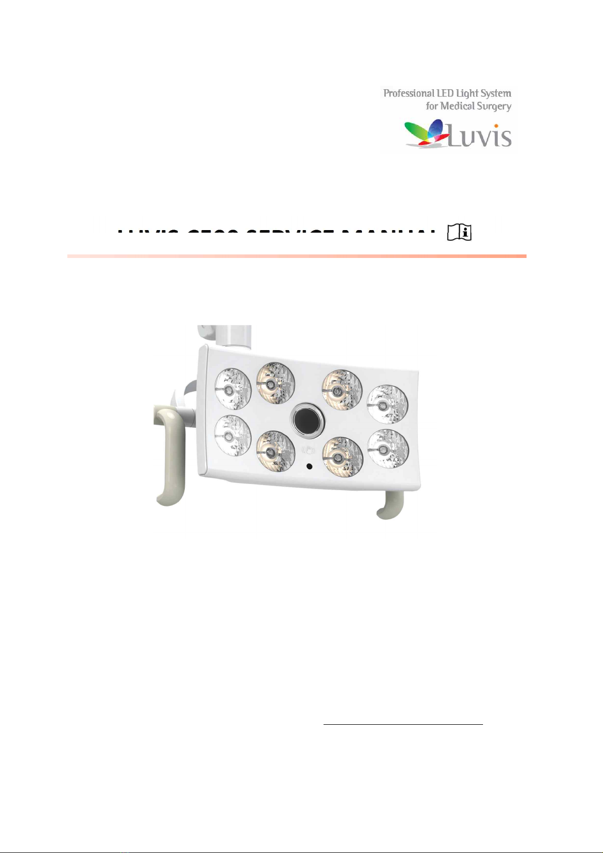
LUVIS C500 SERVICE MANUAL
(V2.1) 10/11/2017
Dantal Light
DENTIS CO., LTD.
99, Seongseoseo-ro, Dalseo-gu, Daegu, Korea
Tel. 82-53-583-2804 FAX. 82-53-583-2806 www.dentis.co.kr / www.luvis.co.kr

Professional LED Light System for All of Surgery Application
2
CONTENTS
1. Standard ..................................................................................................................................................................................... 4
2. Warning ...................................................................................................................................................................................... 5
3. Symbol......................................................................................................................................................................................... 7
4. Safety instruction.................................................................................................................................................................... 8
5. LIGHTHEAD specification .................................................................................................................................................... 9
5.1 Technical specification (In accordance with EN/ISO 9680: 2014) .......................................................................... 9
5.2 Electrical specification (In accordance with IEC 60601-1) .................................................................................... 10
5.3 Mechanical specification .............................................................................................................................................. 10
5.4 Camera(optional) specification ................................................................................................................................... 11
6. Other characteristic ............................................................................................................................................................ 11
7. Tool for installation............................................................................................................................................................. 11
8. Product Installation ............................................................................................................................................................ 12
8.1 Components name ......................................................................................................................................................... 12
8.2 CHAIR TYPE Installation ................................................................................................................................................. 16
8.3 MOBILE TYPE Installation .............................................................................................................................................. 18
8.4 WALL TYPE Installation .................................................................................................................................................. 24
8.5 CEILING TYPE Installation .............................................................................................................................................. 26
9. Electrical connection .......................................................................................................................................................... 30
9.1 Wiring Diagram ............................................................................................................................................................... 31
10. USE .......................................................................................................................................................................................... 33
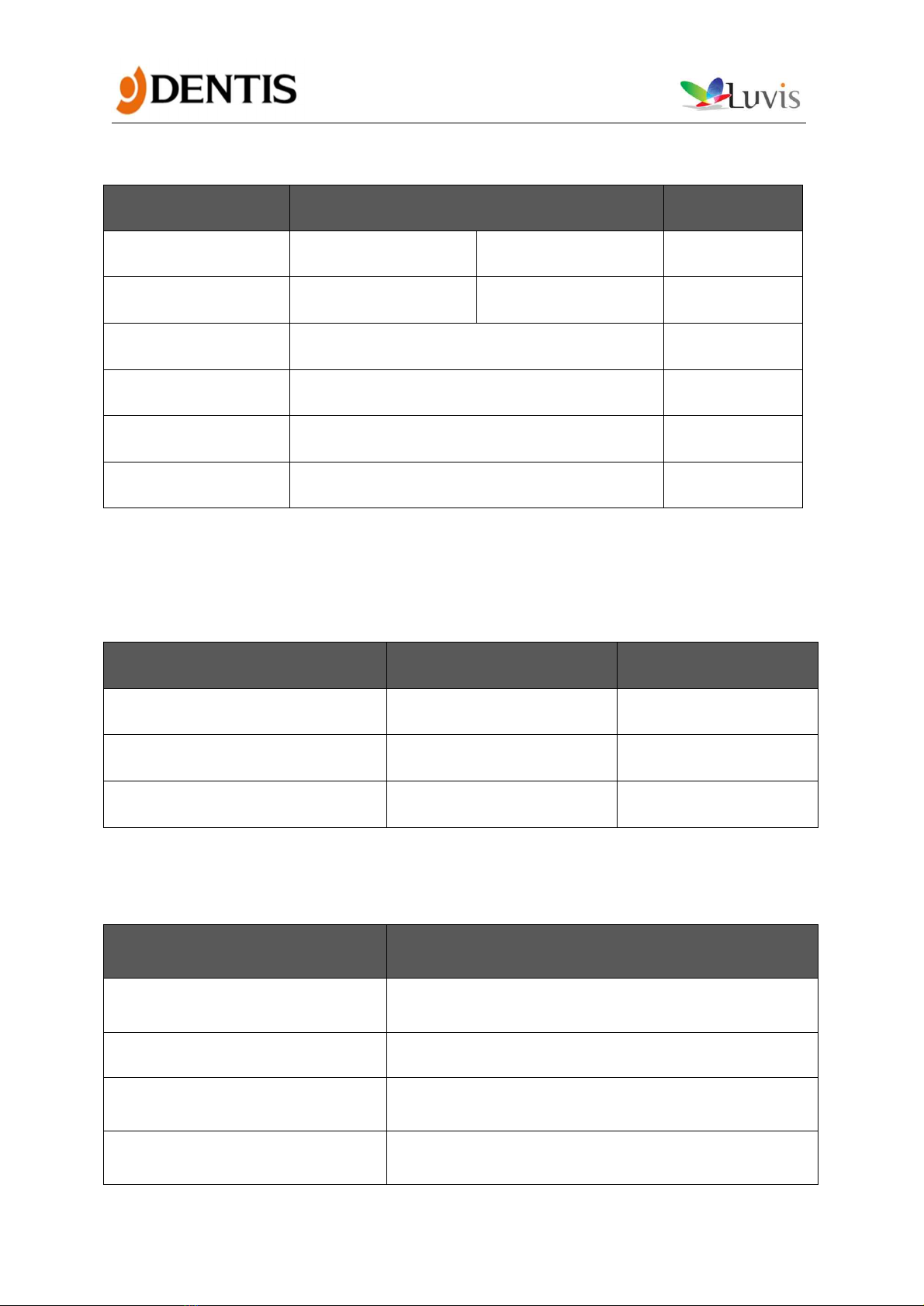
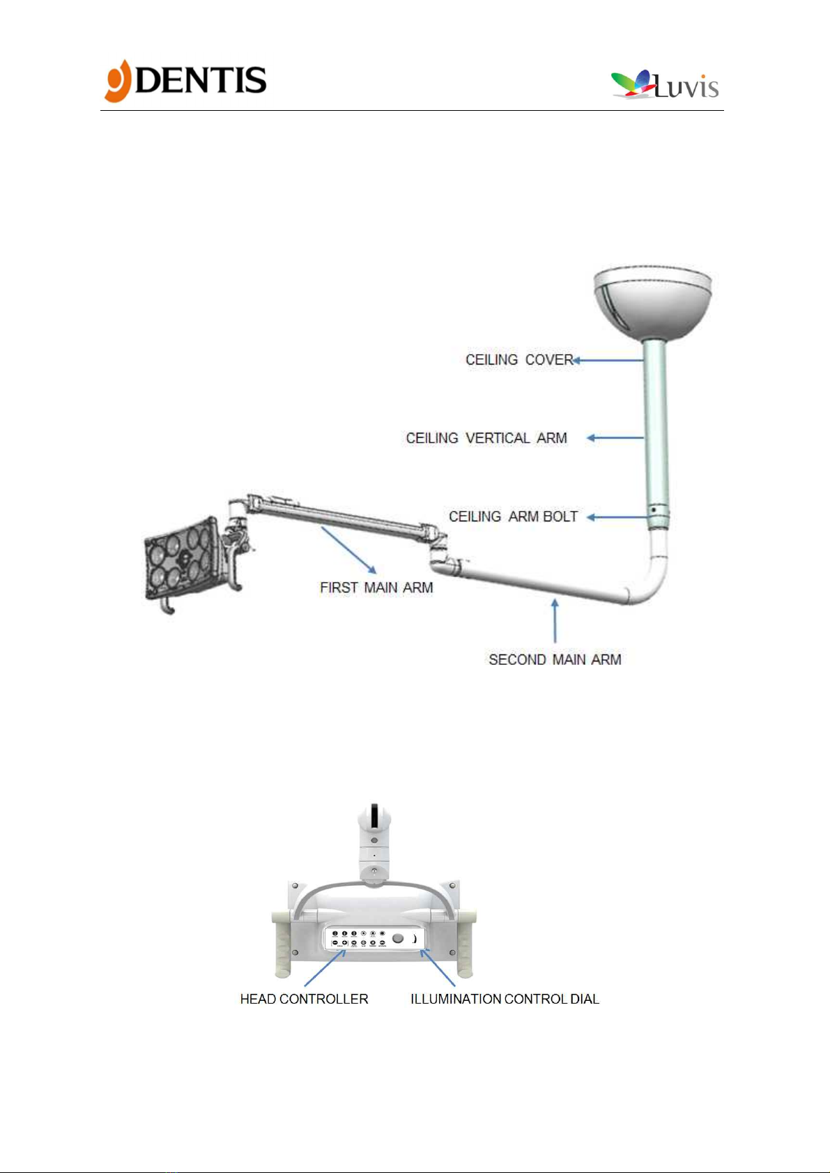
10.1 HEAD CONTROLLER ...................................................................................................................................................... 33

Professional LED Light System for All of Surgery Application
3
10.2 Remote Control (Optional) ......................................................................................................................................... 34
10.3 RESIN COVER (Optional) ............................................................................................................................................. 35
10.4 HANDLE ........................................................................................................................................................................... 35
10.5 SENSOR ........................................................................................................................................................................... 36
10.6 Positioning...................................................................................................................................................................... 37
11. Setting .................................................................................................................................................................................... 38
11.1 Adjusting the balancing of the ARM ........................................................................................................................ 38
11.2 OperOperating range of HEAD ARM ........................................................................................................................ 39
11.3 Operating range of MAIN ARM ................................................................................................................................. 40
11.4 Adjust tension ............................................................................................................................................................... 44
12. Model designation ........................................................................................................................................................... 46
13. List of component ............................................................................................................................................................ 48
“WARNING: Modification of this equipment is not allowed”

Professional LED Light System for All of Surgery Application
4
1. Standard
Ÿ Certification of DENTIS
ž ISO 9001:2008
ž EN ISO 13485:2012
Ÿ Relevant EC Directives: 93/42/EEC Medical Device Directive as amended by
2007/47/EC, Annex I and Annex VII.
Ÿ Applied Standards:
ž EN ISO 15223-1:2012, Medical devices – Symbols to be used with medical
device labels, labelling and information to be supplied
ž EN 1041:2008, Information supplied by the manufacturer with medical devices
ž EN ISO 13485:2012, Medical devices – Quality management systems –
Requirements for regulatory purpose
ž EN ISO 14971:2012, Medical devices – Application of risk management to
medical devices
ž IEC 60601-1:2005+A1:2012, Medical electrical equipment – Part 1: General
requirements for safety
ž EN 60601-1-2:2007, Medical electrical equipment – Part 1-2: General
requirements for safety - Collateral standard: Electromagnetic compatibility –
Requirements and tests
ž EN 60601-1-6:2010, Medical electrical equipment-Part 1-6: General
requirements for safety – Collateral Standard: Usability
ž EN ISO 7010:2012, Graphical symbols – Safety colors and safety signs-Registered
safety signs
ž EN 62471:2008, Photo biological safety of lamps and lamps systems
ž EN 62366:2008, Medical devices – Application of usability engineering to
medical devices
ž EN ISO 9680:2014, Dentistry – Operating lights
ž IEC 62304:2006, Medical device software, Software life-cycle processes
Professional LED Light System for All of Surgery Application
5
2. Warning
WARNING
The instructions given in this document must be followed when handling the
product. Failure to do so may endanger the safety of the installers or users.
As well as specific information on operating the entire product and conducting
preventive maintenance, are provided in the USER’S MANUAL.
For further information, please contact our sales network or our local network.
WARNING
The electrical connections must be performed by a qualified technician only.
The electrical installation must be planned, performed and inspected by electrical
engineers.
WARNING
The LIGHTHEAD is designed to operate using AC 100-240V 50/60Hz(ADAPTER), AC
12-18V 50/60 Hz. Higher or lower voltages may affect the light intensity and
operating life of the LEDs.
Luvis(C500) is class I. equipment. In order to avoid the risk of an electric shock, the
equipment must be connected to a mains supply with PE(protective earth).
WARNING
A main control switch must be installed for turning the system power-off.
Damaged wire insulation may result in the risk of electric shock.
WARNING
The power supplies may be installed and connected only by an electrician or a
DENTIS authorized service agent.
WARNING
This product may only be repaired and special assembly work may only be carried
out by DENTIS or a company that has been authorized by DENTIS.
WARNING
Check the polarity of all electrical connections before turning on the power.
WARNING
The LIGHTHEAD brakes are adjusted during installation. Like all mechanical parts,
the brakes are subject to wear.
Check the condition of the mounting surface.
Professional LED Light System for All of Surgery Application
6
WARNING
Electromagnetic waves discharged from MRI can cause malfunction of this product.
Please keep away any device that can influence this product.
WARNING
Do not look directly into light source(LED).
WARNING
The operation and safety of the device may be affected by the removal of certain
components during servicing operations.
WARNING
All the information in this manual has been checked out carefully and discerned as
accurate one at the time of publication.
However, DENTIS takes no responsibilities of the results caused by default, omission,
or misuse of it.
WARNING
DENTIS has rights to modify the product itself or specifications of the product
without any prior notice, as well as rights not to renew that modification on this
manual.
Professional LED Light System for All of Surgery Application
7
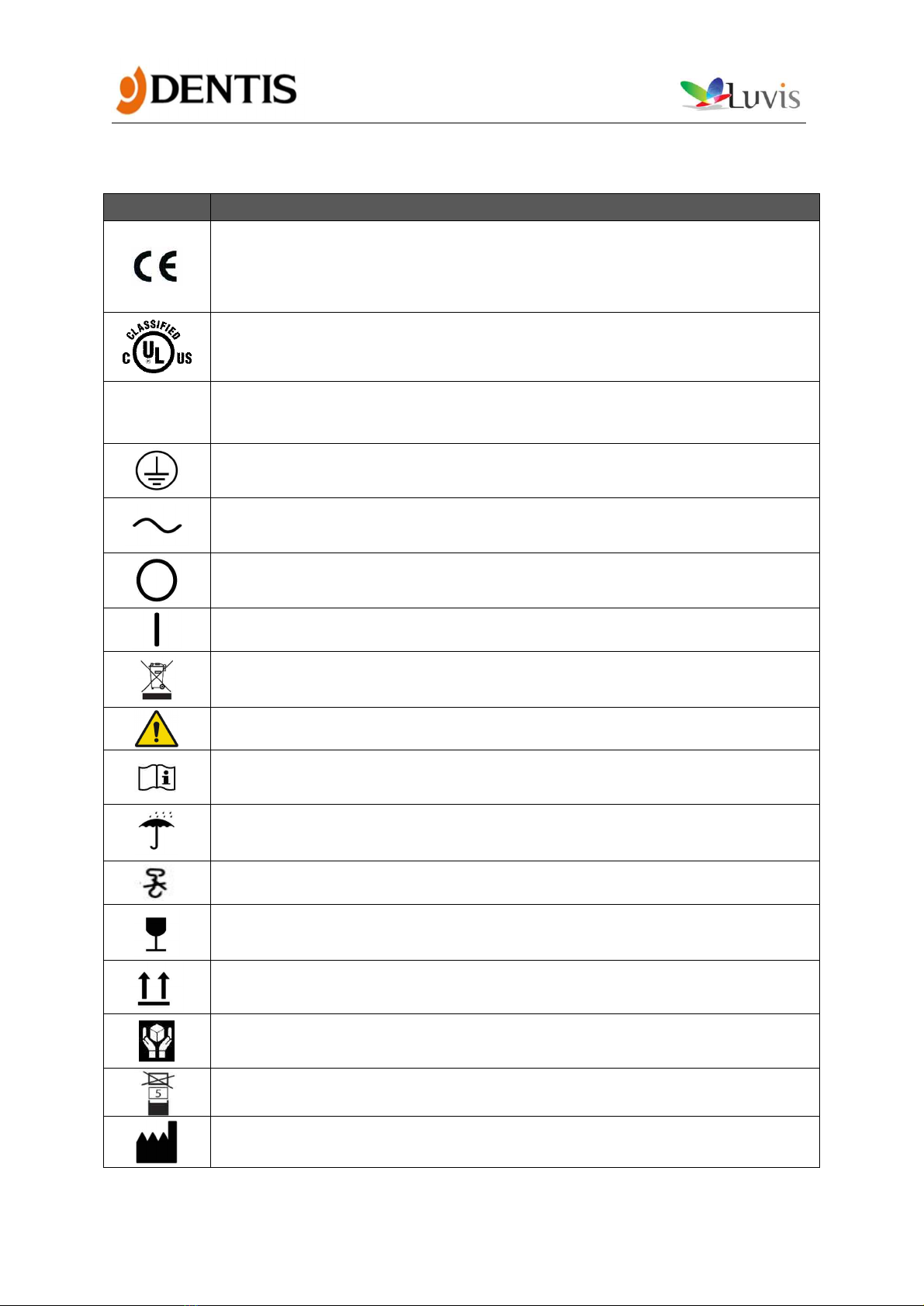
3. Symbol
Symbol
Meaning
CE label
The device bears the CE mark and complies with the requirements of
European Directive 93/42/EEC Medical Device Directive as amended by
2007/47/EC, Annex I and Annex VII.
Medical general medical equipment as to electrical shock, fire and mechanical
hazards only in accordance with ANSI/AAMI ES60601-1 & CAN/CSA-C22.2 NO.
60601-1] <E473884>
☞
Recommendation sign
Protective earth (ground)
Alternating current
Off (power: disconnect to the mains)
On (power: connection to the mains)
Do not throw away with general household waste
Warning sign
Operating instructions
Keep dry symbol
DO NOT Hand Hooks symbol
Fragile symbol
This side up
Handle with care symbol
Do not build up more than 5 boxes
Manufacture

Professional LED Light System for All of Surgery Application
8
Europe Representative
Manufacture Date
Temperature between 0˚C ~ 40˚C
Humidity between 0%RH ~ 80%RH
No pushing
Do not use this device in a bathtub, shower or water-filled reservoir
4. Safety instruction
RECOMMENDATION
Ÿ Service personnel must be trained by DENTIS or sales network.
Ÿ This document may not be reproduced, in whole or in part, without our
permission.
Ÿ Given the confidential nature of the information in this document, it is
distributed exclusively to customers and installers of DENTIS products.
Ÿ Check with the DENTIS network to ensure that you have the latest versions
of these documents.
Ÿ If you are authorized to engage the services of a contractor for all or part of
the installation and/or to manufacture certain installation subassemblies,
ensure that such subcontracting complies with the terms of the contract
which binds you and DENTIS.
Ÿ Make sure that your subcontractor is properly qualified for the job and ask
for proof of certification. Perform regular inspections at the subcontractor's
premises and make sure that the subcontractor's facilities meet your own
requirements.
Ÿ If installing on existing studs, guarantees that the studs will withstand the
new stresses must be obtained.
Ÿ Control units must meet applicable standards and fully ensure safe
operation, particularly with regard to electric shock. These guarantees must
be obtained from the subcontractors.
Ÿ DENTIS may not be held liable for any damage or injury resulting from
failure to follow these recommendations.
Professional LED Light System for All of Surgery Application
9
5. LIGHTHEAD specification
5.1 Technical specification (In accordance with EN/ISO 9680: 2014)
Ÿ STANDARD SPECIFICATION
Specifications
Unit
LUVIS 500
Remark
BASIC
RESIN COVER
Central
illuminance
Ec (@70cm)
Max
Lux
3,000
2,000
@ 4,500K
Min
Lux
50,000
30,000
Irradiance
(Ee)
W/㎡
171.86
92.27
Illuminance in
patient’s eyes
Lux
≤ 1,200
Hard shadow
mm
7 X 3
Focal Distance
Cm
70
Focal Patter (@ d10)
Cm
16.0 X 9.0
Oval shape
Focal Pattern (@ d50)
Cm
11.0 x 6.0
Oval shape
Uniformity (d50/d10)
N/A
< 70%
Color temperature
(3steps)
K
4,000/4,500/5,000
2,000 - 2,500
Selectable
C.R.I(Ra)
N/A
95
@ 4,000K
* Optical values are measured with a tolerance of ±10%

Professional LED Light System for All of Surgery Application
10
5.2 Electrical specification (In accordance with IEC 60601-1)
Ÿ TECHNICAL DATA
Content
LUVIS C500
Remark
Input
AC 12 - 18 V, 50/60 Hz,
24 VA
Chair Type
AC 100 - 240 V, 50 - 60 Hz,
38 - 52 VA
Without Camera Type
AC 100 - 240 V, 50 - 60 Hz,
50 - 70 VA
With Camera Type
Output (Adapter)
DC 15V, 1.2 A
Nomal
DC 15V, 1.7A
Camera
LED lamp life
50,000h
WARNING
Please use be connected to a chair that can limit the power supply.
If the power supply is not a dental chair, use the special adapter, which Must
provided by the DENTIS.
5.3 Mechanical specification
Specifications
Length(mm)
Weight(kg)
Remark
LED HEAD
284 x 165 x 118
1.6
Head
1.75
With RESIN COVER
4.9
With INTERNAL
CAMERA
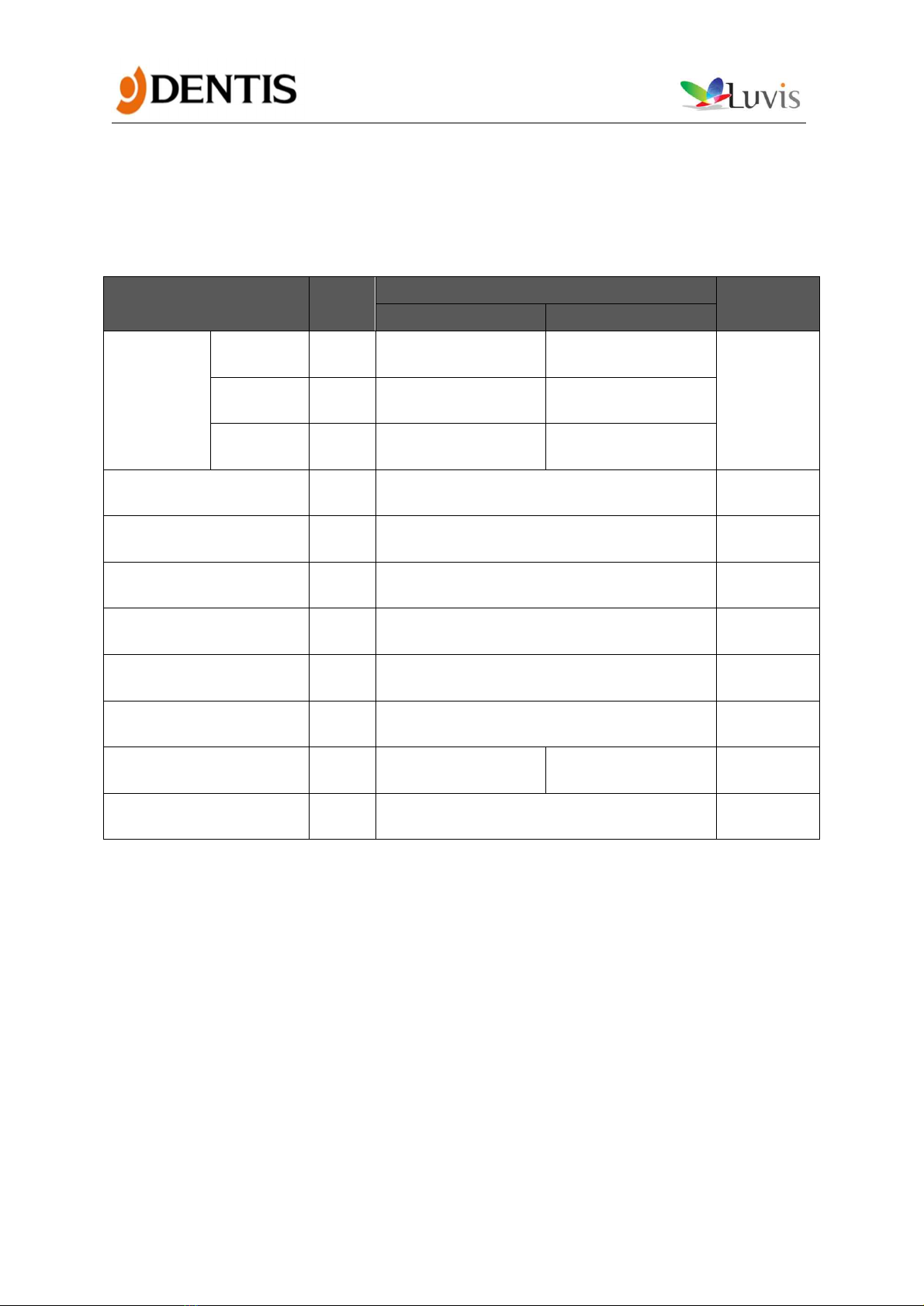
MAIN ARM
-
4.4
FIRST MAIN ARM+
SECOND MAIN ARM
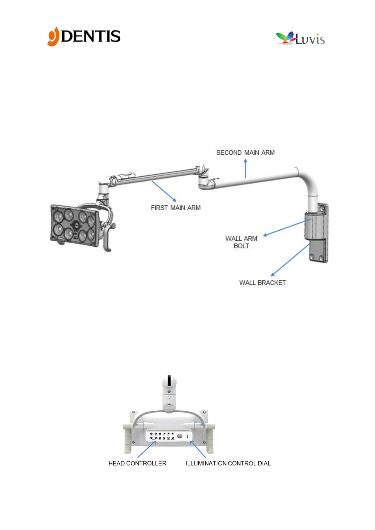
WALL BRACKET
2.3
CEILING VERTICAL
ARM
2.0
CEILING MOUNTING
SET
4.0
MOBILE VERTICAL
ARM
6.5
Professional LED Light System for All of Surgery Application
11
5.4 Camera(optional) specification
Content
Specifications
REMARK
Zoom Ratio
10X Optical Type
30X Optical Type
SONY BLOCK
CAMERA
Min. Object Distance
10mm to 800mm
600mm to 800mm
(Tele end)
Image Point
Approx. 2.38 Megapixels
Image Sensor
1/2.8 type Exmor CMOS
Video System
Full HD 1080p, 1080i, 720p, 720i
Video Output Signal
3G HD-SDI SMPTE 424M, HD-SDI 292M
75Ω BNC
* Select one of the two types of cameras to install
6. Other characteristic
Specifications
LUVIS C500
Remark
Protection against electric shock
Class I Protection
Protection against harmful ingress
of water or particulate matter
Ordinary
Method of sterilization
See the USER’S MANUAL
7. Tool for installation
Tool
Description
Allen wrench (1.5mm, 2mm, 3mm)
To adjust the head arm tension
To adjust the 1st MAIN ARM tension
“+” Driver
To install the screw
“-” Driver
To install the screw
To remove the arm cover
Long-nose
To adjust the head arm tension
To adjust the 1st MAIN ARM tension

Professional LED Light System for All of Surgery Application
12
8. Product Installation
8.1 Components name
CHAIR TYPE

Professional LED Light System for All of Surgery Application
13
MOBILE TYPE
Professional LED Light System for All of Surgery Application
14
WALL TYPE
Professional LED Light System for All of Surgery Application
15
CEILING TYPE
Professional LED Light System for All of Surgery Application
16
8.2 CHAIR TYPE Installation
No.
Installation Guide
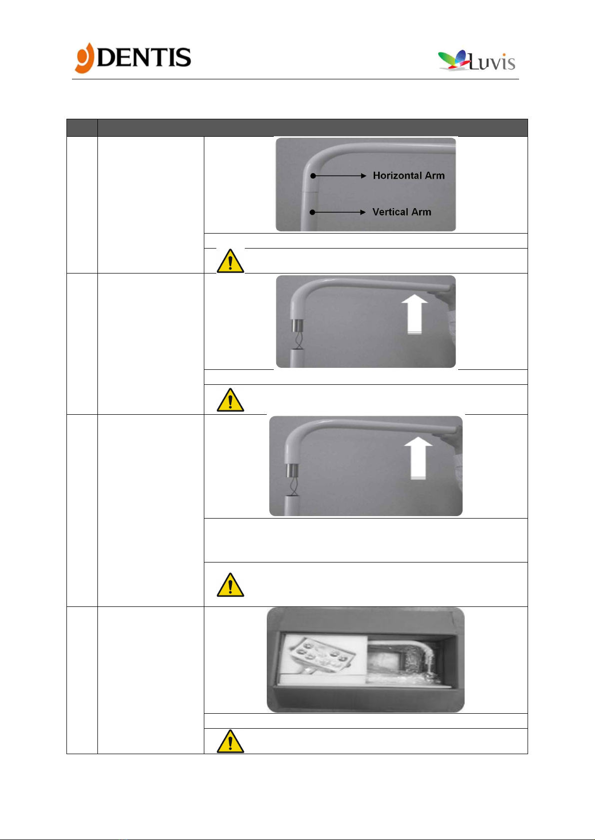
1
Initial condition
· Initial condition of existing halogen
- Check the power off
2
Arm detachment
· Lift the horizontal Arm up.
- Please turn off the chair power
- Be careful with the polarity(DC Input only)
3
Segregation wires
· Cut the Wires, leaving 10cm margins from the top of the
Vertical Arm
· Remove wire covers, leaving about 1 cm exposed
- Check the arm bolt size before installation.
- Avoid pressure of wire
- Avoid peeling of the paint on the arm
4
Check
packaging
· Check the product releasing condition
- If damage is found, contact DENTIS
Professional LED Light System for All of Surgery Application
17
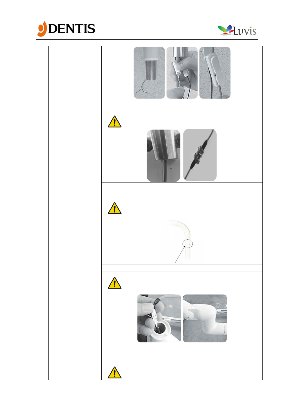
5
Wiring &
connecting
· wiring & connecting chair arm and SECOND MAIN ARM.
· INTERNAL CAMERA Model is connected to ADAPTER
- Please turn off the chair power
- Be careful with the polarity(DC Input only)
6
COAXAL CABLE
Connecting
(INTERNAL
CAMERA Model
ONLY
· SECOND MAIN ARM connected to the chair
· Connect the cable to the video transmission device
- Check the arm bolt size before installation.
- Avoid pressure of wire
- Avoid peeling of the paint on the arm
7
SECOND MAIN
ARM connecting
· SECOND MAIN ARM connected to the chair
- Check the arm bolt size before installation.
- Avoid pressure of wire
- Avoid peeling of the paint on the arm
8
FIRST MAIN ARM
connecting
· Connecting SECOND MAIN ARM and FIRST MAIN ARM chair
arm (including head)
· Check the wire(wire harnesses) condition and connecting
- Avoid pressure of wire
- Avoid peeling of the paint on the arm
Professional LED Light System for All of Surgery Application
18
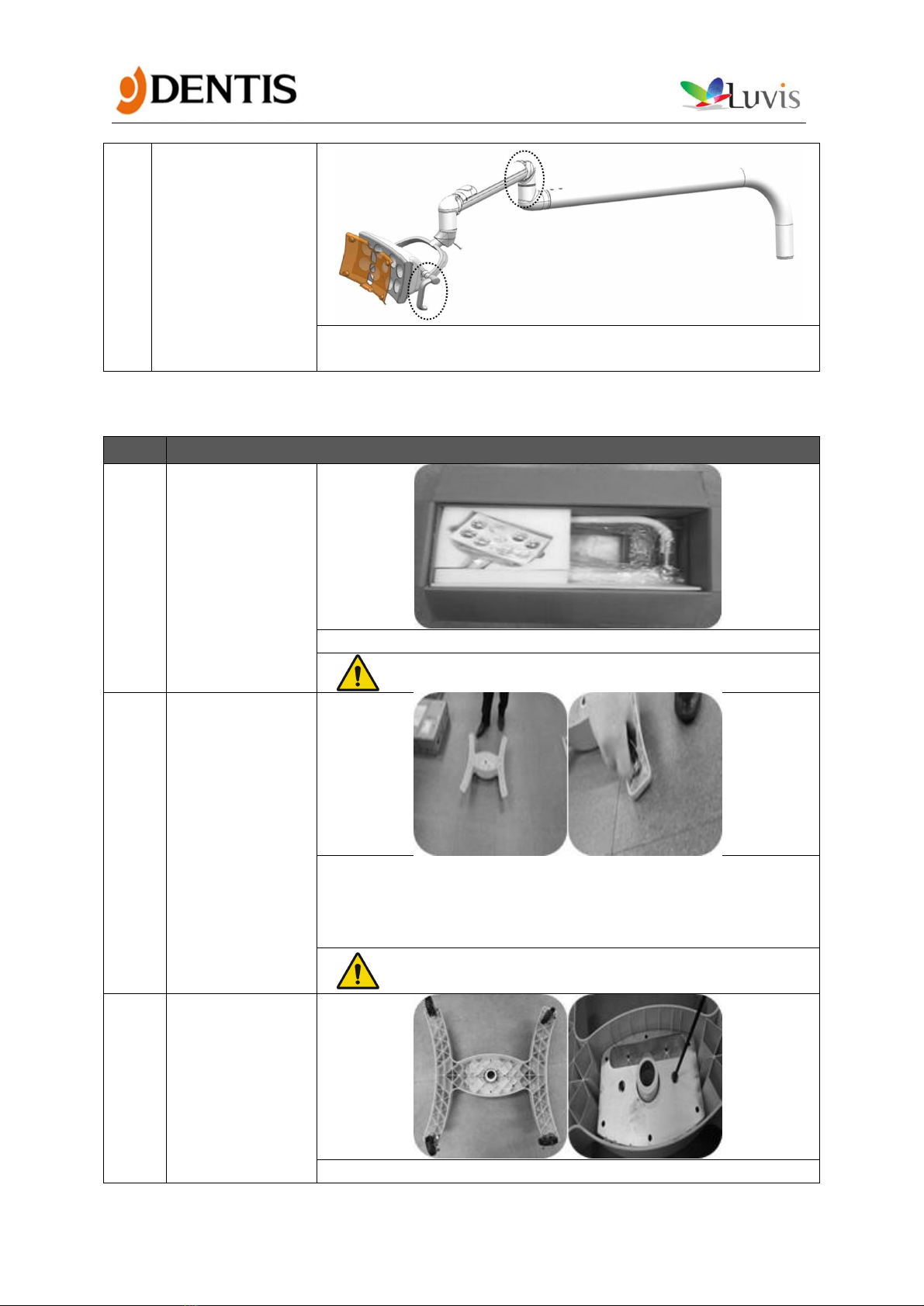
9
Completion
· Handle R/L(Check direction of) combinations
· Check the operation
8.3 MOBILE TYPE Installation
No.
Installation Guide
1
Check
packaging
· Check the product releasing condition
- If damage is found, contact DENTIS.
2
CASTER
Combination
· Open the BASE BODY BOX, take out the product
· Put face down on the floor, after checking the conditions
· Insert the CASTERs to the BASE BODY by pressing them with
your hand(4EA))
- We recommend that you put gloves on, while
working on this step.
3
BASE WEIGHT
Combination
· Properly align the center hole of WEIGHT to the pole inside the
Professional LED Light System for All of Surgery Application
19
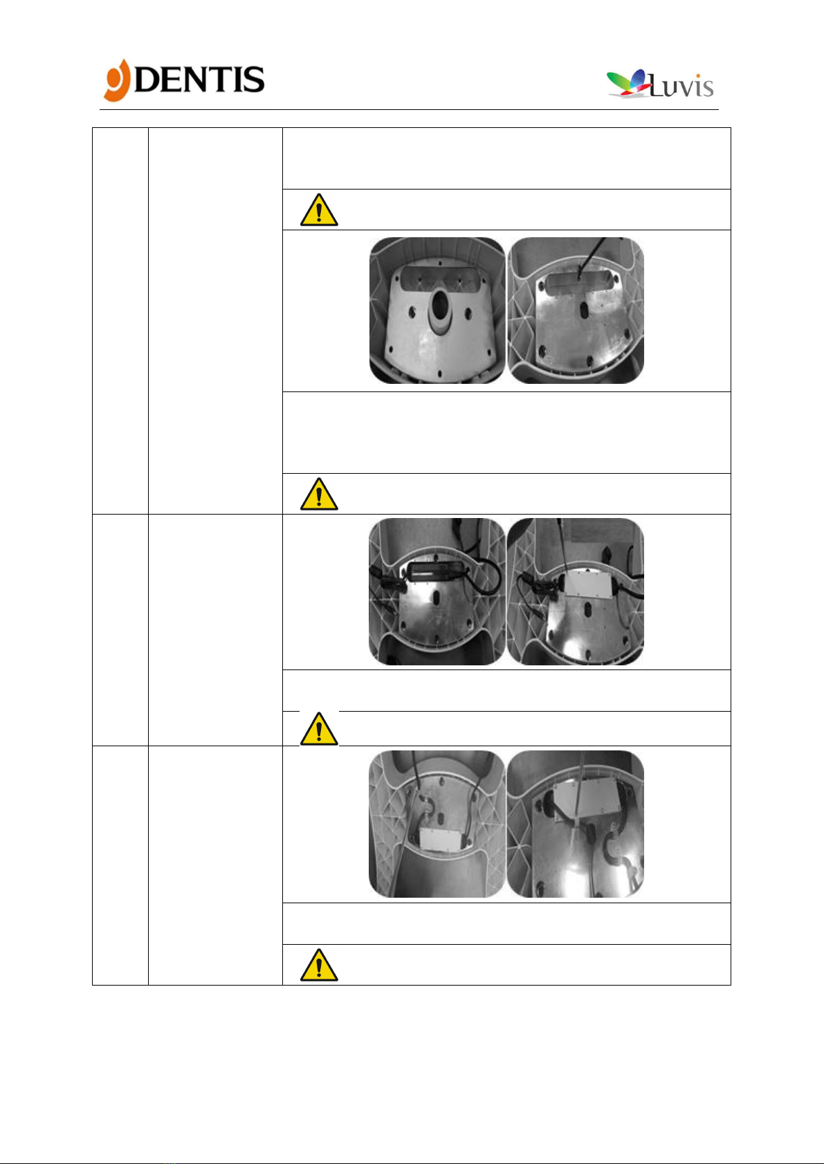
BASE BODY and insert the BASE WEIGHT to the BASE BODY.
· Insert the M6 X L35 Hexagon screws and tighten them with a
5mm Allen wrench
- Be careful finger injury. When insert a BASE
WEIGHT.
· Properly align the center hole of WEIGHT to the pole inside the
BASE BODY and insert the BASE WEIGHT to the BASE BODY.
· Insert the M6 X L55 Hexagon screws and tighten them with a
5mm Allen wrench
- Be careful finger injury When insert a BASE WEIGHT.
- Check the BASE WEIGHT’s orientation.
4
ADAPTER
Combination
· Insert the adapter into the hole in the BASE WEIGHT
· Cover with bracket and tighten them with M3 X L6 bolts
- You must Avoid pressure of wire.
5
Cable fixing
· Secure the AC cables with cable holder M4 X L6 and bolts
· Secure the AC cables with cable holder M3 X L6 and bolts
- It must be secured by bending as shown in the
figure.
Professional LED Light System for All of Surgery Application
20
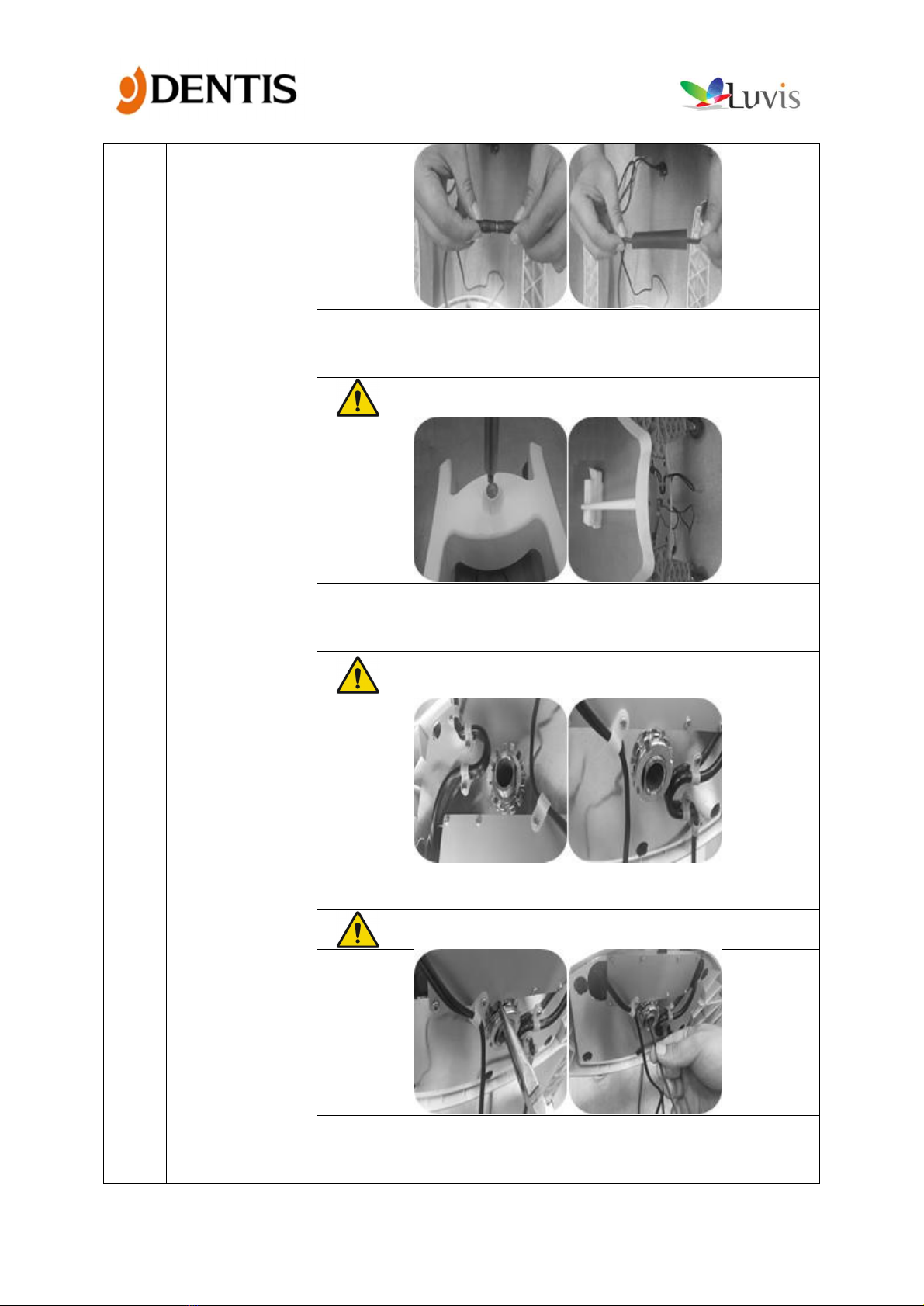
6
Harness
Connection
· ADAPTER DC Cable and MOBILE VERTICAL ARM HARNESS
connection
· Fixed using a shrink tubing
- The cable must not be fallen.
7
VERTICAL ARM
Combination
· Combining MOBILE VERTICAL ARM after reverse the BASE
BODY
· 90 ° degree Tilt
- Be careful with peeling of the paint on the arm
- Please be sure you lock the caster after work
· Insert the LOCK WASHER
· Secure the LOCK NUT by using the long-nose
- The locknut must be secured.
· Bend the lock nut by using the long-nose
· Insert the step 6 harness through the hole in the MOBILE
VERTICAL ARM
Table of contents
Other DENTIS Dental Equipment manuals


