Denwa Communications DW-GTW-AC-E1030 User manual


1Introduction
This document provides a hardware description of the DW-GTW-AC-E1030
(hereafter referred to as device) and step-by-step procedures for mounting
and cabling the device.
The device supports the following interfaces:
●Four Gigabit Ethernet (10/100/1000Base-T) LAN ports
●Single E1/T1 port interface over a single copper wire pair (PRI interface
is a customer-ordered item
●Two USB ports for optional, USB storage services
●Serial console port (RJ-45) for device management
2Package content
Follow the procedure below for unpacking the carton in which the device is
shipped.
●DW-GTW-AC-E1030
●Four anti-slide bumpers for desktop installation
●Two mounting brackets for 19-inch rack mounting
●One AC power cable

3Physical Description
This section provides a physical description of the device.
3.1 Physical Dimensions
The device's physical dimensions and weight are listed in the table below:
Table 3-1: Physical Dimensions
Physical Specification
Value
Dimensions (H x W x D)
4.37 (1U) x 31.0 cm x 21.0 cm (1.72 x 12.2 x 8.3
in.)
Weight
2.0 kg (4.4 lbs.)
Environmental
Operational: 0 to 40°C (32 to 104°F)
Storage: -25 to 70°C (-13 to 158°F)
Humidity: 10 to 90% non-condensing
MTBF
373,972
3.2 Front Panel Description
This section describes the device's front panel.
3.2.1 Ports and Buttons
The device's front panel is shown in the figure below and described in the
subsequent table.
Figure 3-1: Front Panel

Table 3-2: Front Panel Description
Item
#
Label
Description
1
POWER / STATUS
LEDs indicating the status of the power and
reboot/initialization.
2
//
Reset pinhole button for resetting the device and
optionally, for restoring the device to factory
defaults. To restore the device to factory defaults,
do the following:
With a paper clip or any other similar pointed
object, press and hold down the pinhole button for
at least 12 seconds, but no longer than 25
seconds
3
CONSOLE
RJ-45 port for RS-232 serial communication
4
LAN
Up to four Gigabit Ethernet (10/100/1000Base-T)
ports for connecting to LAN network (IP phones,
computers, or switches). These ports support half-
and full-duplex modes, auto-negotiation, and
straight or crossover cable detection.
5
PRI
Single E1/T1 port interface (RJ-48).
Note: PRI interface is a customer-ordered item.
6
USB
Two USB 2.0 ports, which can be used, for
example, for various storage capabilities using an
external USB hard drive or flash disk (disk on key).
3.2.2 LED Descriptions
This section describes the LEDs provided on the front panel.
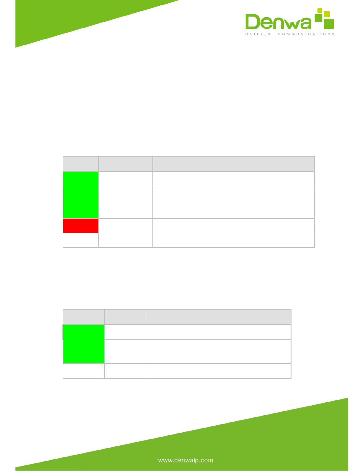
3.2.3.1 Operational Status LED
The STATUS LED indicates the operating status, as described in the table
below.
Table 3-3: STATUS LED Description
LED Color
LED State
Description
Green
On
Device is operational.
Fast Flashing
Initial rebooting stage.
Software upgrade (.cmp file) in process (currently
supported only by Software Version 6.8).
Red
On
Boot failure.
-
Off
Advanced rebooting stage.
3.2.3.2 LAN Interface LED
Each Ethernet port provides a LED for indicating LAN operating status, as
described in the table below.
Table 3-4: LAN LED Description
LED Color
LED State
Description
Green
On
Ethernet link established.
Flashing
Data is being received or
transmitted.
-
Off
No Ethernet link.
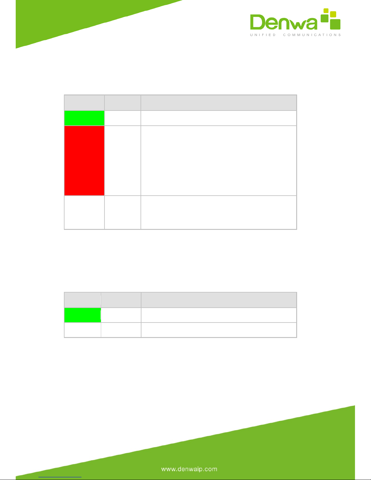
3.2.3.3 E1/T1 LEDs
The E1/T1 trunk port provides a LED for indicating operating status, as
described in the table below:
Table 3-5: E1/T1 LED Description
Color
State
Description
Green
On
Trunk is synchronized (normal operation).
Red
On
Loss due to any of the following signals:
●LOS - Loss of Signal
●LOF - Loss of Frame
●AIS - Alarm Indication Signal (the Blue
Alarm)
●RAI - Remote Alarm Indication (the
Yellow Alarm)
-
Off
Failure / disruption in the AC power supply or
the power is currently not being supplied to the
device through the AC power supply entry.
3.2.3.4 Power LED
The POWER LED indicates the power supply status, as described in the table
below.
Table 3-6: POWER LED Description
LED Color
LED State
Description
Green
On
Power is received by the device.
-
Off
No power received by the device.
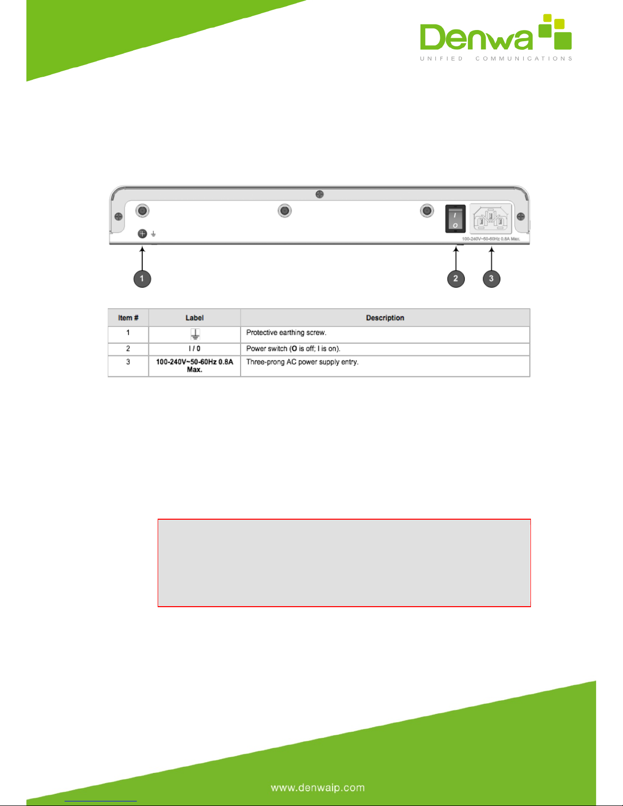
3.3 Rear Panel Description
The device's rear panel is shown in the figure below and described in the
subsequent table.
Figure 3-2: Rear Panel
Table 3-7: Real Panel Description
4Mounting the Device
The device can be mounted in one of the following ways:
Placed on a desktop
Installed in a standard 19-inch rack
Warning: Do not place any equipment directly on top of the
device or adjacent to its sides (at least 13-cm separation). In
addition, if you are mounting the device in a 19-inch rack, ensure
that at least a 3U separation is maintained between the device and
other mounted devices or equipment.
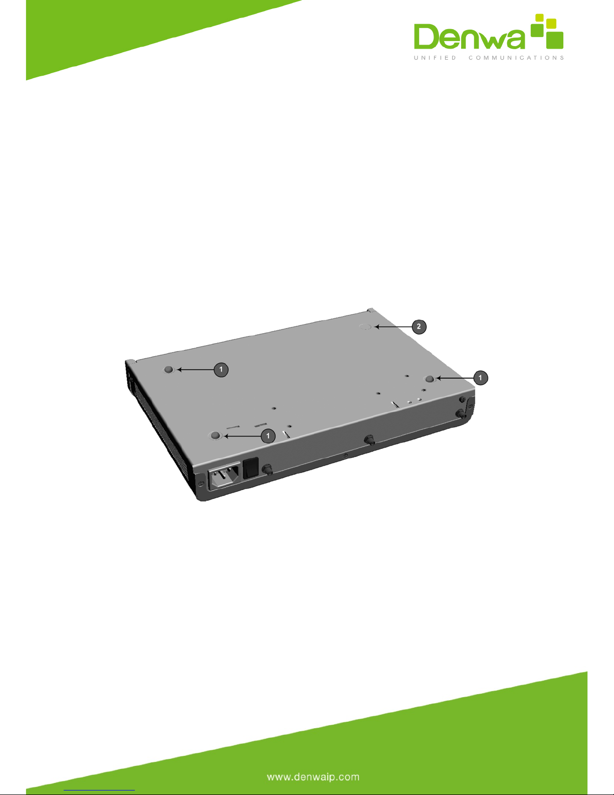
4.1 Desktop Mounting
The device can be placed on a desktop when its four anti-slide bumpers
(supplied) are attached to the underside of the device.
To attach the anti-slide rubber bumpers to the device:
1. Flip the device over so that its underside faces up.
2. Locate the four anti-slide grooves on the underside - one in each
corner.
3. Peel off the adhesive, anti-slide rubber feet and stick one in
each anti-slide groove.
Figure 4-1: Location for Applying Rubber Feet
·1 = Mounted anti-slide rubber feet
·2 = Anti-slide groove
4. Flip the device over again so that it rests on the rubber feet and
place it in the required position on a desktop.
4.2 19-Inch Rack Mounting
The device can be installed in a standard 19-inch rack by implementing one of
the following mounting methods:
●Placing it on a pre-installed shelf in a 19-inch rack

●Attaching it directly to the rack’s frame using the device's mounting
brackets (supplied) that need to be attached to the chassis – see
Section 4.2.2 on page 21
Rack Mount Safety Instructions
When installing the chassis in a rack, implement the following safety
instructions:
·Elevated Operating Ambient Temperature: If installed in a
closed or multi-unit rack assembly, the operating ambient
temperature of the rack environment may be greater than room
ambient temperature. Therefore, consideration should be given to
installing the equipment in an environment with maximum ambient
temperature (Tma) of 40°C (104°F).
·Reduced Air Flow: Installation of the equipment in a rack
should be such that the amount of air flow required for safe
operation on the equipment is not compromised.
·Mechanical Loading: Mounting of the equipment in the rack
should be such that a hazardous condition is not achieved due to
uneven mechanical loading.
·Circuit Overloading: Consideration should be given to the
connection of the equipment to the supply circuit and the effect that
overloading of the circuits might have on over-current protection and
supply wiring. Appropriate consideration of equipment nameplate
ratings should be used when addressing this concern.
·Reliable Earthing: Reliable earthing of rack-mounted
equipment should be maintained. Particular attention should be given
to supply connections other than direct connections to the branch
circuit (e.g., use of power strips).

4.2.1 Using a Pre-installed Rack Shelf
The procedure below describes how to place the device on a pre-installed
shelf in a 19-inch rack.
To mount the device on a pre-installed shelf in the rack:
1. Before installing it in the rack, ensure that you have a pre-
installed rack shelf on which the device can be placed.
2. Place the device on the pre-installed shelf in the rack.
4.2.2 Using Mounting Brackets
The procedure below describes how to mount the device in a 19-inch rack.
Rack mounting involves placing the device on a pre-installed rack shelf and
then attaching the device's mounting brackets to the device and rack frame.
The purpose of the mounting brackets is to secure the device to the rack.
Two mounting brackets are provided:
●Left mounting bracket:
Figure 4-2: Left Mounting Bracket
●Right mounting bracket with hole for looping through an optional cable
tie (not supplied) for securing cables:
Figure 4-3: Right Mounting Bracket
To mount the device in a 19-inch rack using mounting brackets:

1. Attach the two mounting brackets (supplied) to each side of the
device's chassis, using the supplied screws, as shown in the figure
below:
Figure 4-4: Attaching the Mounting Brackets
·1 = Left mounting bracket
·2 = Attached screws
·3 = Right mounting bracket
1. Place the device on a pre-installed shelf in the rack.
2. Attach the ends of the mounting brackets (that you installed in Step 1)
to the vertical track of the rack's frame, using standard 19-inch rack bolts (not
supplied).
5Cabling the Device
This section describes the cabling of the device, which includes the following:
Grounding (earthing) the device
Connecting to the LAN
Connecting to an E1/T1 trunk
Connecting to a computer for serial communication
Connecting a USB storage device
Connecting to the power supply
5.1 Grounding the Device
The device must be connected to earth (grounded) using an equipment-
earthing conductor.

Protective Earthing
The equipment is classified as Class I EN60950 and UL60950 and must
be earthed at all times.
For Finland: "Laite on liltettava suojamaadoituskoskettimilla
varustettuun pistorasiaan."
For Norway: "Apparatet rna tilkoples jordet stikkontakt."
For Sweden: "Apparaten skall anslutas till jordat uttag."

To earth the device:
1. Connect an electrically earthed strap of 16 AWG wire (minimum)
to the chassis' earthing screw (located on the rear panel), using the supplied
washer.
2. Connect the other end of the strap to a protective earthing. This
should be in accordance with the regulations enforced in the country of
installation.
Figure 5-1: Earthing the Device
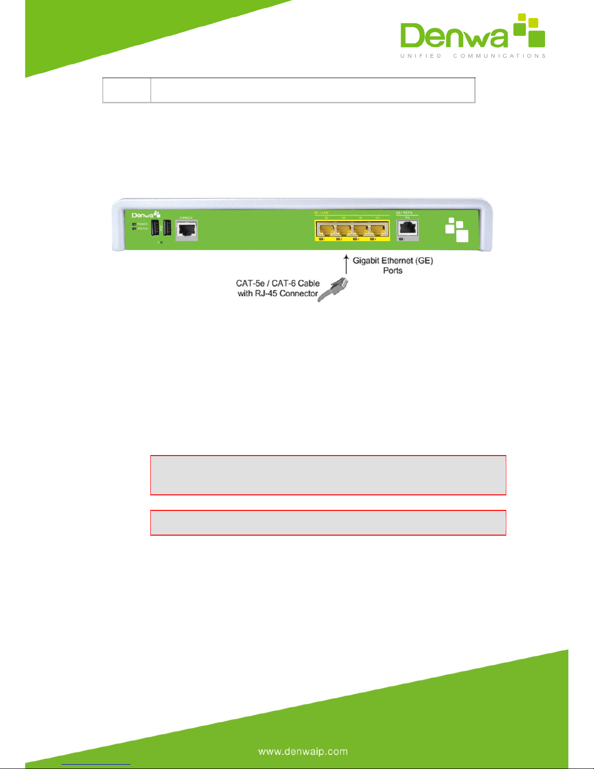
5.2 Connecting to the LAN
The device provides up to four Gigabit Ethernet (10/100/1000Base-T) ports
for connection to the LAN (e.g., computers, switches, and IP phones). These
ports support half- and full-duplex modes, auto-negotiation, and straight or
crossover cable detection.
The RJ-45 connector pinouts are described in the table below:
Table 5-1: RJ-45 Connector Pinouts for GbE
Pin
Signal Name
1
Ethernet signal pair (10/100/1000Base-T)
2
3
Ethernet signal pair (10/100/1000Base-T)
6
4
Ethernet signal pair (1000Base-T)
5
7
Ethernet signal pair (1000Base-T)
8
Shield
Chassis ground
To connect the device to the LAN:
1. Connect one end of a straight-through RJ-45 Cat 5e or Cat 6
cable to the RJ-45 port labeled S1 / LAN GE.
Figure 5-2: Cabling the LAN Ports
2. Connect the other end of the cable to the Gigabit Ethernet
network.
5.3 Connecting to an ISDN PRI (E1/T1) Trunk
The procedure below describes the cabling of the device's E1/T1 (PRI) trunk
interface.
Warning: To protect against electrical shock and fire, use a 26
AWG min wire to connect the E1 / T1 port to the PSTN.
Note: PRI interface is a customer-ordered item.

The RJ-48c trunk connector used in the cabling is wired according to the
figure below:
Figure 5-3: RJ-48c Connector Pinouts for E1/T1
ØTo connect the E1/T1 trunk interface:
1. Connect the E1/T1 trunk cable to the device’s E1/T1 port.
2. Connect the other end of the trunk cable to your PBX/PSTN switch.
Figure 5-4: Cabling E1/T1 Port
5.4 Connecting the Serial Interface to a PC
The device provides an RS-232 serial interface port on its front panel. The
serial cable adapter used for connecting the RS-232 interface is shown below:
Figure 5-5: RS-232 Cable Adapter
Table 5-2: DB-9 to RJ-45 Serial Cable Connector Pinouts
DB-9 Female
RJ-45
8
1
6
2
2
3
5
4
5
5
3
6
4
7
7
8
To connect the device's serial interface port to a PC:
1. Connect the end of the cable providing the RJ-45 connector to
the device's serial port located on the front panel, labeled CONSOLE.
Figure 5-6: Cabling Serial Port
2. Connect the other end of the cable providing the 9-pin DB
connector to the COM RS-232 communication port on your computer.
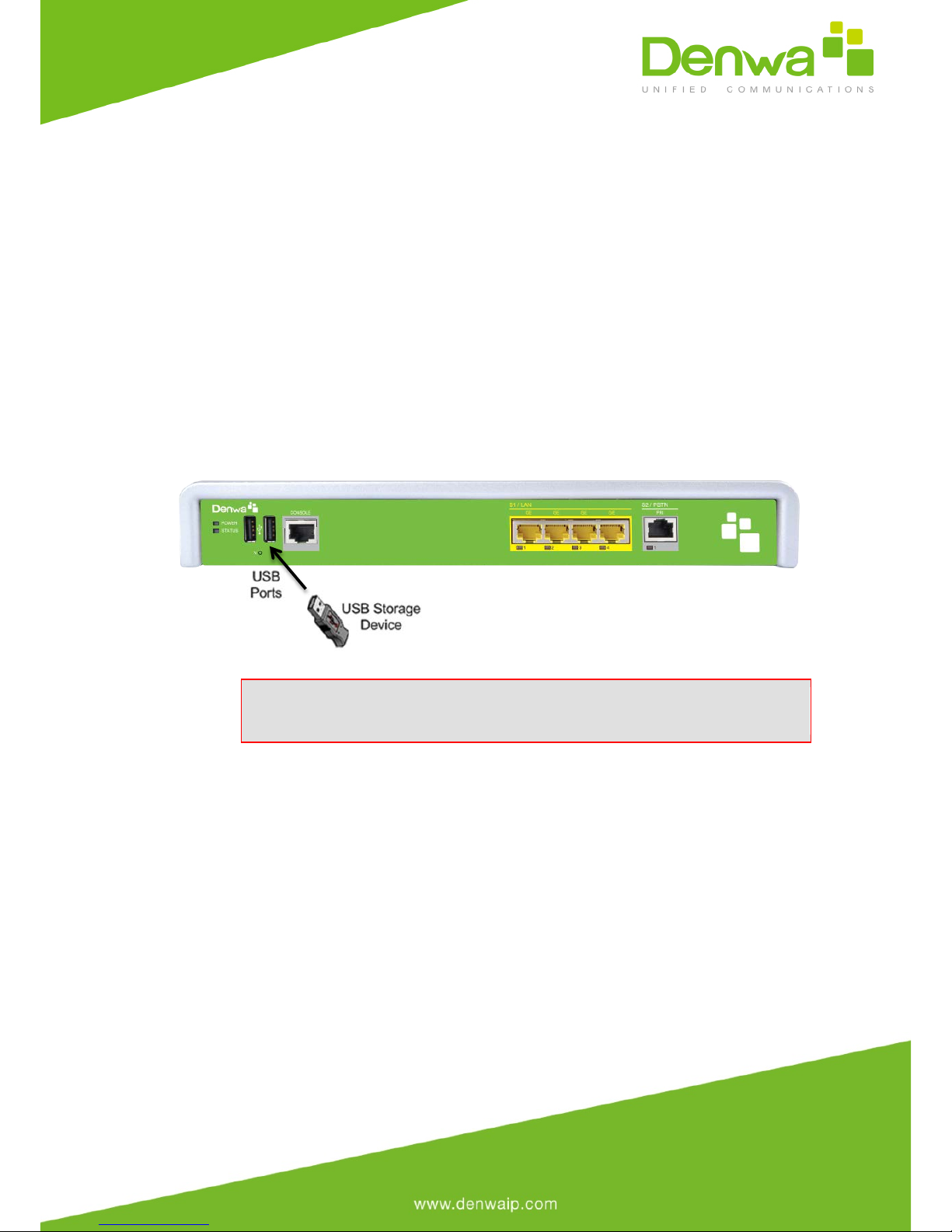
5.5 Connecting a USB Storage Device
The device supports USB storage capabilities, using an external USB hard drive
or flash disk (disk on key) connected to the device's USB port. The storage
capabilities are configured through CLI and include the following:
●Saving network captures to the USB
●Updating the device's firmware from the USB
●Updating the device's configuration from the USB
●Saving the current configuration to the USB
To connect the USB storage device:
●Connect the USB storage device to one of the USB ports located on the
front panel.
Figure 5-7: Connecting a USB Storage Device
Note: Only a single USB storage (formatted to FAT/FAT32) operation
is supported at any given time.

5.6 Connecting to the Power Supply
The device receives power from a standard alternating current (AC) electrical
outlet. The connection is made using the supplied AC power cord.
Table 5-3: Power Specifications
Physical
Specification
Value
Input Voltage
Single universal AC power supply 100 to
240V
AC Input Frequency
50 to 60 Hz
AC Input Current
0.8A
Max. Power
Consumption
20W
Warnings:
·The device must be connected to a socket-outlet providing a
protective earthing connection.
·Use only the AC power cord that is supplied with the device.

To connect the device to the power supply:
1. Connect the line socket of the AC power cord (supplied) to the
device's AC power socket (labeled 100-240V~50-60 Hz 0.8A), located on the
rear panel.
Figure 5-8: Connecting to the Power Supply
2. Connect the plug at the other end of the AC power cord to a
standard electrical outlet.
3. Press the power switch to on (I) position so that the device
receives power; the POWER LED on the front panel is lit green.
Table of contents
Other Denwa Communications Gateway manuals


