Denwa Communications DW-GTW-AC-E1060 User manual

1Introduction
This document provides a hardware description of the DW-GTW-AC-E1060 (hereafter
referred to as device) and step-by-step procedures for mounting and cabling the
device.
The device supports the following interfaces:
●2 E1/T1 port interfaces.
●4 FXS port interfaces
●4 Gigabit Ethernet ports
2Package content
Follow the procedure below for unpacking the carton in which the device is shipped.
●DW-GTW-AC-E1060
●Four anti-slide bumpers for desktop installation
●One FXS Lifeline cable adapter
●Two mounting brackets for 19-inch rack mounting
●One AC power cable
3Physical Description
This section provides a physical description of the device.
3.1 Physical Dimensions and Operating Environment
The device's physical dimensions and operating environment are listed in the table
below:
Table 3-1: Physical Dimensions and Operating Environment
Physical Specification
Description
Dimensions (H x W x D)
1U x 32 x 34.5 cm (12.6 x 13.6 inches)
Weight
2.5 kg (5.5 lbs.)
Environmental
Operational: 5 to 40°C (41 to 104°F)
Storage: -25 to 85°C (-13 to 185°F)
Humidity: 10 to 90% non-condensing
MTBF
238,834

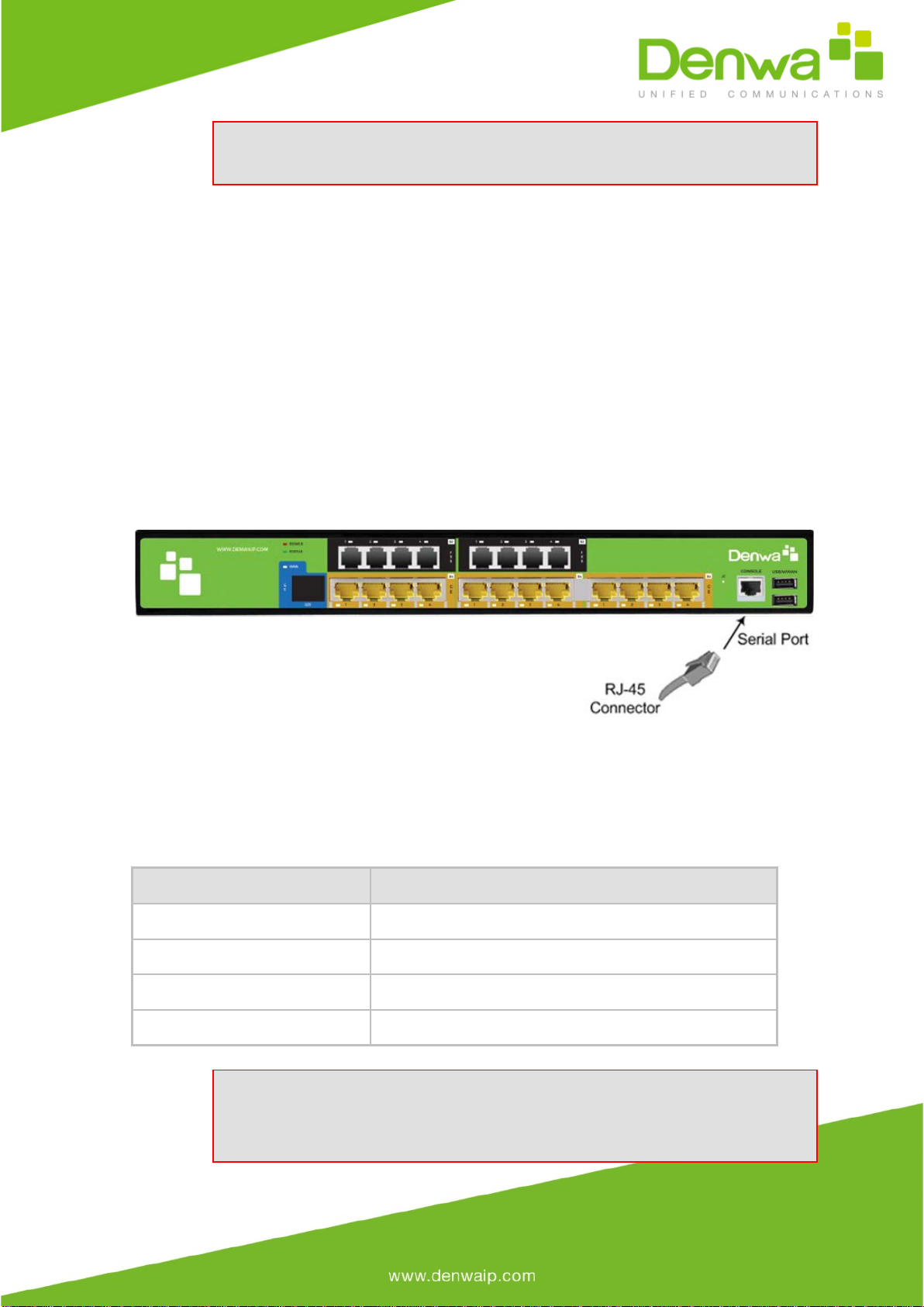
3.2 Front Panel Description
The front panel provides the telephony port interfaces, various networking ports,
reset pinhole button, and LEDs.
Table 3-2: Front Panel Description
Item
#
Label
Description
1
USB/WWAN
USB port, used for various functionalities such as saving
debug captures to a USB storage device.
2
Console
Port RJ-45 to RS-232 port for serial communication.
3
POWER /
STATUS
LEDs indicating the status of the power and
reboot/initialization.
4
PRI / Digital
Telephony port interfaces that can include two E1/T1 port
interfaces (RJ-48)
5
-
Reset pinhole button for resetting the device and optionally,
for restoring the device factory defaults. To restore the
device to factory defaults, do the following:
With a paper clip or any other similar pointed object, press and hold down
the Reset pinhole button for at least 12 seconds, but no more than 25
seconds.
6
LAN
Four 10/100/1000Base-T (Gigabit Ethernet) LAN ports for
connecting IP phones, computers, or switches. These ports
support the following features:
Half- and full-duplex modes
Auto-negotiation
Straight or crossover cable detection
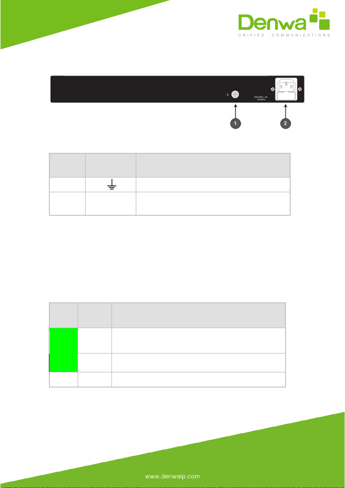
Table 3-3: Rear Panel Description
ITEM
Label
Description
1
Protective earthing screw.
2
100-240V~4A
50-60Hz
3-Prong AC power supply entry.
3.2.1 LEDs Description
The front panel provides LEDs on the device's hardware (e.g., the available telephony
interfaces). These LEDs are described in the subsequent subsections.
3.2.1.1 LAN Interface LEDs
Each LAN port provides a LED (located on its left) for indicating LAN operating status,
as described in the table below.
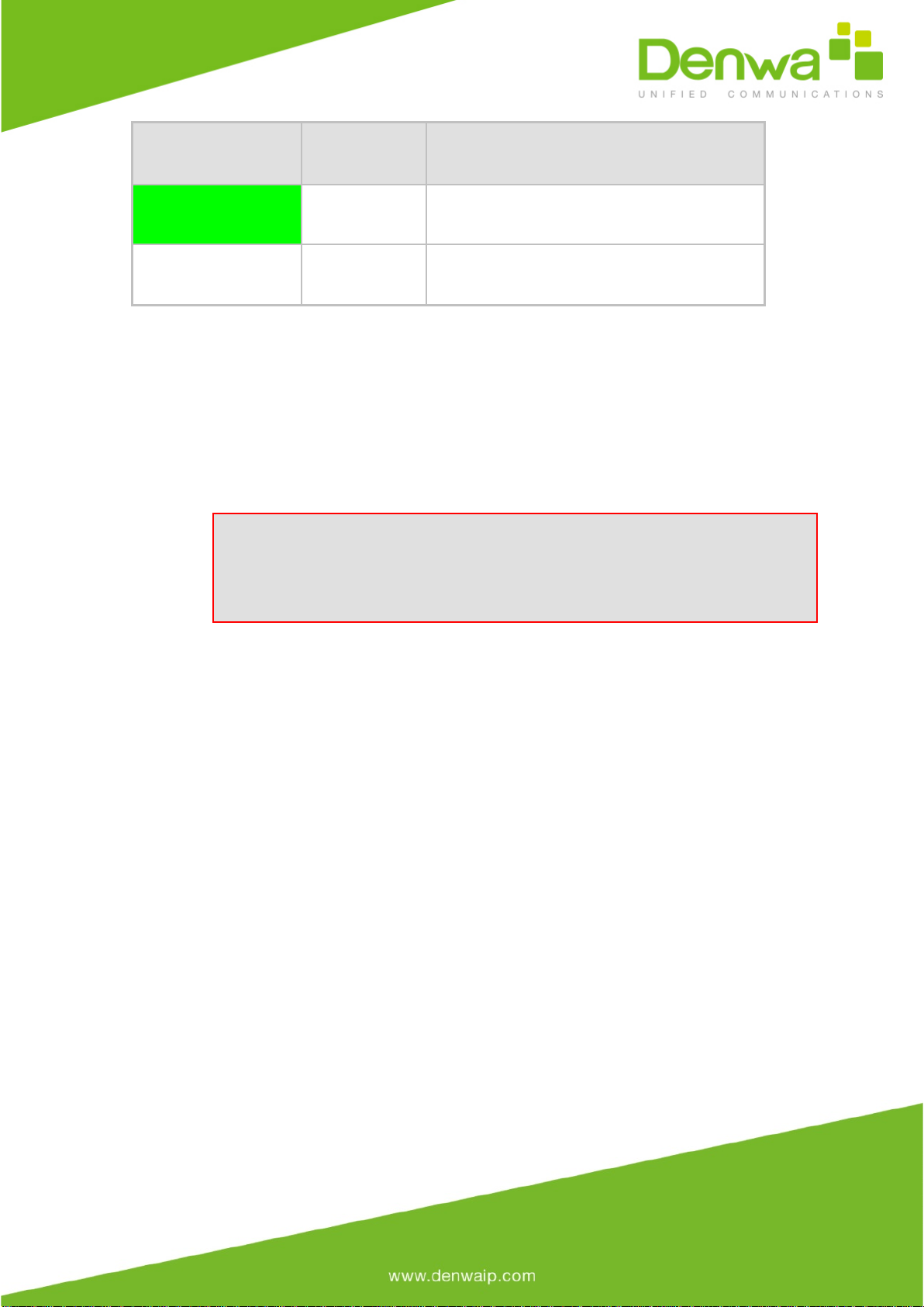
Table 3-4: LAN LEDs Description
LED
Color
LED
Staus
Description
Green
On
Ethernet link established.
Flashing
Data is being received or transmitted.
-
Off
No Ethernet link.
3.2.1.2 E1/T1 LEDs
Each trunk port provides a LED for indicating operating status, as described in the
table below:

Table 3-5: E1/T1 LEDs Description
Color State Description
Green On Trunk is synchronized (normal
operation).
Red On
Loss due to any of the following signals:
●LOS - Loss of Signal
●LOF - Loss of Frame
●AIS - Alarm Indication Signal
(the Blue Alarm)
●RAI - Remote Alarm
Indication (the Yellow Alarm)
-
Off
Failure / disruption in the AC power supply
or the power is currently not being
supplied to the device through the AC
power supply entry.
3.2.1.2 Operational Status LEDs
The STATUS LED indicates the operating status, as described in the table below.
Table 3-6: STATUS LEDs Description
LED Color LED State Description
Green
On
The device is operational and in Standalone mode
(not in High-Availability mode).
Flashing
Initial rebooting stage.
Red
On
Boot failure.
Off
Advanced rebooting stage.
1.1.1.2 Power LEDs
The POWER LED indicates the operating status, as described in the table below.
Table 3-7: POWER LEDs Description
LED Color LED State Description
Green
On
Power is received by the device.
-
Off
No power received by the device.
4Mounting the Device
The device can be mounted in one of the following ways:
●Placed on a desktop
●Installed in a standard 19-inch rack
Warning: Do not place any equipment directly on top of the device or
adjacent to its sides (at least 13-cm separation). In addition, if you are
mounting the device in a 19-inch rack, ensure that at least a 3U separation
is maintained between the device and other mounted devices or equipment.

4.1 Desktop Mounting
The device can be placed on a desktop when its four anti-slide bumpers (supplied)
are attached to the underside of the device.
To attach the anti-slide rubber bumpers to the device:
1. Flip the device over so that its underside faces up.
2. Locate the four anti-slide grooves on the underside - one in each
corner.
3. Peel off the adhesive, anti-slide rubber feet and stick one in each anti-
slide groove.
Figure 4-1: Rubber Foot Attached to Underside of Device
4. Flip the device over again so that it rests on the rubber feet and place
it in the required position on a desktop.
4.2 19-Inch Rack Mounting
The device can be installed in a standard 19-inch rack by implementing one of the
following mounting methods:
●Placing it on a pre-installed shelf in a 19-inch rack
●Attaching it directly to the rack’s frame using the device's mounting brackets
(supplied) that need to be attached to the chassis
Rack Mount Safety Instructions
When installing the chassis in a rack, implement the following safety
instructions:
·Elevated Operating Ambient Temperature: If installed in a
closed or multi-unit rack assembly, the operating ambient temperature
of the rack environment may be greater than room ambient temperature.
Therefore, consideration should be given to installing the equipment in
an environment with maximum ambient temperature (Tma) of 40°C
(104°F).
·Reduced Air Flow: Installation of the equipment in a rack should
be such that the amount of air flow required for safe operation on the
equipment is not compromised.
·Mechanical Loading: Mounting of the equipment in the rack
should be such that a hazardous condition is not achieved due to uneven
mechanical loading.
·Circuit Overloading: Consideration should be given to the
connection of the equipment to the supply circuit and the effect that
overloading of the circuits might have on over-current protection and
supply wiring. Appropriate consideration of equipment nameplate ratings
should be used when addressing this concern.
·Reliable Earthing: Reliable earthing of rack-mounted equipment
should be maintained. Particular attention should be given to supply
connections other than direct connections to the branch circuit (e.g., use
of power strips).
4.2.1 Using a Pre-installed Rack Shelf
The procedure below describes how to place the device on a pre-installed shelf in a
19-inch rack.
To mount the device on a pre-installed shelf in the rack:
1. Before installing it in the rack, ensure that you have a pre-installed rack
shelf on which the device can be placed.
2. Place the device on the pre-installed shelf in the rack.
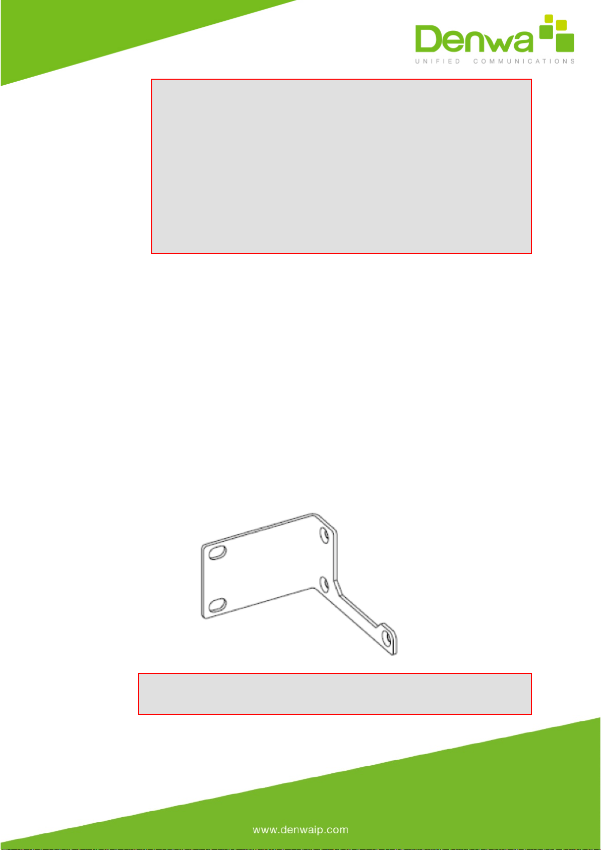
4.2.2 Using Mounting Brackets
The procedure below describes how to mount the device in a 19-inch rack. Rack
mounting involves placing the device on a pre-installed rack shelf and then attaching
the device's mounting brackets (to the device and rack frame). The purpose of the
mounting brackets is to secure the device to the rack.
Figure 4-2: Mounting Bracket (Right)
Note: 19-inch rack mounting using mounting brackets is a customer ordered
feature.

To mount the device in a 19-inch rack using mounting brackets:
1. Attach the two mounting brackets (supplied) to each side of the device's
chassis, using the supplied screws, as shown in the figure below:
Figure 4-3: Attaching the Mounting Brackets
2. Place the device on a pre-installed shelf in the rack.
3. Attach the ends of the mounting brackets (that you installed in Step 1)
to the vertical track of the rack's frame, using standard 19-inch rack bolts (not
supplied).
5Cabling the Device
This chapter describes the cabling of the device.
5.1 Grounding and Surge Protection
The device must be connected to earth (grounded) using an equipment-earthing
conductor.
Protective Earthing
The equipment is classified as Class I EN60950 and UL60950 and must be
earthed at all times.
For Finland: "Laite on liltettava suojamaadoituskoskettimilla varustettuun
pistorasiaan."
For Norway: "Apparatet rna tilkoples jordet stikkontakt."
For Sweden: "Apparaten skall anslutas till jordat uttag."
Grounding and Power Surge Protection

·
The device must be installed only in telecommunication sites /
centers in compliance with ETS 300-253 requirements "Earthing and Bonding
of Telecommunication Equipment in Telecommunication Centers".
·Prior to installation, earth loop impedance test must be performed
by a certified electrician to ensure grounding suitability at the power outlet
intended to feed the unit. It is essential that the impedance will be kept
below 0.5 ohms!
·Proper grounding is crucial to ensure the effectiveness of the
lightning protection, connect the device permanently to ground (as
described in the procedure below). The device's grounding screw must be
connected to the equipotential grounding bus bar located in the
Telecommunication rack or installation site, using a wire of 6 mm2 surface
wire. If the device is installed in a rack with other equipment, the rack
must be connected to the equipotential grounding bus bar of the
Telecommunication room, using a stranded cable with surface area of 25
mm2. The length of this cable must be as short as possible (no longer than 3
meters).
·Failing to install primary surge protectors and failing to comply with
the grounding instructions or any other installation instructions, may cause
permanent damage to the device.
·As most of the installation is the responsibility of the customer,
Denwa Corp can assume responsibility for damage only if the customer can
establish that the device does not comply with the standards specified
above (and the device is within the hardware warranty period).
·The device complies with protection levels as required by EN
55024/EN 300386. Higher levels of surges may cause damage to the device.

To ground the device:
1. Connect an electrically earthed strap of 16 AWG wire (minimum) to the
chassis' grounding screw (located on the rear panel), using the supplied washer and
fasten the wire securely using a 6-32 UNC screw.
Figure 5-1: Grounding the Device
2. Connect the other end of the strap to a protective earthing. This should be in
accordance with the regulations enforced in the country of installation.
5.2 ISDN E1/T1 Interfaces
This section describes how to cable the PRI interfaces.
5.2.1 Connecting to ISDN PRI (E1/T1) Trunks
The procedure below describes the cabling of the device's E1/T1 (PRI) trunk
interfaces.
Warning:
·To protect against electrical shock and fire, use a 26 AWG min wire
to connect T1 or E1 ports to the PSTN.
·To comply with EMC rules and regulations, use shielded twisted pair
(STP) cables for E1 interfaces on DW-GTW-AC-E1060.
Note: PRI interfaces are a customer-ordered item.

Cable specifications:
●Cable: STP cable of 26 AWG min.
●Connector Type: RJ-48c
●Connector Pinouts:
Figure 5-14: RJ-48c Connector Pinouts for E1/T1
To connect the E1/T1 trunk interface:
1. Connect the E1/T1 trunk cable to the device’s E1/T1 port.
2. Connect the other end of the trunk cable to your PBX/PSTN switch.
Figure 5-15: Cabling E1/T1 Ports
Notes:
·It does not matter which PRI port connects to which Tel entity (i.e.,
PBX or PSTN).
·To enable PSTN Fallback upon IP network connectivity issues, use
the TrunkLifeLineType parameter (PSTN Fallback upon power outage is done
by default).
5.3 Connecting to a Computer for Serial
Communication
The device provides an RS-232 serial interface port on its front panel for serial communication with a
PC.
·Port Type: RJ-45
·Cable: RJ-45 to DB-9
To connect the device's serial interface to a computer:
a. Connect the RJ-45 cable connector to the device's serial port, labeled CONSOLE.
b. Connect the other end of the cable to the COM1 or COM2 RS-232 communication port on your
PC.
Figure 5-19: Cabling Serial Interface (RJ-45)
5.4 Powering up the Device
The device receives power from a standard alternating current (AC) electrical outlet. The connection is
made using the supplied AC power cord.
Table 5-3: Power Specifications
Physical Specification
Value
Input Voltage
Single universal AC power supply 100 to 240V
AC Input Frequency
50 to 60 Hz
AC Input Current
1.5 A
Max. Power Consumption
Gateway (without OSN): 60W*
Warnings:
·The device must be connected to a socket-outlet providing a protective earthing
connection.
·Use only the AC power cord that is supplied with the device.

To connect the device to the power supply:
1. Connect the line socket of the AC power cord (supplied) to the device's AC power
socket (labeled 100-240V ~ 4A 50-60Hz), located on the rear panel.
Figure 5-21: Connecting to the Power Supply
2. Connect the plug at the other end of the AC power cord to a standard electrical
outlet.
Once you have cabled and powered-up the device, the POWER LED on the front panel lights up green.
6Maintenance – Replacing the Power
Fuse
The device contains a fuse that protects the device from excessive current. The fuse is located on the
rear panel, below the power socket. To replace the fuse, use only one of the following fuses described
in the table below:
Table 6-1: Allowed Fuses for the Device
Manufacturer
Manufacturer Part Number
BEL
5ET2.5-R
CONQUER
UDL 2.50
LITTEFUSE
021302.5MXP
Caution
For continuous protection, replace only with the same fuse type and rating fuse.
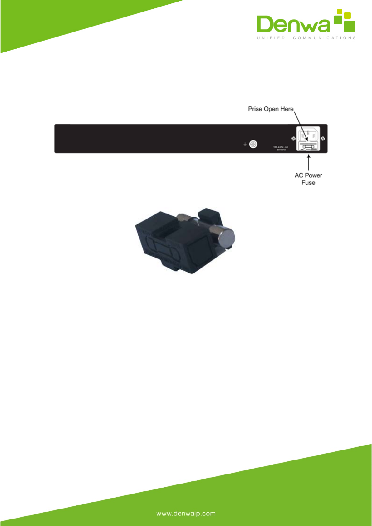
To replace the fuse:
1. Unplug the power cord from the electrical outlet.
2. Using a small flathead screwdriver, gently pries open the fuse cavity as illustrated in
the figure below:
Figure 6-1: Opening the Fuse Cavity
3. Carefully remove the fuse from the fuse cavity.
Figure 6-2: Removed Power Fuse
4. Insert the new fuse securely into the fuse cavity until you hear a click sound.
5. Reconnect the power cord and verify that the Power LED is lit green.
Table of contents
Other Denwa Communications Gateway manuals


