Denyo DLW-300LS User manual

No. D48443 02204A
Caution : Do not operate this machine before you
thoroughly read and understand this manual.
Always keep this manual near the machine.
HEAD OFFICE
2-8-5 Nihonbashi-horidomecho, Chuo-ku, Tokyo, 103-8566 Japan
TEL
+81 - 3 - 6861 – 1111
FAX
+81 - 3 - 6861 – 1181
Printed in Japan

Page No.
FOREWORD ----------------------------------------------------------------------- 1
1. SAFETY PRECAUTIONS ----------------------------------------------------------- 2
2. OUTLINE AND PART NAMES -------------------------------------------------------- 5
2-1 Outline Drawing and Name of Instrument ------------------------------------ 5
2-2 Name of Components -------------------------------------------------------- 5
2-3 Control Panel ------------------------------------------------------------- 6
3. TRANSPORTATION AND INSTALLATION ----------------------------------------------- 7
3-1 Caution in Transporting Machine ------------------------------------------ 7
3-2 Operating Angle ---------------------------------------------------------- 7
3-3 Preparations ------------------------------------------------------------- 8
3-4 Battery ------------------------------------------------------------------ 9
3-5 Battery Cable Connection ------------------------------------------------- 10
3-6 Fan Belt ----------------------------------------------------------------- 10
4. LUBRICATING OIL,COOLING WATER AND FUEL ---------------------------------------- 11
4-1 Engine Oil --------------------------------------------------------------- 11
4-2 Engine Cooling Water ----------------------------------------------------- 11
4-3 Fuel --------------------------------------------------------------------- 12
4-4 Fuel Consumption --------------------------------------------------------- 13
5. ENGINE PRESTART CHECKS -------------------------------------------------------- 15
6. STARTING AND OPERATING -------------------------------------------------------- 16
7. STOPPING THE ENGINE ----------------------------------------------------------- 18
7-1 Operating Precautions ---------------------------------------------------- 19
7-2 After Stopping ----------------------------------------------------------- 20
7-3 How to Use Automatic Air Bleeding Unit ----------------------------------- 20
7-4 Protection Device -------------------------------------------------------- 21
8. OPERATION OF THE WELDER ------------------------------------------------------- 23
8-1 Welding Cable and Polarities -------------------------------------------- 23
8-2 Selection of Welding Cable ----------------------------------------------- 24
8-3 Adjustment of Welding Current and Selection of Welding Mode -------------- 24
8-4 e mode Operation -------------------------------------------------------- 26
8-5 In Welding Operation ----------------------------------------------------- 27
8-6 Duty Cycle --------------------------------------------------------------- 27
8-7 Welding Mode Selector Switch and Arc Force Regulator --------------------- 28
8-8 VRD(Voltage Reduction Device) -------------------------------------------- 30
8-9 AC Power Supply ---------------------------------------------------------- 31
8-10 Earth Leakage Relay(Option) --------------------------------------------- 33
9. MAINTENANCE ------------------------------------------------------------------- 35
9-1 Routine Maintenance ---------------------------------------------------- 35
9-2 Engine Oil Filter -------------------------------------------------------- 37
9-3 Fuel Filter Element / Water Separator Element ---------------------------- 37
9-4 Air Cleaner Element ------------------------------------------------------ 38
9-5 Condenser ----------------------------------------------------------------- 38
10.TROUBLESHOOTING --------------------------------------------------------------- 39
11.STORAGE OF MACHINE ------------------------------------------------------------ 41
12.SPECIFICATIONS ---------------------------------------------------------------- 42
13.OUTLINE DRAWING -------------------------------------------------------------- 43
14.GENERATOR WIRING DIAGRAM ------------------------------------------------------ 44
15.ENGINE WIRING DIAGRAM --------------------------------------------------------- 46
16.ATTACHMENT -------------------------------------------------------------------- 48

- 1 -
FOREWORD
FOREWORDFOREWORD
FOREWORD
◆ This “ INSTRUCTION MANUAL ” gives a detailed description of the operation,
routine inspection, maintenance and trouble shooting of the diesel engine driven
DC Welder, and other items required for proper operation.
◆ Please read this manual carefully, especially the items with the caution marks.
◆ While the machine is placed for operation, please keep the instruction manual
near the machine.
◆ For the detailed operation and maintenance of the ENGINE, please refer to the
“Engine Operation Manual”.
Your Machine ; Model No. : DLW-300LS
Serial No. :
[ NOTE ]
[ NOTE ] [ NOTE ]
[ NOTE ] : There may be a difference between the specifications detailed in this
manual and the actual performance of the machine due to modifications
of the machine.
Symbol mark in this Manual
Symbol mark in this ManualSymbol mark in this Manual
Symbol mark in this Manual
DANGER
:
This symbol refers to a hazard or unsafe practice which can result
in severe personal injury or death.
CAUTION
:
This symbol refers to a hazard or unsafe practice which can result
in personal injury or product or property damage.
[ NOTE ]
[ NOTE ][ NOTE ]
[ NOTE ]
:
This symbol shows handling precautions for effective operation and
many years of satisfactory operation.

- 2 -
The symbols shown below are used throughout this manual to call attention to and
identify possible hazards. When you see the symbol, watch out, and follow the
related instructions to avoid the hazard. Read and follow all Safety Standards.
Only qualified persons should install, operate, maintain, and repair this machine.
During operation, keep everybody, especially children, away.
DANGER :
ELECTRIC SHOCK CAN KILL.
Do not touch output
terminals
DANGER :
DIESEL FUEL CAN CAUSE FIRE
OR EXPLOSION.
during operation. This is extremely
dangerous when your hands are wet.
Stop the machine before you touch the
terminals for connection and other
purposes.
Fuel and oil are inflammable. Never fail
to keep in flammable material away from
the machine, never smoke while refueling
and never refuel during operation.
DANGER :
ENGINE
EXHAUST GASES CAN
KILL
CAUTION :
HOT PARTS CAN CAUSE SEVERE
BURNS.
Exhaust from the engine contains
substances harmful to the human body.
Sufficient change of air is necessary
when the machine is used in places
with poor ventilation, such as in a
tunnel or indoors. Do not direct exhaust
to passers-by or houses.
Do not touch, while operating the unit,
the engine cooling fan and other places
of high temperature like the exhaust
pipe, engine and radiator.
Even when the machine is stopped, take
care that the machine has cooled down
enough before touching the engine and
the like.
DANGER : NO CONNECTION TO HOUSE
WIRING
Connecting to house wiring is very
dangerous because it may cause electric
shocks and damage the machine.
CAUTION :
Do not touch moving parts
inside the machine. Stop the
engine when you do
maintenance.
DANGER : CONFIRM CONNECTION
Damaged cables and insufficient
tightening of connection screws may
cause damage to the machine and
electric shocks. Repair damaged
cables and ensure connections are tight.

- 3 -
CAUTION :
BATTERY ECTROLYTE CAN CAUSE
EXPLOSIONS OR BURNS.
CAUTION :
In case the battery liquid
(dilute sulfur acid)
happens to come in contact
Battery contains acid and generates
explosive gases. Handle battery carefully.
Stop engine before connecting or
disconnecting battery cables, and confirm
for correct polarity for connection on
battery. Do not allow tools to cause
short circuit accident due to contacting
to terminals. Flush eyes, skin and clothes
immediately with much water if battery
acid is attached.
with clothing or skin, you must immediately
rinse it out by using a lot of water.
If the battery liquid comes into contact
with your eyes, wash it out with lot's of
water and seek medical attention immediately.
CAUTION :
HOT COOLANT CAN CAUSE
SEVERE BURNS.
CAUTION :
ARC RAYS CAN BURN EYES AND
SKIN
Do not open the radiator cap, cooling
water drain plug, or engine oil drain
plug while engine is still hot. Hot
coolant or oil can burn face, eyes, and
hand.
When welding or watching, use a hand
shield or welding helmet fitted with
proper shade of filter. Wear protective
clothing and foot protection.
CAUTION :
Read the manual and use the
machine safely and properly.
CAUTION :
Overloading shortens the life
of the machine. Use the
machine
When you rent it to others or let others
use it, explain the instruction manual
in detail and advise users to read the
manual in advance.
with appropriate AC and DC current and
appropriate duty cycle.
CAUTION :
FALLING EQUIPMENT CAN CAUSE
DEATH ACCIDENT
CAUTION :
HIGH CURRENT CAN AFFECT
PACEMAKER
Take caution in transporting the
machine. Use a lifting equipment of
enough capacity.
Pacemaker wearers should not go near
arc welding operation before consulting
their doctor

- 4 -
CAUTION :
WELDING CAN CAUSE FIRE OR
EXPLOSION.
CAUTION :
Low voltage and frequency can
damage electrical equipment
such as Motors.
①
Remove all flammables where flying
sparks can strike. If this is not
possible, tightly cover them with
approved covers.
②
Watch for fire, and keep a fire
extinguisher nearby.
Take caution or disconnect AC loads when
engine is starting or running with idle
control switch in "ON".
CAUTION :
FLYING PIECES OF METAL or DIRT
can injure eyes.
Wear safety glasses with side shields
or face shield

- 5 -
2-1 Outline Drawing and Name of Instrument
① Control panel ⑥ Air intake ⑪ Oil drain
② Fuel tank inlet ⑦ Exhaust ⑫ Radiator inlet
③ Lifting hook ⑧ Ventilation ⑬ Lock
④ Door latch ⑨ Fuel drain ⑭ Ground Terminal
⑤ Bar(for rope) ⑩ Water drain ⑮ Wheel(option)
2-2 Name of Components
① Generator ⑥ Water Separator ⑪ Reserve Tank
② Diesel Engine ⑦ Oil Inlet ⑫ Battery
③ Air Cleaner ⑧ Oil Filter ⑬ Voltage Reduction Switch
④ Fuel Tank ⑨ Oil Level Gauge ⑭ Fuse
⑤ Fuel Filter ⑩ Radiator ⑮ Fuel Priming Lever

- 6 -
2-3 Control Panel
①
AC Voltmeter ⑩
e-Mode Selector Switch
②
Welding Mode Selector Switch (VARIABLE, LOW/HIGH, HIGH)
③
Current Regulator ⑪
※ 1-Phase AC output Receptacle
④
AC Circuit Breaker ⑫
※ Earth Leakage Relay
⑤
Arc Force Regulator ⑬
※ 1-Phase AC output Terminal
⑥
Starter Switch ⑭
※ Ground terminal(for ELR)
⑦
DC Welding Output Terminal (+,-) ⑮
※ Remote Control Switch
⑧
3-Phase AC output Terminal ⑯
※ Remote Control Receptacle
⑨
Engine Monitor ※ Option
Warning Lamp Unit
(Oil Press./Water Temp./Control Unit temp./Charging/Preheat)
Frequency Lamp
Hour MeterFuel Meter

- 7 -
3-1 Caution in Transporting Machine
Caution : When transporting and lifting the machine, lift it at the lifting hook which is
located at the center of gravity on the top panel.
3-2 Operating Angle
Make sure the machine is placed on level foundation or ground. Do not operate the machine on
place with inclination of more than 5 degrees, or engine damage will occur.

- 8 -
3-3 Preparations
This machine has undergone stringent factory tests and inspections to ensure the
machine performs in accordance with its specifications, before been shipped
to the end user.
As with any piece of motorized machinery, excessive use of a brand new machine
may shorten the life of the machine. Therefore, it is recommended for the initial
50 hours of machine usage, special care is required for this break-
in period.
Upon receipt of the machine, please perform a maintenance check of the machine
BEFORE USE, so as to further ensure there are no major malfunctions or damage
to the machine that occurred during transit.
We recommend the machine be placed upon a level surface, where there is not
excessive dust or moisture.
When using the machine in places where there is inadequate ventilation, make sure
the following care is taken:
Notice for Installation.
[ NOTE ]
[ NOTE ][ NOTE ]
[ NOTE ] : Avoid using the machine in places of high humidity.
[ NOTE ]
[ NOTE ][ NOTE ]
[ NOTE ] : Avoid using the machine in places where the surrounding
temperature is likely to rise over 40 degrees Celsius.
[ NOTE ]
[ NOTE ][ NOTE ]
[ NOTE ] : Avoid using the machine in places where there is excessive
dust, noxious gases and explosive gases.
[ NOTE ]
[ NOTE ][ NOTE ]
[ NOTE ] : Provide adequate space for machine inspection and maintenance.
[ NOTE ]
[ NOTE ][ NOTE ]
[ NOTE ] : Do not have any obstacles within a 1 meter from the machine.
Failing to do so, may cause the machine to overheat.

- 9 -
3-4 Battery
Proper maintenance of the battery is extremely important to ensure smooth
starting and long service life. Check the specific gravity, level of electrolyte
and output voltage every 50 hours or once every month.
[ NOTE ]
[ NOTE ][ NOTE ]
[ NOTE ] : The electrolyte must always cover the plates. If the plates are
exposed to air for a long time, damage will result.
(1) Battery Check
◆ Always ensure the level of electrolyte is always maintained above the
low level mark. If the electrolyte level is low, distilled water should
be immediately supplied to the battery.
[ NOTE ]
[ NOTE ][ NOTE ]
[ NOTE ] : Do not refill the battery over the upper level mark. Always
remember to tighten the battery cap properly after refilling
the battery.
◆ Measure the battery gravity if there is a suspicion that battery leakage
has occurred especially where there have been instances where the
machine would not start.
◆ The relationship between Battery Gravity and Battery Charging at 20 ℃.
Battery Gravity
Battery Charging
over 1.28 over charged(need adjustment)
1.25 - 1.28 optimal charging
1.24 - 1.25 average
below 1.24 low charged(need adjustment)
[ NOTE ]
[ NOTE ][ NOTE ]
[ NOTE ] : In determining the specific gravity at a temperature other
than 20 ℃, use the following formula:
.
Where : is the calculated specific gravity at 20 ℃.
: is the measured specific gravity
: is the battery solution temperature reading.
- 10 -
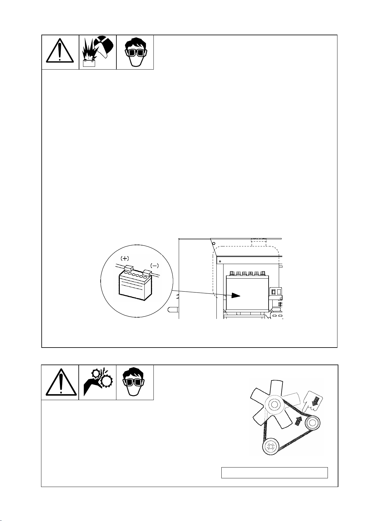
3-5 Battery Cable Connection
◆ Make sure the battery cables are properly connected to battery terminal
(+) and (-).
[ NOTE ]
[ NOTE ][ NOTE ]
[ NOTE ] : If the cable is connected incorrectly, damage to the electrical
parts will result soon.
◆ See the starter switch is “OFF” before connecting the battery cables.
[ NOTE ]
[ NOTE ][ NOTE ]
[ NOTE ] : Do not connect the cables to the battery terminal when the
starter switch is“ON”, because electric sparks will be produced.
This may injure the operator and cause damage to the machine's
electrical components.
[ NOTE ]
[ NOTE ][ NOTE ]
[ NOTE ] : It is recommended that a thin film of grease be applied to the
battery terminals to ensure a good connection and the prevention
of corrosion of the battery terminals. An insufficient sufficient
or poor connection may cause poor starting of the machine and
other malfunctions to occur.
◆
Connect (-) Cable Last.
3-6 Fan Belt
Check the belt for tension and looseness and adjust them as
required. Also, check that the belt has not been damaged and
immediately replace it if any abnormality is noted on the belt.
Perform the adjustment and replacement as directed in
the “Instruction Manual” provided by the Engine
Manufacturer.
Fan Belt : Parts No. Y 060 20 152 90

- 11 -
4-1 Engine Oil
Open air temp.(℃
)
-30 -20 -10 0 10 20 30
◆ The lubricating o
il used influences engine
performance, starting characteristic and
ultimately the life of the engine.
We recommend that the appropriate, good
quality, lubricating oil be used.
(1) We recommend that “CD class”
lubricating
oil be used ( API service grade ).
(2) We recommend the use of SAE10W-30 all season type of engine oil
viscosity. The viscosity of the oil to be used is dependent on the
external temperature. Refer to the table to select oil.
[ NOTE ]
[ NOTE ][ NOTE ]
[ NOTE ] : Do not pour in different kinds of oil as it will change the oil
quality which will have a detrimental effect on engine performance.
If you want to add in a different type of oil, you must first drain
the oil already in the engine completely.
(3) The total oil change capacity is 3.5 litters.
4-2 Engine Cooling Water
(1) Use only soft water for cooling water. For example, tap water that is
of good quality can be used.
(2) If the machine is to be used in cold areas, especially where there is a
risk of freezing, long-life, anti-freeze, coolant ( LLC ) should be used.
( This machine when delivered ex-factory, the radiator cooling water
contains 30 % long life coolant. )
[ NOTE ]
[ NOTE ][ NOTE ]
[ NOTE ] : The recommended ratio of LLC to be used is between 30 % - 50 %
range.
[ NOTE ]
[ NOTE ][ NOTE ]
[ NOTE ] : The following is the recommended of LLC to be used for below
mentioned temperature:
- 30 % : down to -10 ℃
- 40 % : down to -20 ℃
- 50 % : down to -30 ℃
[ NOTE ]
[ NOTE ][ NOTE ]
[ NOTE ] : The LLC should be changed at least every 2 years.
(3) The total cooling water capacity is 3.15 litters.
( This does not include the cooling water reserve tank. )
① For the proper use of LLC carefully follow the instructions given by
the LLC manufacturer.
② During cold periods and LLC is not used, the cooling water should be
drained, including the reserve tank cooling water before adding in the
LLC at the appropriate ratio in relation to the prevailing temperature.
- 12 -
4-3 Fuel
(1) Use ASTM No.2 Diesel Fuel
[ NOTE ]
[ NOTE ][ NOTE ]
[ NOTE ] : If other than the recommended type of fuel is used, it can
bring about a undesirable result to engine for its output
performance, length of life, etc.
(2) Use JIS special No.3 diesel fuel.
JIS No.2 Diesel Fuel : down to - 5 ℃
JIS Special No.3 Diesel Fuel : down to -25 ℃
(3) The Fuel tank capacity is 36 litters.
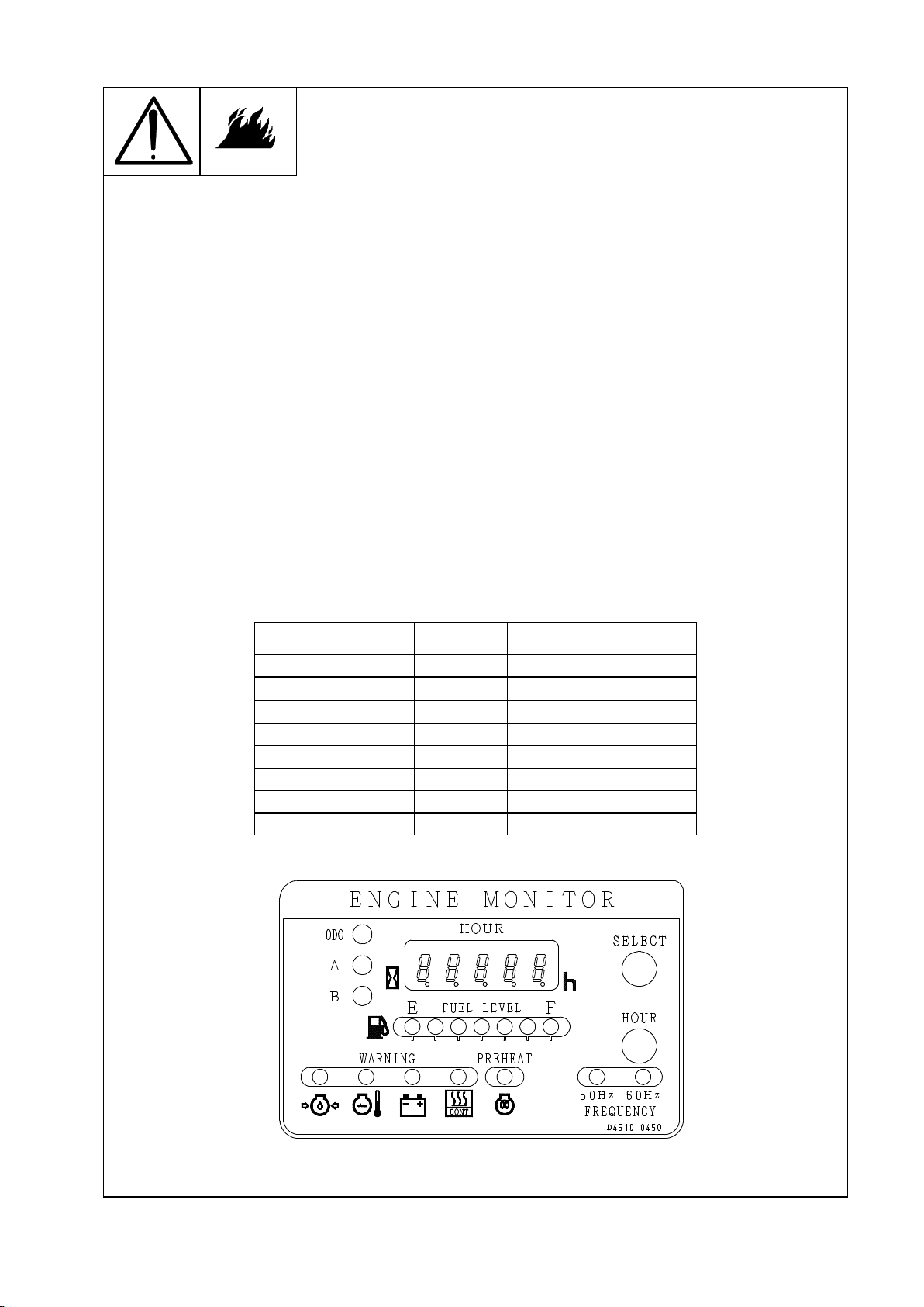
(1) Before starting the machine, check to see that fuel is sufficient by the engine
monitor.
(2) While fuel is full in the installed tank, all of green lamps are on. Numbers of lamps
decrease as remaining fuel amount decrease. Color of lamps also change from green
to red following decrease of remaining fuel amount. Fill fuel when only one lighting
lamp is left. A cor
relation between numbers of lighting lamps and remaining fuel amount
is roughly like the below chart.
The number of lamp
Lamp color
Fuel residual quantity
7 Green 32Full
6 Green 2832
5 Green 2428
4 Green 2024
3 Green 1620
2 Green 1316
1 Green 1013
1 Red 010
- 13 -
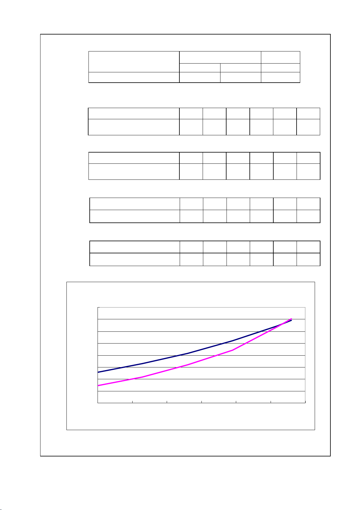
4-4 Fuel Consumption
(1) No Load
High Low
No Load
(3000min
-1
) (3600min
-1
) (2000min
-1
)
Fuel Consumption (L/h) 1.28 1.65 0.72
(2) Load
High[50Hz]
Amperes (A) 0 65 130 195 260 280
Fuel Consumption (L/h) 1.28 1.64 2.07 2.60 3.23 3.45
High[60Hz]
Amperes (A) 0 70 140 210 280 300
Fuel Consumption (L/h) 1.65 2.01 2.49 3.12 3.98 4.21
Variable[50Hz]
Amperes (A) 0 65 130 195 260 280
Fuel Consumption (L/h) 0.72 1.19 1.59 2.21 3.20 3.52
Variable[60Hz]
Amperes (A) 0 70 140 210 280 300
Fuel Consumption (L/h) 0.72 1.20 1.63 2.34 3.95 4.22
Fuel Consumption (50Hz)
Fuel Consumption (50Hz)Fuel Consumption (50Hz)
Fuel Consumption (50Hz)
0.00
0.50
1.00
1.50
2.00
2.50
3.00
3.50
4.00
0 50 100 150 200 250 300
DCWeld Amperes at 100% duty cycle [A]
Fuel Consumption [L/h]
High
HighHigh
High
Variable
VariableVariable
Variable

- 14 -
Fuel Consumption (60Hz)
Fuel Consumption (60Hz)Fuel Consumption (60Hz)
Fuel Consumption (60Hz)
0.00
0.50
1.00
1.50
2.00
2.50
3.00
3.50
4.00
4.50
0 50 100 150 200 250 300 350
DCWeld Amperes at 100% duty cycle [A]
Fuel Consumption [L/h]
High
HighHigh
High
Variable
VariableVariable
Variable

- 15 -
◆ Check the positions shown under before starting.
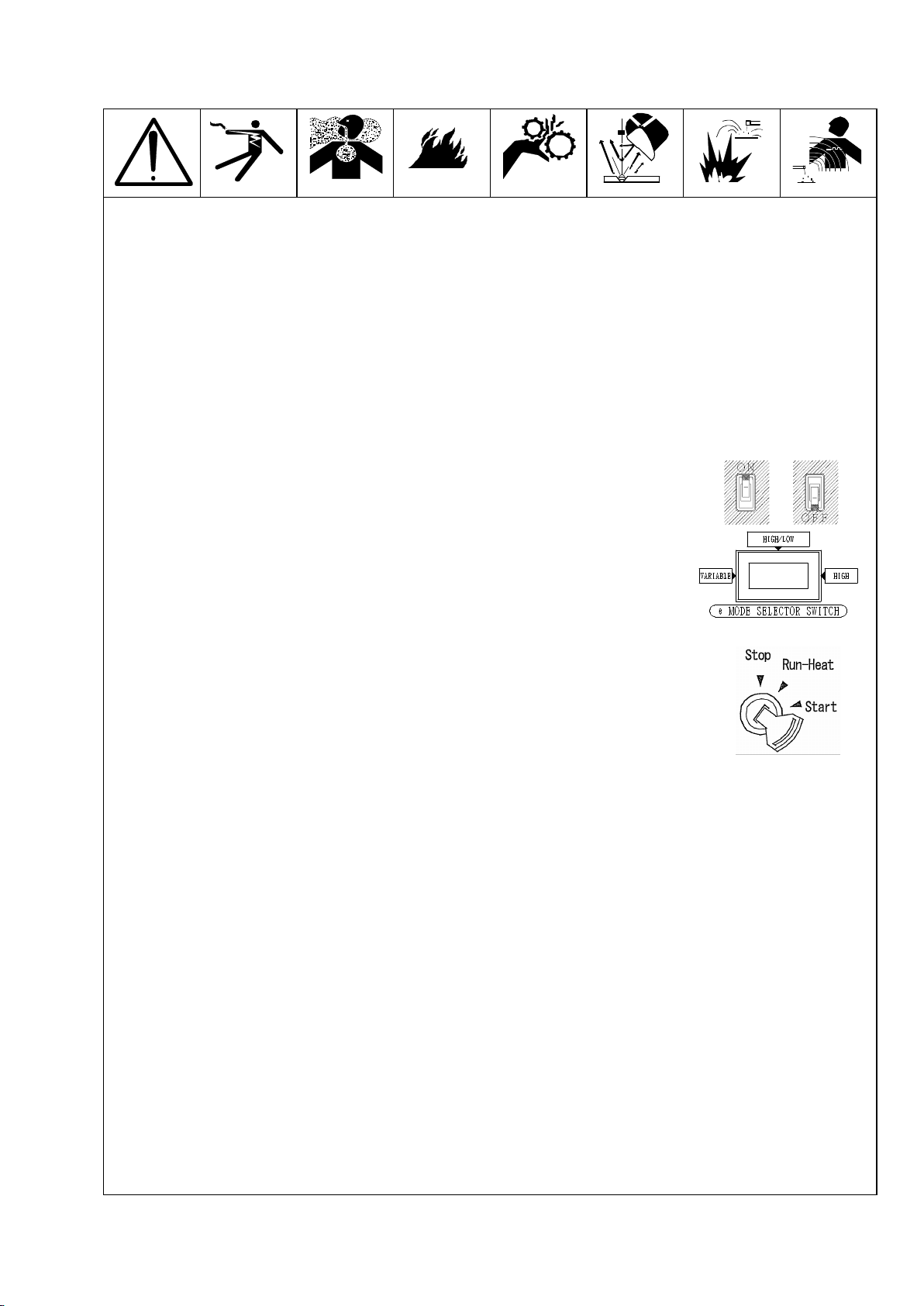
- 16 -
◆ Before starting the machine, the pre-starting safety checks must be completed.
In addition, do a general survey of the area surrounding the machine making
sure the area is safe, air vents of the machine are not blocked and the exhaust
can freely be discharged.
The machine can be started, once the people surrounding the machine have been
notified that the machine is going to be used.
[ NOTE ]
[ NOTE ][ NOTE ]
[ NOTE ] : In cold operating conditions, use suitable cooling water and
lubricating oil for improved starting and prevention of any
troubles. The battery must always be maintained at full
charging level.
(1) Check whether the breaker is at the “OFF” position.
(2) Turn the “e Mode Selector Switch” to select VARIABLE or HIGH/LOW.
(3) Insert the key into the “Starter Switch”. When turn the key to
the "RUN-Heat" position, the indicator lamp acts as a
"Oil indicator" and "Charge indicator". If the indicator lamp
don't come on, inspect the electric bulb of indicator lamp or
the fuse.
(4) Turn the key to the“Start”position to start the engine.
As soon as the engine starts, release the key where by the
key will automatically return to the “Run”position.
[ NOTE ]
[ NOTE ][ NOTE ]
[ NOTE ] : Key switch will automatically return to “Run-Heat” position
after the engine has started.
If the key switch did not return automatically, return it
manually to prevent damage to the starter.
[ NOTE ]
[ NOTE ][ NOTE ]
[ NOTE ] : During winter or when the surrounding air temperature is cold, in
situations where a load start is required, turn the key to the
“Pre-heat position”, you must wait until the engine indicator
lamp goes off.
(5) In situations where the sounds of the engine turning over cannot be heard in trying
to start the machine, repeat the starting procedure from the beginning in accordance
with the Operation Manual, after about 30 seconds.
If the machine fails to start despite repeating the starting procedure, there is obviously
some problem with the machine.
Therefore a thorough check is required ( e.g.: Fuel has run out, forgetting to turn
the fuel cock to the open position, excessive air in the fuel system and battery leakage )

- 17 -
(6) After the engine starts, let the machine idle 510 minutes to warm-up.
And the engine rotates high speed for a few seconds immediately after the engine starts,
if the “e Mode Selector Switch” is in VARIABLE or HIGH/LOW.
[ NOTE ]
[ NOTE ][ NOTE ]
[ NOTE ] : While the engine is operating, do not turn the starter switch on.
(7) Carefully check the engine for abnormal vibration ( noise ), oil leakage,
fuel leakage, cooling water leakage and air leakage. If the machine is operating
normally, set the “Circuit breaker”to the ON position in order to supply
electricity to the load.
(8) Do not have any of the doors of the machine open while operating. The main problems
with leaving the doors of the machine open during operating, are the effect on the internal
cooling air-flow of the machine and alien substances ( e.g. dust and dirt ) will be
drawn into the machine.
(9) After the engine in started, check to see that the oil pressure lamp and battery
charging lamp are off. If one of these lamps are on, check the machine after the engine
is turned off. (Refer to the Operation Manual for details)
(10) While the engine is operating, check the Hour Meter operating. When turn the key to
the “Start” position, the Hour Meter operating.

- 18 -
(1) Turn the load side's circuit breaker to the“OFF”position.
(2) Turn the circuit breaker on the machine to the“OFF”position and let
the engine idle for five minutes, so as to allow the engine to cool
down. After the five minutes idling period is over, turn the key to the
“OFF”position.
(3) Remove the key out of the starter switch. Make sure the key, when the
machine is not use, is kept in safe.
(4) Turn the fuel filter cock to the “Close”position.
(5) Disconnect the wiring and plug(s) from the AC Power connections.
(6) Make sure the machine is not exposed to moisture. It is important that
the machine be kept dry when not in use.
(7) To keep the machine in good working order, do not leave the machine
exposed to the elements and cover it using a sheet, when the machine
is not been used.
[ NOTE ]
[ NOTE ][ NOTE ]
[ NOTE ] : In the unlikely occurrence of the engine not stopping when the
key is turned to the “OFF”position, there is a way of
stopping the machine. Please refer to the following diagram
and explanation.
Turn the fuel filter cock to the “Close”position.
Closing the fuel filter cock cuts the supply of fuel to the
engine and the engine will take a few minutes to come to a stop.
This should only be done in case of an emergency.
Table of contents
Other Denyo Welding System manuals


Popular Welding System manuals by other brands


Lampert
Lampert PUK 3s professional operating instructions

SHARKS
SHARKS Super power IGBT 190A Instruction for operation and maintenance

widos
widos HRG 10 Working Instructions Translation

GYS
GYS KRONOS 250M manual

Kemppi
Kemppi MASTER MLS 1600 Operation instructions

Hobart Welding Products
Hobart Welding Products Champion Elite owner's manual