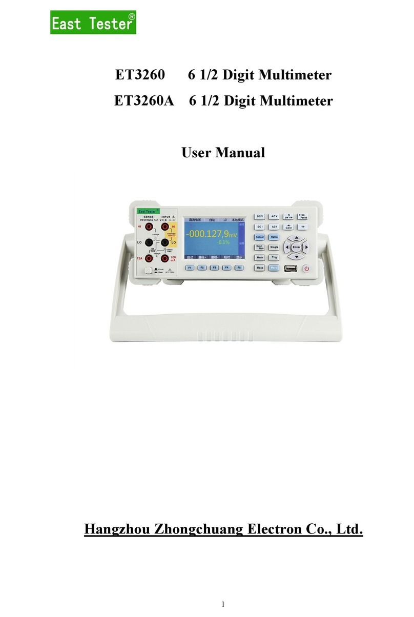
East Tester ET3240 User manual

ET3240
4%
Benchtop
Digital
Multimeter
ET3255
5%
Benchtop
Digital
Multimeter
User’s
Manual
Hangzhou
Zhongchuang
Electronics
Co.
Ltd.

Table
of
Contents
1
Safety
Precautions..……
2
Introduction.
Bite.
2.1
Main
features
:
2.2
General
features
3
Quick
reference.
Ee
3.1
check
the
accessories
of
the
produ
3.2
Appearance
of
the
front
pane
3.4
Keys
introductton…
…
…
34.1
Power
Switch
key.
3.4.2
Arrow
keys.…
3.4.3
Basic
measurement
function
keys.
3.4
4
Mathmatic
function
keys.
34.5
Additional
function
keys…
3.4.6
Second
function
key
combinatior
3.5
Rear
panel
introduction.…
3,6
Adjust
the
handle.
3.7
Tum
on
the
multimeter…
4
Basie
measurement
function
4.1
Voltage
measurement
…
……
4.1.1
DC
Voltage
measurement.
4.1.2
AC
voltage
measurement.
4.2
Current
measurement
_…
…
…
……
42.1
DC
eurrent
measurement.
4.2.2
AC
current
measurement…
4.3
Resistance
measurement.
ao
4.3.1
2-wire
resistance
measurement…
4.3.2
4-wire
resistance
measurement.
4
A
Frequency
measurement
and
period
measurement.
AA.
Frequency
measurement…
4.4
2
Pernod
measurement.
4.5
Diode
measurement
and
on-ofl
measurement.
4.5.1
Diode
measurement.
4.5.2
On-off
measurement
….
4.6
Capacitance
measurement
4.7
Duty
eycle
measurement.
5
Additional
measurement
function.
51
Statistics
5.2
MX+B.….
5.3
dB
and
dBm.
SAREL.
5.5
Pass/Fail.
SOM.
5.7
Data
storage
and
readbac!
5.8
Temperature.
…
6
System
settings.

6.1
Language
switch.
6.2
Buzzer
switch
6.3
Screen
brightness
adjustment.
6,4
Interface
style
selection…
7.1
Temperature.
8
Calibration.
8.1
DC
voltage
calibration.
8.2
AC
voltage
calibration.
8.3
DC
current
calibration…
84
AC
current
calibration.
8.5
Resistance
calibration…
8,6
Capacitance
calibration
9
Communication
Interface
…
10
Related software
installation
and
use.
LL
Maintenance
and
upkeep…
……
…
…
11.1
General
maintenance
and
repair.
112
Replace
the
fuse

5
V2
Digital
Multimeter
User
Manual
1
Safety
Precautions
To
avoid
personal
injury
and
prevent
damage
to
the
instrument,
be
sure
to
use
this
instrument
in
accordance
with
the
manual.Before
fully
understanding
and
meeting
the
following
warning,do
not
proceed
to
the
next
step.
Safety
ground:
Connect
the
power
cord
of
the
instrument
to
a
grounded
socket.
Make
sure
that
the
instrument
is
reltably
grounded,
Use
proper
fuse:
Please
use
only
fuscs
of
the
specified
type
and
rating.
Proper
use
of
lead
set:
Do
not
use
damaged
or
worn
test
lead
set.
When
using
probes,
the
finger
should
be
kept
behind
the
finger
protector
of
the
probe.
When
wiring,
you
should
connect
the
common
line
first
and
then
connect
the
charged
test
lead.
When
disconnecting,
disconnect
the
charged
test
lead
first.
IF
the
instrument
malfunctions,
do
not
use:
Its
protection
may
be
impaired,
do
not
install
substitute
parts
or
conduct
unauthorized
adjustment
of
the
instrument.
Please
return
the
instrument
for
repair
or
professional
inspection
to
ensure
their
safety
features.
Do
not
use
this
instrument
at
high
temperature,
or
environment
with
explosives
or
strong
electromagnetic
field.
Do
not
change
the
wiring
inside
the
instrument,
so
as
not
to
cause
damage
to
the
instrument
or
endanger
the
safety.
When
measuring,
you
must
select
the
correct
measurement
function
and
(he
measurement
range.
Before
the
function
range
is
switched,
disconnect
the
probe
and
the
circuit
under
test
to
prevent
damage
to
the
instrument.
Protect
limits:
Without
exceeding
the
protection
linnts,
the
protection
circuit
of
this
instrument
prevents
damage
to
the
instrument
and
shock
hazard.
To
ensure
the
safe
operation
of
the
instrument,
do
not
exceed
the
marked
Limits
for
protection
on
front
and
rear
panels.
IEC
measurement
type
H
overload
protection:
To
avoid
the
risk
of
electric
shock,
this
instrument
provides
overload
protection
for
the
mains
under
the
following
two
conditions.
1)
HI
and
LO
input
terminals
under
the
condition
of
the
measurement
type
Il
(as
described
below)
are
connected
to
mains.
2)
‘The
maximum
hine
voltage
of
mains
is
300
VAC.
In
order
to
avoid
blown
fuse
or
damage
to
the
meter,
be
sure
to
follow
these
tips
to
use
the
current
input
terminals.
1)
10
A
and
200mA
input
terminals
are
not
allowed
to
sitnultaneously
connect
to
the
current
measurement
circuit.
2)
Ifthe
effective
value
of
the
measured
current
AC
+
DC
15
withun
the
vange
from
200mA
to
10
A,
only
10A
and
LO
terminals
are
allowed
to
be
used
in
the
measurement.
3)
Before
performing
current
measurement,
be
sure
to
select
the
correct
current
input
terminal
according
to
the
expected
current
size.

5
1/2
Digital
Mulumeter
User
Manual
4)
The
current
input
to
the
terminal
10
A
must
not
exceed
TOA,
otherwise,
the
internal
fuse
inside
the
multimeter
will
blow;
and
the
current
input
to
200mA
terminal
must
not
exceed
5OOmA;
otherwise,
the
current
imput
fuse
on
the
rear
panel
will
blow.
Warning:
IEC
measurement
type
I
includes
the
electrical
device
one
of
whose
sockets
on
the
branch
circuit
is
connected
to
mains,
Such
devices
include
most
small
appliances,
test
equipment,
and
other
equipment
inserted
into
the
branch
socket.
The
voltage
higher
than
300
VAC
can
only
be
measured
in
the
circuit
with
the
mans
cut
off.
However,
there
is
transient
overvoltage
in
the
circuit
with
the
mains
cut
off
This
instrument
can
withstand
up
to
2500
Vpk
of
oecasional
transient
overvoltage
safely.
Do
not
use
this
instrument
to
measure
the
circuit
with
a
transtent
overvoltage
higher
than
(lus
level.
This
instrument
can
be
used
for
such
measurements:
HI
and
LO
inputs
are
connected
to
mains
of
such
devices
(up
to
300
VAC),
or
to
the
branch
outlet.
However,
the
HI
and
LO
inputs
terminals
of
this
instrument
cannot
be
connected
to
the
mains
in
the
permanently
installed
electrical
devices,
such
as
the
main
circuit-breaker
panel,
sub-panel
fuse
boxes,
or
permanently
wired
motors.
Such
devices
and
circuits
ument
for
overload
protection
can
easily
exceed
(he
limit
of
thus
ms
Environment
related
notes:
“This
instrument
complies
with
the
requirements
on
marking
under
WEEE
Directive
(2002/96
/
EC).
According
to
the
label
on
the
instrument
(see
below),
do
not
dispose
the
electrical
/
electronic
equipment
along
with
household
waste
together.
‘Thus
instrument
may
contain
substances
that
might
be
harmful
to
the
environment
or
human
healtir,
in
order
to
avoid
the
release
of
hazardous
substances
into
the
environment
or
harm
to
human
health,
we
recommend
the
use
of
appropriate
methods
to
recycle
thus
instrument
in
order
to
ensure
that
most
of
the
materials
are
reused
or
recyeled.
For
disposal
or
recycling
related
information,
please
contact
the
local
authorities.
EEE
Instrument
category:
According
to
Appendix
1
of
the
WEEE
Directive,
the
instrument
is
classified
as
a
"monitored
and
controlled
instrument’.
Signs
on
the
product:
The
following
signs
might
be
seen
on
the
instrument:
PA
A
/
Signal
ground
chassis
ground
High
voltage
Refer
to
Manual
Limited
warranty
and
liability.
‘The
company
1s
responsible
for
free
repaur
or
replacement
within
one
year
from
the
date
of
purchase,
but
does
not
include
damage
to
fuse
and
damage
caused
by
human
factors.
2
Introduction
XXXXSS
is
a
5:
digits,
240000
counting,
dual
digital
benchtop
true-RMS
multimeter
The
STM32
chip
and
external
double
integral
AD
used
by
this
benchtop
multimeter
providing
accurate
measurement

5
1/2
Digital
Multimeter
User
Manual
and
stable
performance.
3.5
inch
320
*
480
high
resolution
TFT
LCD
screen
makes
a
clear
reading,
rich
display,
and
a
good
visual
effects.
This
benchtop
multimeter
are
powered
by
electricity
and
provide
full-function,
full-range
overload
protection.
Fresh
and
simple
design
with
excellent
performance
makes
them
an
ideal
choice
for
electricians,
electronics
enthusiasts,
engineers
and
colleges
and
universities.
2.1
Main
features
®
5
digits,
240000
counting,
3.5-inch
320
*
480
TFT
LCD.
Dual
parameter
display:
it
can
display
two
parameters
of
the
same
input
signal.
Measurement
display
rate:
FAST
(7
times
/
second),
MID
(5
times
/
sec),
SLOW
(2
times
/
sec).
‘Trigger
mode:
Automatic
trigger,
single
trigger,
external
trigger.
Range
switching
mode:
Auto
/
Manual.
12
basic
measurement
functions:
AC
and
DC
voltage,
AC
and
DC
current,
two-wire
/
four-wire
resistance,
period
/
frequency,
diode,
on-off
test,
capacitance,
duty
cycle.
®
DCV
basic
accuracy:
0,01%.
®
Additional
functions:
Data
hold,
data
storage,
data
readback.
®
Mathematical
functions:
MX+B/MAX/MIN/Average/dBB/dBm/Rel/Limits
Compare/
Statistics/%a/
IX
®
Temperature:
Thermocouple:
K/N/R/S/T/B/F/I/WRe325/WRe526,
Thenmal
resistance.
PT
100
/
PTS0/Cul00
/
Cu50.
®
Built-in
(hermocouple
cold
junction
temperature
compensation.
Support
Manual
or
Auto
temperature
compensation
mode
keys
can
be
locked.
Open
calibration
function
Square
wave
output
Provide
system
settings,
can
configure
the
language,
buzzer,
sereen
brightness,
interface
display
style.
Communication
Interface:
Standard:
USB
Device.
RS232;
Optional.
USB
Host,
GPIB,
LAN,
WIFI,
Bluetooth.
®
Support
SCPI
protocol.
2.2
General
features
Power
supply
voltage:
220V
AC
10%,HOV
AC
4
10%,45-6SHz.
Working
environment::
0-40'C,
relative
humidity
=80%.
Storage
environment:
-10-50'C,
relative
humidity
<80%
Dimensions:
265mm*
10Smm*30Smm(width*height*depth).
.
Weight:
2.3kg.
ene
3
Quick
reference
3.1
check
the
accessories
of
the
product
Confirm
the
following
accessories
of
the
multimeter,
among
which
the
optional
accessories
are
delivered
if'only
ordered.
[Fany
items
are
missing,
please
contact
the
nearest
sales
office.
Standard
accessories:
Optional
accessories:
A
ir
of
proe:
ï
ì
RS232
senal
lime.
A
efiieesi
8
USB
cable
A
double
end
three-wire
power
line.
8
Two
back:
fi
GPIB
cable.
wo
up
power
fuse,
par
User
manual.

5
1/2
Digstal
Multumeter
User
Manual
Standard
and
optional
function/information
of
communication
interface:
Standard
communication
interface
USB
Device,
RS232
Optional
communication
interface
GPIB,
USB
Host,
LAN,
WIFI,
Bluctooth
Standard
function
Square
wave
output,
Extemal
trigger
Table
3-1
Standard/optional
functions
and
communication
interfaces.
3.2
Appearance
of
the
front
panel
Front
panel
as
shown
in
Figure
3-
1,
the
regional
description
see
Table
3-2
2
3
ete
al.
2.
00000
«
100,
0
Figure
3-1
Front
panel
diagram
Description
fl
Measurement
ternimal
of
multimeter.
2
Display
screen.
3
Basic
measurement
function
keys.
4
Arrow
keys.
5
5
Mathematical
function
keys.
6
Additional
function
keys,
7_{Powerkey
Table
3-2
Area
description
of
front
panel
3.3
Display
interface
AUTO
TRI
ALTO
2V
Slow
Local
el
Figure
3-2
Interface
of
the
display
NO.
Description
1
Displays
the
name
of
the
current
measurement
function.
B
Display
Tngger
Mode
Auto
Trigger,
Single
Trigger,
External
Trigger.
3
Display
only
m
automatic
mode,
indicate
the
currently
range

5
1/2
Digital
Multimeter
User
Manual
4
Main
display
area.
Displays
the
current
measured
value.
5
Secondary
display
arca.
Displays
additional
information
about
the
current
É
measured
value.
6
‘The
configuration
area
of
the
current
measurement
function.
Display
range,
measurement
speed,
additional
functions,
local
/
remote
information.
Figure
3-3
Description
of
the
interface
area
3.4
Keys
introduction
3.4.1
Power
Switch
key
bran
On
/
Off
the
main
power.
3.4.2
Arrow
keys
Ee
Enzer
Up
arrow
key.
Y_Down
arrow
key.
Enter
key.
<
Id
Left
arrow
key.
Right arrow
key
3.4.3
Basic
measurement
function
keys
DC
voltage
measurement
key.
AC
voltage
measurement
key
DC
current
measurement
key.
AC
current
measurement
key.
2-wire
/
4-wire
resistance
measurement
key.
Capacitance
measurement
key.
Frequency
/
period
measurement
key.
Diode
/
on-oll
measurement
key.
3.4.4
Mathmatic
function
keys
Statics
key.
In
the
voltage
(DC
voltage,
AC
voltage),
current
(DC
current,
AC
current),
resistance
(two-wire
resistance,
four-wire
resistance),
frequency,
period,
capacitance
measurement
function,press
the
key
to
turn
on
the
statistical
operation.(
Contains
the
maximum,
minimum,
average,
standard
deviation,
number
of
samples,
range.)
MX
1
B
function
key
combination.
In
the
voltage
(DC
voltage,
AC
voltage),
current
(DC
current,
AC
current),
resistance
(two-wire
resistance,
four-wire
resistance),
frequency,
petod,
capacitance
measurement
function,
press
the
key
combination
to
turn
on
the
MX
+
B
measurement
function.
Press
the
combination
key
again
to
exit
the
MX
+
B
function.
dB
measurement
key.
In
the
voltage
(DC
voltage,
AC
voltage)
measurement
function,

5
1/2
Digital
Mulumeter
User
Manual
press
the
key,
the
dB
value
of
the
measured
value
will
be
displayed
on
the
secondary
display
area.
The
reference
voltage
can
be
modified,
the
default
is
1
V.
dBm
measurement
key.
In
the
voltage
(DC
voltage,
AC
voltage)
measurement
function,
press
the
key,
the
dBm
value
of
the
measured
value
will
be
displayed
on
the
secondary
display
area.
The
reference
resistance
can
be
modified,
the
default
is
6000.
Relative
value
measurement
key.
In
the
voltage
(DC
voltage,
AC
voltage),
current
(DC
current,
AC
current),
resistance
(two-wire
resistance,
four-wire
resistance),
frequency,
period,
capacitance
measurement
function,
press
the
key,
the
measured
value
will
be
subtracted
from
the
relative
value
in
the
secondary
display
area
and
displayed
mm
the
main
display.
le
the
main
value
—
the
measured
value
-
the
relative
value.
Relative
value
can
be
modified.
3.4.5
Additional
function
keys
u
tek
Square
wave
output
key.
Press
the
key,
a
amplitude
fixed,
frequency
adjustable
square
wave
will
be
output
from
the
rear
panel.
wan
un]
Duty
cycle
measurement
key
Press
the
key
to
turn
on
the
duty
cycle
measurement
function.
ar
zo)
Automatic
key.
In
manual
range
mode,
press
the
key
to
switch
to
auto
range.
In
external
trigger
/
single
trigger
mode,
press
the
key
to
change
the
trigger
made
to
auto
trigger.
TRIG
an
|
Single
trigger
key.
Press
the
key
to
change
the
multimeter
measurement
mode
to
single
trigger.
Each
time
the
key
is
pressed,
the
meter
measures
once
and
displays
a
reading
Er
SME
Save
key.
Press
the
key
to
save
the
relevant
information
of
the
current
measured
value;
press
the
key
again
to
exit
the
data
save
function.
IEA
ee
Data
read
back
key.
Press
this
key
to
enter
the
data
readback
function.
Press
any
of
the
basic
measurement
function
keys
to
exit
the
data
readback
function.
The
data
readback
function
displays
relevant
information
about
the
measured
values
that
have
been
stored.
Press
(he
up
/
down
arrow
key
to
select
the
measured
values
for a
specific
sequence
number.
mr
ee
|
System
settings
key.
Press
the
key
to
view
the
instrument
model,
serial
number,
version
number,
but
also
can
set
the
language,
switch
buzzer,
adjust
the
screen
brightness,
switch
the
interface
display
style.
3.4.6
Second
function
key
combination
wa
van
|
Reading
hold
function
key
combination.
Press
the
key
combination,
the
instrument
readings
remain
unchanged,
press
the
key
combination
again
to
exit
the
reading
hold
function.
j
U
Mee
AC
#
DC
measurement
function
key
combination
Press
the
key
combination
to
start
AC
+
DC
signal
measurement,
press
the
key
combination
again
to
exit
AC
+
DC
measurement
Fametion,
mie
ml
External
trigger
function
key
combination.
Press
the
key
combination
to
turn
on

5
1/2
Digital
Multimeter
User
Manual
the
external
trigger
measurement
mode.
In
this
mode,
when
the
external
trigger
terminal
enters
a
negative
pulse,
the
meter
measures
once
and
displays
a
reading.
cal
wmo
|
Calibration
function
key
combination.
In
the
voltage
(DC
voltage,
AC
voltage),
current
(DC
current,
AC
current),
resistance
(two-wirc
resistance,
four-wire
resistance),
capacitance
measurement
function,
press
the
key
combination
to
enter
the
corresponding
calibration
function,
Press
any
of
the
basic
measurement
function
keys
to
exit
the
calibration
function.
Limit
comparison
function
key
combination.
In
the
voltage
(DC
voltage,
AC
voltage)
measurement
function,
press
the
key
combination
to
turn
on
the
Lint
comparison
function.
The
Limit
comparison
value
can
be
modified.
EXIT
2e
|
Exit
kev.
Press
this
key
to
switch
from
the
current
measurement
function
to
the
basic
measurement
function
before
the
last
function
switch.
The
temperature
measurement
function
key
combination.
Press
the
key
combination
to
turn
on
the
temperature
measurement
function.
Depending
on
the
type
of
temperature
sensor
used,
press
the
up
/
down
/
lefl
/
right
arrow
key
to
select
the
corresponding
temperature
sensor
type
[or
temperature
measurement.
Hon
de
System
help
key
combination.
In
the
voltage
(DC
voltage,
AC
voltage),
current
ij
(DC
current,
AC
current),
resistance
(two-wire
resistance,
four-wire
resistance),
frequency.
peiod,
capacitance
measurement
function,
press
the
key
combination
to
view
the
system
help
information.
3.5
Rear
panel
introduction
USB
Device
interface
Square
wave
output
port.
External
trigger
measurement
port.
Current
input
fuse
0.SA/
250V.
Table
3-3
Description
of
the
rear
panel
3.6
Adjust
the
handle
‘To
adjust
the
handle
of
the
digital
multimeter,
hold
the
handle
on
both
sides
of
the
body
and
pull
it
outward.
Then
rotate
the
handle
to
the
desired
position.
The
operation
method
is
shown
in
Figure
3-5.
The
multimeter
can
be
placed
as
shown
in
Figure
3-6,
and
the
location
of
the
carrying
as
shown
in
Figure
3-7,

5
1/2
Digital
Multimeter
User
Manual
in
Y
Figure
3-5
Adjust
handle
Figure
3-6
Working
position
Figure
3-7
Carrying
position
3.7
Turn
on
the
multimeter
Connect
the
AC
power
supply
1
Multimeter
power
supply
can
choose
110V
or
220V,
adjust
the
power
supply
voltage
selector
on
the
rear
panel
of
the
multimeter
according
to
the
supply
voltage.
2.
Use
the
provided
power
cord
to
connect
the
multimeter
to
AC
power.
Start
the
multimeter
Press
the
power
swithch
key.
If
the
instrument
does
not
start
normally,
follow
the
steps
below
to
check:
1
Check
ifthe
power
cord
is
in
good
contact
2
Check
if
the
power
switch
key
is
pressed.
3.
Check
if
the
power
fuse
has
been
blown,
replace
the
fuse,
if
necessary.
4.
Mthe
above
check
is
correct,
the
instrument
has
not
yet
started,
please
contact
the
relevant
departments.
4
Basic
measurement
function
Warning:
1)
Before
measuring,
make
sure
the
wiring
is
correct.
In
order
to
avoid
damage
to
the
multimeter,
and
possible
personal
safety
hazards,
do
not
measure
the
voltage
beyond
the
rated
mput
limit.
2)
After
the
voltage
up
to
1000
VDC
is
measured,
it
is
better
to
wait
for
about
2
minutes,
and
then
conduct
the
low
voltage
measurement
with
the
resolution
rate
1
to
10
uV.
3)
After
using
the
A
input
terminal
for
measuring
high
currents,
it
is
better
to
wait
for
about
10
minutes,
and
then
conduct
the
low-level
DC
measurements
(volts,
amps,
or
ohms)
in
order
to
achieve
accuracy.
The
reason
1s
that
measuring
the
thermal
voltage
generated
by
the
high
current
may
cause
errors
in
the
low-level
measurements.
4)
After
the
completion
of
all
measurements,
disconnect
the
probe
and
the
circuit
under
test
and
remove
the
probe
from
the
input
terminal
of
(he
mstrument.
5)
When
measuring
the
high
voltage
and
high
current,
pay
special
attention
to
safety.
4.1
Voltage
measurement
4.1.1
DC
Voltage
measurement
1.
Press
to
select
the
DC
voltage
measurement
function.
The
measurement
interface
is
shown
in
Figure
4-
1
2.
Connect
the
red
and
black
test
leads
to
the
corresponding
input
terminals
as
shown
in
Figure
4-2.
3,
Press
the
up
/
down
arrow
key
to
manually
select
the
appropriate
range
or
select
the
auto
range
Cal
mode
by
pressing
«wel,
press
the
left
/
right
arrow
key
to
select
the
appropriate
measurement
speed.
4.
Start
the
measurement.

5
1/2
Digital
Multimeter
User
Manual
©
UI
IRE
1.
00000
50.0
%
AUTO
AUTO
Local
Figure
4-
1
Measurement
interface
Figure
4-2
Wiring
method
Note:
1)
The
measured
voltage
value
is
displayed
in
the
main
display
area,
and
the
value
in
the
secondary
display
area
represents
the
ratio
of
the
current
measured
value
to
the
full
scale
valuc
2)
Full
range
input
protection:
1000V
DC.
4.1.2
AC
voltage
measurement
L
Press
&
to
select
the
AC
voltage
measurement
function.
The
measurement
interface
is
shown
in
Figure
4-
3
2_Connect
the
red
and
black
test
leads
to
the
corresponding
input
terminals
as
shown
in
Figurc
4-4.
3.
Press
the
up
/
down
arrow
key
to
manually
select
the
appropriate
range
or
select
the
auto
range
CML
Î
mode
by
pressing
—_
70,
press
the
left
/
right
arrow
key
to
select
the
appropriate
me:
urement
speed.
4.
Start
the
measurement
®
AUTO
IRL
1.
00000
»
1.
OOOk
Hz
AUTO
2V
AUTO
Slow
Local
Figure
4-
3
Measurement
interface
Figure
4-4
Wiring
method
Note:
1)
The
measured
voltage
value
is
displayed
in
the
main
display
area,
and
the
value
in
the
secondary
display
area
represents
the
measured
frequency
of
the
current
input
signal.
2)
To
ensure
accuracy.
the
input
value
should
be
greater
than
10%
of
the
range,
and
not
higher
than
the
re
3)
Full
range
input
protection:
750V
RMS
ge
of
90%
4.2
Current
measurement
Note:
1)
The
fuses
used
for
low
current
measurement
is
0.5A
250V
and
10A
250V
for
high
current
measurement.
2}
Try
to
avoid
high
current
for
a
longs
time
continuous
measurement,
pay
attention
to
the
protection
of
personal
safety.

5
1/2
Digital
Mulumeter
User
Manual
3)
Low
current
measurement
in
the
automatic
mode
does
not
switch
to
a
higher
current
range,
please
pay
attention
to
the
tmely
adjustment
of
the
input
terminal
wiring.
4)
High
current
measurement
in
the
automatic
mode
does
not
switch
to
a
lower
current
range,
please
pay
attention
to
the
timely
adjustment
of
the
input
terminal
wiring.
4.2.1
DC
current
measurement
8
d
5
E
5
ES
L.
Press
Ed
to
select
the
DC
current
measurement
function,
The
measurement
interface
is
shown
in
ligure
4-5.
ALTO.
TRI
1.
00000
50.0
«%
Local
Figure
4-5
Measurement
interface
Note:
‘The
measured
current
value
is
displayed
in
the
main
display
area,
and
the
value
in
the
secondary
display
area
represents
the
ratio
of
the
current
measured
value
to
the
full
scale
valuc.
2
Choose
different
test
terminals
according
to
the
measurement
level.
See
Figure
4-6
for
current
of
200mA
and
below,
and
connect
the
red
and
black
test
leads
respectively
to
the
proper
input
terminals.
See
Figure
4-7
for
current
from
200mA
to
10A,
and
connect
the red
and
black
test
leads
respectively
to
the
proper
input
terminals.
3.
Press
the
up
/
down
arrow
key
to
manually
select
the
appropriate
range
or
select
the
auto
range
ca
made
by
pressing
—_
A
|
press
the
left
/
right
arrow
key
to
select
the
appropriate
measurement
speed.
A.
Start
the
measurement
SENBE
INPUT
4
ZENE.
INEUT
&
vt
ELEN
ÖÖ:
tele}
Figure
4-6
Wiring
method
for
low
current
Figure
4-7
Wiring
method
for
high
current
measurement
measurement
4.2.2
AC
current
measurement
1
Press
]
to
select
the
AC
current
measurement
function.
The
measurement
interface
is
shown
in
Figure
4-8.

5
1/2
Digital
Multimeter
User
Manual
MAO
ARE
1.
00000
,
1.
000
Figure
4-8
Measurement
interface
Note:
‘The
measured
current
value
is
displayed
in
the
main
display
area,
and
the
value
in
the
secondary
display
arca
represents
the
measured
frequency
of
the
current
input
signal
2.
Choose
different
test
terminals
according
to
the
measurement
level.
See
Figure
4-9
for
current
of
200mA
and
below,
and
connect
the
red
and
black
test
leads
respectively
to
the
proper
input
terminals.
See
Figure
4-
10
for
current
from
200mA
to
LOA,
and
connect
the
red
and
black
test
leads
respectively
to
the
proper
input
terminals.
3.
Press
the
up
/
down
arrow
key
to
manually
select
the
appropriate
range
or
select
the
auto
range
a
mode
by
pressing
_
#7,
press
the
left
/
right
arrow
key
to
select
the
appropriate
measurement
speed.
4.
Start
the
measurement
mor
mon,
ej
Figure
4-9
Wiring
method
for
low
current
Figure
4-
10
Wiring
method
for
high
current
measurement
measurement
4.3
Resistance
measurement
Note:
1)
Before
measuring
the
resistance,
disconnect
the
circuit
power
and
discharge
all
high-voltage
capacitors
to
avoid
damages
to
the
multimeter
2)
In
the
case
of
2-wire
resistance
measurement,
the
relative
function
can
be
considered
in
order
to
eliminate
the
error
caused
by
the
lead
resistance.
3)
200MO
range
readings
beating
is
a
normal
phenomenon.
4.3.1
2-wire
resistance
measurement
L
Press
“5
to
select
the
2-wire
resistance
measurement
function
by
default.
The
measurement
interface
is
shown
in
Figure
4-
11
2.
Connect
the
red
and
black
test
leads
to
the
corresponding
input
terminals
as
shown
in
Figure
4-12
3.
Press
the
up
/
down
arrow
key
to
manually
select
the
appropriate
range
or
select
the
auto
range

5
1/2
Digital
Multimeter
User
Manual
ca,
mode
by
pressing
the
—_
A
|
press
the
left/
right
arrow
key
to
select
the
appropriate
measurement
speed.
4.
Start
the
measurement.
®
AUTO
ERL
1.
00000,»
50.0
%
Local
Figure
4-
11
Measurement
interface
Figure
4-
12
Wiring
method
Note:
The
measured
resistance
value
is
displayed
in
the
main
display
arca,
and
the
value
in
the
secondary
display
area
represents
the
ratio
of
the
current
measured
value
to
the
full
scale
value.
4.3.2
4-wire
resistance
measurement
1.
In
the
2-wire
resistance
measurement
function,
press
*
#_again
to
select
the
4-wire
resistance
measurement
function.
The
measurement
interface
is
shown
in
Figure
4-
13.
2
Connect
the
red
and
black
test
leads
to
the
corresponding
input
terminals
as
shown
in
Figure
d- 14
3.
Press
the
up
/
down
arrow
key
to
manually
select
the
appropriate
range
or
select
the
auto
range
CN!
mode
by
pressing
—
4!
press
the
left
/
right
arrow
key
to
select
the
appropriate
measurement
speed.
4
Start
the
measurement
en
ee
1.
00000,
even
50.0
%
en
OO
hes
AUTÓ
Slow
Las,
bate
Figure
4-
13
Measurement
interface
Figure
4-
14
Wiring
method
Note:
‘The
measured
resistance
value
15
displayed
in
the
main
display
area,
and
the
value
in
the
secondary
display
arca
represents
the
ratio
of
the
current
measured
value
to
the
full
scale
valuc.
4.4
Frequency
measurement
and
period
measurement
4.4.1
Frequency
measurement
1.
Press
*_to
select
the
frequency
measurement
function
by
default.
The
measurement
interface
is
shown
in
Figure
4-
15.

5
1/2
Digstal
Multimeter
User
Manual
2.
Connect
the
red
and
black
test
leads
to
the
corresponding
input
terminals
as
shown
in
Figure
4-16.
3.
Press
the
up
/
down
arrow
key
to
manually
select
the
appropriate
range
or
select
the
auto
range
cat
mode
by
pressing
—_
A”
4.
Start
the
measurement
van
tee
1
0
0000
E
:
kH
He
AUTO
2kHiz
ad
AUTO
Slów
on
ee)
Figure
4-
15
Measurement
interface
Figure
4-
16
Winng
method
4.4.2
Period
measurement
1.
Inthe
frequency
measurement
function,
pres:
agan
to
select
the
period
measurement
function.
The
measurement
interface
is
shown
in
Figure
4-
17.
2.
Connect
the
red
and
black
test
leads
to
the
corresponding
input
terminals
as
shown
in
Figure
4-18.
3
Press
the
up
/
down
arrow
key
to
manually
select
the
appropriate
range
or
select
the
auto
range
cht
mode
by
pressing
—
AT
A.
Start
the
measurement.
PERIOD
—
WAN
SAANE
ERE
1.
00000.
Local
en
wi
Figure
4-
17
Measurement
interface
Figure
4-
18
Wining
method
4.5
Diode
measurement
and
on-off
measurement
Fest
conditions:
the
forward
DC
current
is
approximately
LmA,
and
the
reverse
DC
voltage
no
higher
than
3V.
4.5.1
Diode
measurement
1
Press
=
to
select
the
diode
measurement
function
by
default.
"OPEN"
is
displayed
when
the
voltage
value
1s
higher
than
the
measuring
threshold,
and
the
measured
voltage
1s
displayed
when
the
measured
value
is
below
the
measuring
threshold.
The
diode
threshold
voltage
is
3.2V
The
measurement
interface
is
shown
in
Figure
4-
19,
2.
Connect
the
red
and
black
test
leads
to
the
corresponding
input
tenninals
as
4-20.
shown
in
Figure

5
1/2
Digital
Mulumeter
User
Manual
3_
Start
the
measurement
DIC
®
AIO
TRE
0.
57110
v
sense
aw
EUT
4
vase
Figure
4-
19
Measurement
interface
Figure
4-
20
Wiring
method
4.5.2
On-off
measurement
L_In
the
diode
measurement
function,
p!
*_again
to
select
the
on-off
measurement.
The
measurement
interface
ís
shown
mn
Figure
4-21
2.
Connect
the red
and
black
test
leads
to
the
corresponding
input
terminals
as
shown
1m
[Figure
4-22.
3.
Start
the
measurement
CONTAKT
0.
10000,
sense
meute
an
vom
Figure
4-
21
Measurement
interface
Figure
4-22
Wiring
method
Note:
1)
When
the
measured
resistance
15
greater
than
2kO,
display
"OPEN",
less
than
2KO,
display
readings
2)
When
the
measured
value
is
lower
than
the
set
short-circuit
resistance
value,
the
buzzer
sounds.
The
short-circuit
resistance
value
defaults
to
300,
3)
The
short-circuit
resistance
value
can
be
set
by
pressing
the
Enter
key
in
the
on-off
measurement
interface
and
using
the up,
down,
left
and
right
direction
keys
to
set
between
O
and
2kO.
4.6
Capacitance
measurement
1,
Press
Be
to
select
the
capacitance
measurement
function.
The
measurement
interf
shown
in
ligure
4-23
2.
Connect
the
red
and
black
test
leads
to
the
corresponding
input
terminals
as
shown
in
Figure
4-24,
3.
Press
the
up
/
down
arrow
key
to
manually
select
the
appropriate
range
or
select
the
auto
range
|
mode
by
pressing
—
1,
press
the
left
/
right
arrow
key
to
select
the
appropriate
measurement
speed.
4
Start
the
measurement.

5
1/2
Digital
Multumeter
User
Manual
UTO
IRL
1.
000,
BENSE
WIT
4
À
ied
vand
50.0
«%
AUIO
nf
Local
Figure
4-23
Measurement
interface
Figure
4-24
Wiring
method
Note:
4)
The
measured
capacitance
value
is
displayed
in
the
main
display
area,
and
the
value
in
the
secondary
displayed
area
represents
the
ratio
of
the
current
measured
value
to
the
full
scale
value.
5)
When
measuring
large
capacitance,
(he
measurement
time
is
slightly
longer
due
to
the
charge
and
discharge
of
the
capacitor.
4.7
Duty
cycle
measurement
En!
1.
Press
—
wi
to
select
the
duty
cycle
measurement
function.
The
measurement
interface
is
shown
in
Figure
4-
25,
2.
Connect
the red
and
black
test
leads
to
the
corresponding
input
terminals
as
shown
in
Figure
4-26.
3.
Start
the
measurement
®
AUTO
TRE
50.
0
Figure
4-25
Measurement
interface
Figure
4-26
Wiring
method
5
Additional
measurement
function
5.1
Statistics
In
the
voltage
(DC
voltage,
AC
voltag:
(DC
current,
AC
current),
resistance
(2-wire
resistance,
4-wire
resistance),
frequency,
period,
capacitance
measurement
function.
Press
Ì_to
turn
on
the
statistical
operation,
as
shown
in
Figure
5-
L.
Press
the
key
again
to
exit
statistical
operation.

5
1/2
Digital
Multimeter
User
Manual
©
AIO
TRD
099.
Max
:
100,
001
M
pan
:000,
002kG
Z00KE
Slow
Stats
Clear Losal
Figure
S-
|
Statistic
measurement
interface
Note:
1)
When
the
statistical
function
is
turned
on,
the
maximum,
minimum,
average,
he
standard
deviation,
the
number
of
samples,
and
the
range{the
subtract
between
the
maximum
value
and
the
minimum
value)
is
displayed
sunultaneously.
2)
To
re-statistics,
you
can
press
the
clear
sofikey.
5.2
MX+B
In
the
voltage
(DC
voltage,
AC
voltage),
current
(DC
current,
AC
current),
resistance
(2-wire
resistance,
4-wire
resistance),
frequency,
period,
capacitance
measurement
function:
Press
key
to
select
the
MX
+
B
function,
as
shown
in
Figure
5-2.
Press
the
key
again
to
exit
the
MX
|
B
fumetion.
Note:
1)
Formula:
Y=M
*
X
+
B,
where
Y
is
the
value
displayed
in
the
secondary
display
arca.
M
isa
monomial
coefficient,
B
ís
a
constant.
2)
In
the
interface
shown
in
Figure
5-2,
press
the
Enter
key
to
call
up
the
M
value
modification
shown
in
Figure
5-3,
The
value
of
M
can
be
modified
by
the
use
of
up
/
down
/
left
/
right
arrow
key.
3)
In
the
mterface
shown
in
Figure
5-3,
press
the
Enter
key
to
call
up
the
B
value
modification
interface.
The
value
of
B
can
be
modified
by
the
use
of up
/
down
/
left
/
night
arrow
key.
©
UND
ARL
©
Ate
el
1.
20000
»
Y:
1.
20000
AUTO
2V
interface,
1.
20000
M:+001.
000
AUTO
AUTO
Slow
…
MX
+
B
AUTO Stow
MX
+
B
Loeal
Figure
5-2
MX
|
B
measurement
interface
Figure
5-3
M
value
modified
interface
5.3
dB
and
dBm
In
the
voltage
(DC
voltage,
AC
voltage
)
measurement
function:
1
Press
&
4_ta
select
the
dB
measurement
function,
as
shown
in
Figure
5-4.
Press
f
ik
|
agam
to
exit
the
dB
measurement
function.
2
Press
id
]
to
select
the
dBm
measurement
function,
as
shown
in
Figure
5-6,
Press
É
ad

5
1/2
Digital
Multimeter
User
Manual
ement
function.
3_In
the
interface
shown
in
Figure
5-4,
press
the
Enter
key
to
call
up
the
dl
reference
voltage
setting
interface.
The
up/down
/
left
/
right
array
key
can
be
used
to
modify
the
value
of
the
dB
reference
voltage,
as
shown
in
Figure
5-5,
4
In
the
interface
shown
mn
Figure
5-6,
press
the
Enter
key
to
call
up
the
dBm
reference
voltage
setting
interface.
The
up
/
down/
left
/
right
array
key
can
be
used
to
modify
the
value
of
the
dBm
shown
in
Figure
5-7
agan
to
exit
the
dm
meas
reference
voltage,
DCV
@
ACTOR
2.
00000
»
6.
O2UB
@
MTOE
1.
00000
10.
0O4Bm
AUTO
2V
AUTO Slow Slow
da
10083:
Local
Figure
5-6
dBm
measurement
interface
AUTO
ERE
1.
20000
‚
1.
00000
‚
1.000
v
1000
AUTO
AUTO
2V
ALITO
Slow
Local
AUTO
Slow
dim
Figure
5-5
dB
reference
voltage
modified
Figure
5-7
dBm
reference
resistance
modified
interface
interface
Note:
1)
dBm=
10*log10
[(Vauca'/Ree)/0.001
},
where
Vaca
is
the
measured
value
displayed
in
the
main
display
area
(n
the
case
of
a
millivolt
range,
Vat
is
the
measured
value
divided
by
1000),
Rrer
is
thee
reference:
ince
and
defaults
to
6000,
2)
dB
=
20*logtO(Vmer/
Vres),
where
Vea
is
the
measured
value
displayed
in
the
main
display
arca
(in-the
case
of
a
millivolt
range,
Vnaca
ts
the
measured
value
divided
by
1000),
Vuarts
the
reference
voltage
and
defaults
to
1
V.
5.4
REL
In
the
voltage
(DC
voltage,
AC
voltage),
current
(DC
current,
AC
current),
resistance
(2-wire
resistance,
4-wire
resistance),
frequency,
period,
capacitance
measurement
function:
Press
®
|
to
select
the
REL
function,
as
shown
in
Figure
5-8.
Press
|
d
agam
to
exit
the
REL
function.
In
the
interface
of
Figure
5-8,
press
the
Enter
key
to
call
up
the
relative
value
setting
interface.
The
up
/
down
/
left
/
right
arrow
key
can
be
used
to
modify
the
relative
value,
as
shown
m
ligure
5-9
This manual suits for next models
1
Table of contents
Other East Tester Multimeter manuals