1
Introduction
WARNINGS
The Southwire 11060S multimeter measures AC and DC voltage
and current, resistance, temperature, capacitance, frequency and
duty cycle. It also tests continuity and diodes. Readings are
displayed on a large backlit LCD. This meter is fully tested and
calibrated and, with proper use, will provide many years of reliable
service.
• Read, understand and follow the Safety Rules and Operating
Instructions in this manual before using this meter.
• The meter’s safety features may not protect the user if not
used in accordance to the manufacturer’s instructions.
• Ensure that the test leads are fully seated in the input jacks and
keep fingers away from the metal probe tips when taking
measurements.
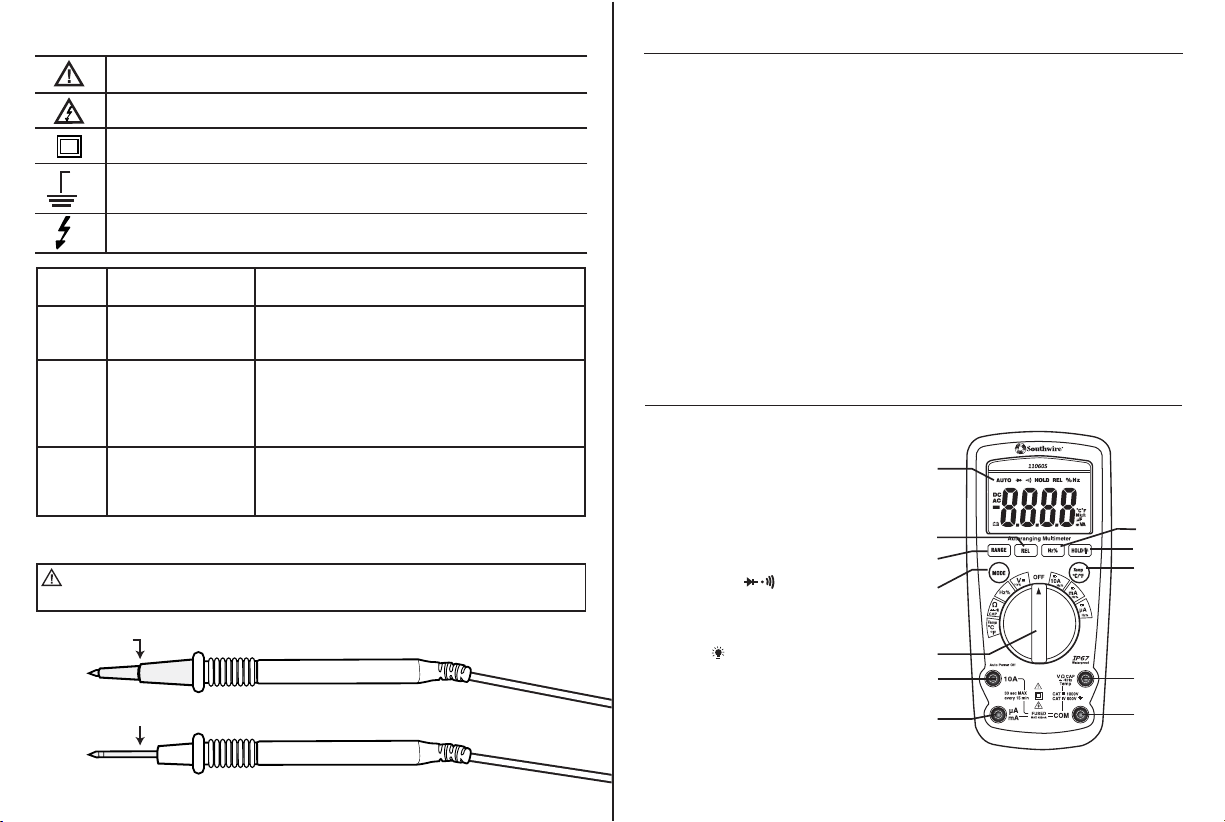
• Confirm operation of test leads by checking resistance.
The resistance reading should be 0.5Ω or less when the red
and black probe tips are touching each other.
• Use only UL listed test leads with the proper safety category
rating.
• Before changing functions using the selector switch, always
disconnect the test leads from the circuit under test.
• Comply with all safety codes. Use approved personal protective
equipment when working near live electrical circuits -
particularly with regard to arc-flash potential.
• Use caution on live circuits. Voltages above 30 V AC RMS,
42 V AC peak, or 60 V DC pose a shock hazard.
• Do not use meter or test leads if they appear damaged.
• Verify meter’s operation by measuring a known voltage.
• Do not use the meter in wet or damp environments or during
electrical storms.
• Do not use the meter near explosive vapors, dust or gasses.
• When replacing the battery or fuses, be sure to secure the back
cover panel and battery compartment door firmly to maintain
the waterproof and dust proof integrity of the meter. Loose or
overtightened screws, or an improperly seated o-ring may
compromise the meter's water and dust ingress protection.
2
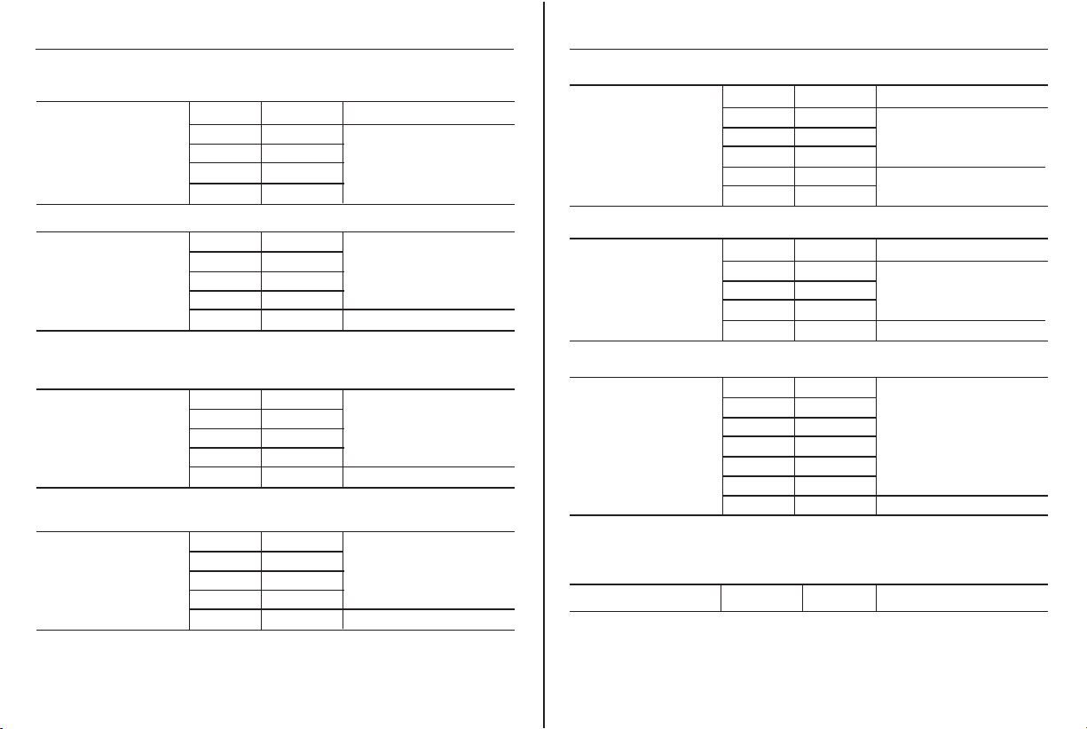
Input Limits
Function Maximum Input
Voltage AC or DC
µA Current AC or DC
mA Current AC or DC
10A AC or DC
Resistance, Continuity,
Diode Test, Frequency, Duty Cycle
Temperature
1000VAC rms, 1000VDC
4000µA AC rms, 4000µA DC ; 1000VAC rms, 1000VDC
400mA AC rms, 400mA DC ; 1000VAC rms, 1000VDC
10A AC rms, 10A DC ; 1000VAC rms, 1000VDC
1000VAC rms, 1000VDC
1000VAC rms, 1000VDC
• Do not apply voltage or current that exceeds the meter’s
maximum rated input limits.
General Specifications
• Replace the battery as soon as the low battery warning appears.
Insulation: Class II, Double Insulation
Overvoltage category: CAT IV 600V, CAT III 1000V UL 61010-1 standards
Maximum voltage between any
terminal and earth ground: 1000V DC/AC RMS
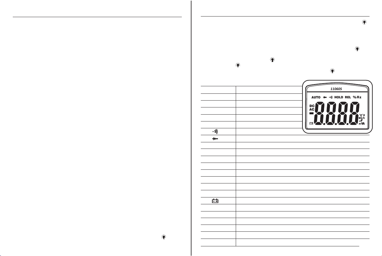
Display: 4000 count LCD display
Polarity: Automatic, (-) negative polarity indication
Over-range: “OL” mark indication.
Low battery indication: A battery “ ”symbol is displayed when the
battery voltage drops below the operating level
Measurement rate: 2 times per second nominal
Auto power off: Meter automatically shuts down after approx.
30 minutes of inactivity
Operating environment: 41°F to 104°F (5°C to 40°C) at < 80% relative humidity
Storage temperature: -4°F to 140°F (-20°C to 60°C) at < 80% relative humidity
Relative humidity: <80%
Altitude: 7000ft (2000m)
Pollution degree: 2
Power: One 9V battery, NEDA 1604, IEC 6F22 or equivalent
Dimensions/Weight: 6.8” x 3” x 2”/Approx. 0.83lb) (172 x 77 x 52mm/Approx. 375g)
IP67: Dust protected and water protected
(immersion up to 1m for up to 30 minutes)
Safety: The instrument complies with IEC/EN 61010-1, 2nd edition