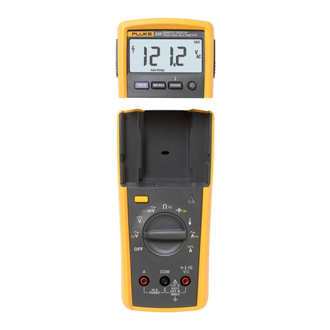
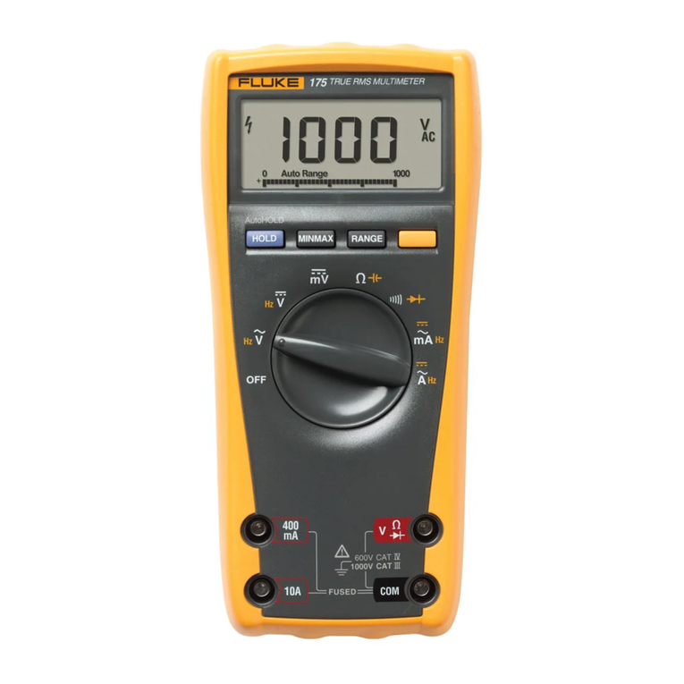
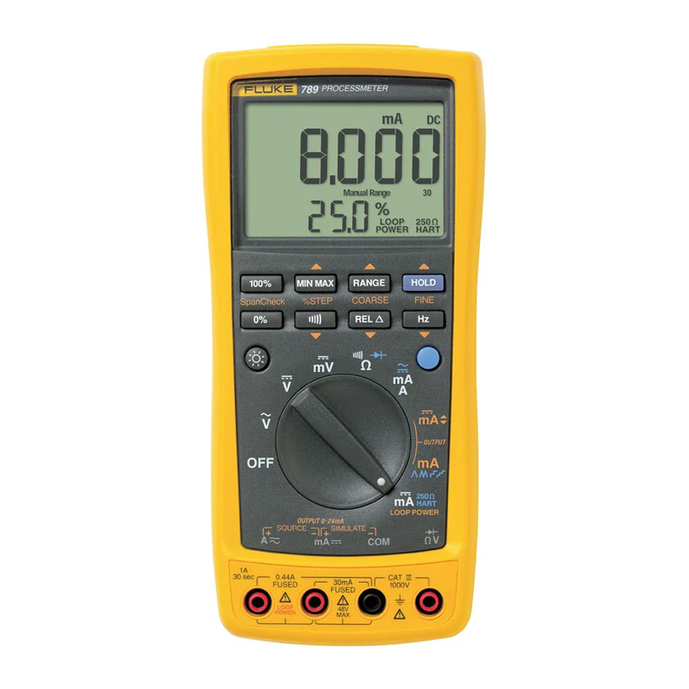
Fluke 8050A User manual

P/N 530907
October
1979 Rev 2 7
/84
®1984,
John
Fluke Mfg. Co., Inc. All rights reserved.
Lithe
in U.S.A.
8050A
Digital
Multimeter
Instruction Manual
IFLUKE:I
======®

WARRANTY
Notwithstanding
any provision of any agreement the
following
warranty is exclusive:
The
JOHN
FLUKE MFG. CO., INC., warrants each instrument
it
manufactures to be free from defects in material and
workmanship
under
normal
use and service
for
theperiod of1-yearfrom date
of
purchase. This warrantyextends
only
to the
original
purchaser.
This
warranty shall not apply
to
fuses, disposable batteries (rechargeable
type
batteries are
warranted
for
90-days),
or
any
product
or
parts
which
have been subject to misuse, neglect, accident,
or
abnormal
conditions
of
operations.
In the event
of
failure
of
a
product
covered by this warranty,
John
Fluke Mfg. Co., Inc., will repair and calibrate
an
instrument returned to
an
authorized Service Facility
within
1year
of
the original purchase; provided the warrantor's
examination discloses
to
its satisfaction that the
product
was defective. The warrantor may, at its optioh, replace the
product
in lieu
of
repair. With regard
to
a_ny
instrument returned
within
1year
of
the original purchase, said repairs
or
replacement will be made without charge.
If
the failure has been caused by misuse, neglect, accident,
or
abnormal
conditions
of
operations, repairs
will
be billed at a nominal cost. In such case,
an
estimate
will
be submitted before
work is started, if requested.
THE FOREGOING WARRANTY IS IN LIEU OF ALL OTHER WARRANTIES, EXPRESS OR IMPLIED,
INCLUDING
BUT
NOT
LIMITED TO ANY IMPLIED WARRANTY
OF
MERCHANTABILITY, FITNESS,
OR ADEQUACY FOR ANY PARTICULAR PURPOSE OR USE.
JOHN
FLUKE MFG. CO., INC.,
SHALL
NOT
BE
LIABLE
FOR ANY SPECIAL,
INCIDENTAL,
OR
CONSEQUENTIAL
DA~AGES,
WHETHER IN
CONTRACT,
TORT,
OR
OTHERWISE.
If
any failure occurs, the following steps should be taken:
1.
Notify
the
JOHN
FLUKE MFG. CO., INC.,
or
nearest Service facility, giving full details
of
the
difficulty,
and
include
the model number,
type
number, and serial number. On receipt of this information, service data,
or
shipping
instructions
will be forwarded to you.
2.
On receipt
of
the shipping instructions, forward the instrument, transportation prepaid. Repairs will be
made at the Service Facility and the
instrument
returned, transportation prepaid.
SHIPPING TO MANUFACTURER FOR REPAIR
OR
ADJUSTMENT
All shipments of
JOHN
FLUKE MFG. CO., INC., instruments
should
be made via United Parcel Service
or
"BestWay'
..
prepaid. The instrument
should
be shipped in the original
packing
carton;
or
if
it is not available, use any suitable
container
that
is rigidand
of
adequatesize.
If
asubstitute
container
is used, theinstrument
should
be wrapped in paper
and
surrounded
with at least four inches
of
excelsior
or
similar shock-absorbing material.
CLAIM FOR DAMAGE IN SHIPMENT
TO
ORIGINAL PURCHASER
The
instrument
shoula
be
thoroughly
inspected immediately
upon
original delivery to purchaser. All material in the
container should be
checked
against theenclosed
packing
list. The
manufacturer
will notbe responsible
for
shortages
against
the
packing sheet unless notified immediately. Ifthe
instrument
is damaged in anyway, aclaim should be filed
with the carrier immediately. (To obtain a
quotation
to
repair
shipment
damage, contact the nearest FlukeTechnical
Center.) Final claim and negotiations with the carrier must be completed by the customer.
The
JOHN
FLUKE MFG. CO., INC,
will
be
happy
to
answer all
applications
or
use questions,
which
will enhance
your
use
of
this instrument. Please address
your
requests
or
correspondence to:
JOHN
FLUKE MFG. CO., INC., P.O. BOX
C9090, EVERETT,
WASHINGTON
98206,
ATTN:
Sales Dept.
For
European Customers: Fluke (Holland) B.V., P.O. Box
5053, 5004 EB, Tilburg,
The
Netl1erlands.
*For European customers,
Air
Freight prepaid.
John Fluke Mfg. Co., Inc., P.O. Box C9090, Everett, Washington 98206
Rev.
6/81
Table of Contents
SECTION TITLE PAGE
1 INTRODUCTION AND SPECIFICATIONS
............................
1-1
1-1.
INTRODUCTION
............................................
1-1
1-4.
OPTIONS AND ACCESSORIES
...............................
1-1
1-5.
SPECIFICATIONS
...........................................
1-1
2 OPERATION
.......................................................
2-1
2-1.
INTRODUCTION
............................................
2-1
2-3.
SETTING UP YOUR INSTRUMENT
..........................
2-1
2-4.
Unpacking
.................................................
2-1
2-8.
AC Line Voltage Requirements
...............................
2-1
2-10. Fuse Replacement
...........................................
2-1
2-13. FRONT PANEL FEATURES
...............•..................
2-2
2-15.
Display
....................................................
2-2
2-18.
SIGNAL INPUT LIMITS
.....................................
2-2
2-20.
OPERATING TECHNIQUES
..................................
2-3
2-22.
AC/DC
Voltage
(V)
.........................................
2-3
2-24.
AC/
DC
Current (mA) . . . . . . . . . . . . . . . . . . . . . . . . . . . . . . . . . . . . . . .
2-3
2-26.
Resistance (il)
..............................................
2-7
2-28.
Conductance (S =
lil)
.......................................
2-7
2-30.
Diode Test
.................................................
2-7
2-32.
Relative (RELATIVE)
.......................................
2-7
2-36.
Decibel (dB)
................................................
2-11
2-38.
INITIAL CHECKOUT PROCEDURE
..........................
2-12
2-41.
APPLICATIONS
.............................................
2-12
2-43.
DC
Voltage Measurement
....................................
2-12
2-51.
Current Measurement
.......................................
2-13
2-56.
Resistance Measurement
.....................................
2-13
2-62.
Conductance Measurement
...................................
2-14
2-80.
Relative Measurement
.......................................
2-16
2-84.
AC Voltage and Current Measurement
.........................
2-16
3 THEORY OF OPERATION
...........................................
3-1
3-1.
INTRODUCTION
............................................
3-1
3-3.
FUNCTIONAL DESCRIPTION
...............................
3-1
3-5.
CIRCUIT DESCRIPTION
.....................................
3-1
(continued on page
ii)
-

TABLE
OF
CONTENTS, continued
SECTION TITLE
PAGE
3-7.
A/D
Converter
.............................................
3-1
3-18.
Microcomputer . . . . . . . . . . . . . . . . . . . . . . . . . . . . . . . . . . . . . . . . . . . . .
3-2
3-20.
Signal Conditioning . . . . . . . . . . . . . . . . . . . . . . . . . . . . . . . . . . . . . . . . .
3-6
3-31.
True-RMS Converter
..
. . . . . . . . . . . . . . . . . . . . . . . .
..
. .
..
. . . .
....
3-8
3-38. Touch-Hold Circuit
.........................................
3-8
3-40.
Voltage Protection . . . . . . . . . . . . . . . . . . . . . . . . . . . . . . . . . . . . . . . . . .
3-8
3-43.
Current Protection . . . . . . . . . . . . . . . . . . . . . . . . . . . . . . . . . . . . . . . . . .
3-8
4 MAINTENANCE . .. . . .. .. ..... . .... . ... . . . .... ... . . ... ... . . . . . .. . .. .
4-1
4-1. INTRODUCTION
............................................
4-1
4-4. SERVICE INFORMATION
...................................
4-1
4-7. GENERAL INFORMATION
..................................
4-1
4-9.
Interior Access
..............................................
4-1
4-24. dB Reference Impedance Power-Up Setting . . . . . . . . . . . . . . . . . . . . .
4-4
4-26. Cleaning . . . . . . . . . . . . . . . . . . . . . . . . . . . . . . . . . . . . . . . . . . . . . . . . . . .
4-5
4-28. PERFORMANCE TESTS . . . . . . . . . . . . . . . . . . . . . . . . . . . . . . . . . . . . .
4-5
4-30. Initial Procedures . . . . . . . . . . . . . . . . . . . . . . . . . . . . . . . . . . . . . . . . . . .
4-5
4-32. Display Test
................................................
4-5
4-34. Linear Voltage Test
.........................................
4-6
4-36. dB Voltage Test
.............................................
4-6
4-38. Current Test
................................................
4-7
4-40. Resistance and Conductance Tests
.............................
4-7
4-42. CALIBRATION ADJUSTMENTS . . . . . . . . . . . . . . . . . . . . . . . . . . . . .
4-8
4-44.
DC
Calibration . . . . . . . . . . . . . . . . . . . . . . . . . . . . . . . . . . . . . . . . . . . . .
4-8
4-46. AC Calibration . . . . . . . . . . . . . . . . . . . . . . . . . . . . . . . . . . . . . . . . . . . . .
4-8
4-48. Jumper Selection . . . . . . . . . . . . . . . . . . . . . . . . . . . . . . . . . . . . . . . . . . . .
4-8
4-57. TROUBLESHOOTING
.......................................
4-12
5 LIST
OF
REPLACEABLE
PARTS
. . .. . .. . . . .. ..... . . . ... .... . . .. ... ..
5-1
TABLE
OF
CONTENTS
......................................
5-1
5-1.
INTRODUCTION
............................................
5-2
5-3.
PARTS ORDERING INFORMATION
.........................
5-2
6 OPTIONS AND ACCESSORIES ... .. .. .. . . .. ..... . . . ... .... . . . ... ...
6-1
TABLE
OF
CONTENTS
......................................
6-1
INTRODUCTION . . . . . . . . . . . . . . . . . . . . . . . . . . . . . . . . . . . . . . . . . . . .
6-2
ACCESSORIES
..............................................
600-1
OPTIONS
...................................................
601-1
7 SCHEMATIC DIAGRAMS
...........................................
7-1
TABLE
OF
CONTENTS
......................................
7-1
APPENDIX A . . .. . . .. .. .. .. . .. . .. . .. . .. .. .. . . .... . . .. .. . ... . ... . . . ..
A-1
ii

-
TABLE
1-1.
1-2.
2-1.
2-2.
3-1.
4-1.
4-2.
4-3.
44.
4-5.
4-6.
4-7.
4-8.
4-9.
4-10.
4-11.
4-12.
4-13.
List of Tables
TITLE
8050A Accessories
................................................
.
8050A Specifications
..............................................
.
8050A Controls, Indicators, and Connectors
..........................
.
Maximum
Input
Signal Limits
......................................
.
AC
Buffer Gains
..................................................
.
Required
Test
Equipment
..........................................
.
dB Impedance Selection
...........................................
.
Display
Test
.....................................................
.
Linear Voltage Test
...............................................
.
dB Voltage Test
..................................................
.
Current
Test
.....................................................
.
Resistance
and
Conductance Tests
..................................
.
DC
Calibration
...................................................
.
AC
Calibration
...................................................
.
U5
Jumper
Positions
..............................................
.
U33
Jumper
Positions
.............................................
.
Test Points
.......................................................
.
Troubleshooting Guide
............................................
.
iii/iv
PAGE
1-2
1-2
2-3
2-5
3-8
4-2
4-4
4-5
4-6
4-7
4-7
4-8
4-10
4-10
4-11
4-12
4-13
4-14

-
FIGURE
Frontispiece
1-1.
2-1.
2-2.
2-3.
2-4.
2-5.
2-6.
2-7.
2-8.
2-9.
2-10.
2-11.
2-12.
2-13.
2-14.
2-15.
2-16.
2-17.
3-1.
3-2.
3-3.
3-4.
3-5.
3-6.
4-1.
4-2.
List of Figures
TITLE
8050A Digital Multimeter
..........................................
.
8050A Dimensions
................................................
.
Controls, Indicators, and Connectors
................................
.
Liquid Crystal Display
.............................................
.
AC/
DC
Voltage Operation
.........................................
.
AC/DC
Current Operation
.........................................
.
Resistance Operation
..............................................
.
Conductance Operation
............................................
.
Diode Test Operation
.............................................
.
Relative Operation
.......
.-
........................................
.
dB Voltage Operation
.............................................
.
Circuit Loading Error
.............................................
.
Calculating Burden Voltage
Error
...................................
.
Transistor Beta Test Fixture
........................................
.
dB Circuit Gain
or
Loss Measurements
..............................
.
Waveform Comparisons
...........................................
.
Crest Factor
.....................................................
.
Total RMS Value
.................................................
.
Measuring Amplifier Bandwidth
•....................................
8050A Functional Block Diagram
...................................
.
A/D
Converter
...................................................
.
A/D
Converter Waveforms
........................................
.
Microcomputer Simplified Block Diagram
...........................
.
Signal Conditioning
...............................................
.
RMS Converter
..................................................
.
Display PCB Access
...............................................
.
Calibration Adjustment Locations
...................................
.
v
PAGE
Vl
1-6
2-2
2-4
2-5
2-6
2-7
2-8
2-9
2-10
2-11
2-13
2-14
2-15
2-17
2-18
2-19
2-19
2-20
3-3
3-4
3-5
3-6
3-7
3-9
4-3
4-9

8050A Digital Multimeter
vi

Section 1
Introduction and Specifications
1-1. INTRODUCTION
1-2.
Your JohnFluke Model8050A is a portable bench-
type digital multimeter
(D
MM) with a 4-1/2 digit liquid
crystal display (LCD). The 8050A has all the following
industry-standard features:
• Voltage measurements from
10
µV
to
IOOOV
deand
IO
mV
to 750V true-rms
ac.
• Current measurements from I0 nA to
2A
de and I0
µA
to
2A
true-rms ac.
• Resistance measurements from
IO
mil
to 20MO.
The 8050A also has severalspecial measurementfeatures.
These special features include the following:
•
•
•
•
Conductance measurements up to 100,000 MO.
Voltage measurements
in
decibels, that can be
referenced to I
of
16
user selected reference
impedances.
Resistance ranges that supply enough voltage to
turn
on a
PN
junction
to allow diodes
and
transistors to be tested.
The ability to store any input signal as an offset or
relative reference value.
•
•
•
Automatic polarity indication
and
overrange
indication.
Protection from overloads and protection from
transients
of
up to 6 kV,
IO
microseconds.
Dual-slope integration
a/
d conversion to ensure
noise-free measurements.
• Long term calibration stability (I year).
1-3.
The 8050A
is
warranted for a period of one year
upon
shipment
of
the instrument to the original
purchaser. Conditions
of
the warranty are given
at
the
front
of
this manual. The8050A
is
typicallypowered from
ac line voltages but may be powered by the optional
rechargeable battery.
1-4. OPTIONS
and
ACCESSORIES
l-5. The use
of
the 8050A can
be
enhanced
by
the
accessories available for this instrument. The accessories
are listed in Table
1-1.
This instrument can
be
ordered
with
the
Option
8050A-O l
Rechargeable
Battery.
Detailed information on options
and
accessories is
contained
in
Section 6
of
this manual.
1-6. SPECIFICATIONS
1-
7.
Specifications for the 8050A are listed in Table
1-2.
Specifications for the Option
8050A-Ol
Rechargeable
Battery and other accessory specifications are given in
Section 6
of
this manual.
1-1

INTRODUCTION
SPECIFICATIONS
MODEL
C86
Y8205
M00-200-611
M00-200-612
M00-200-613
80T-H
80T-150C
80T-150F
801-600
ELECTRICAL
Table 1-1. 8050A Accessories
DESCRIPTION MODEL DESCRIPTION
Ruggedized Carrying Case 80J-10 Current Shunt
Soft Carrying Case
BOK-6
High Voltage Probe
Offset Mounting Kit 80K-40 High Voltage Probe
Center Mounting Kit 83-RF
RF
Probe
Dual Mounting Kit 85-RF
RF
Probe
Touch-Hold Probe Y8100 DC/AC Current Probe
Temperature Probe, Celsius
Y8101
AC Current Transformer
Temperature Probe, Fahrenheit
Y8134
Deluxe Test Lead Set (safety designed)
Current Transformer
Y8140
Slim-Flex Test Leads
Table 1-2. 8050A Specifications
The electrical specifications given apply for
an
operating tem-
perature
of
18°C to 28°C (64.4°
Fto
82.4°
F),
relative humidityupto
90%,
and a 1-year calibration cycle.
Functions . .. . . .. . .. . .. .. . . .. . .. . . . .. . . .. . DC volts, AC volts (linear and dB), DC current,
AC
current,
resistance, diode test, conductance, relative.
DC Voltage
RANGE RESOLUTION ACCURACY for
1-Year
±200 mV
10µV
±2V
100µV
±20V 1 mV ±(0.03%
of
reading
+2
digits).
±200V 10
mV
±1000V
100mV
INPUT IMPEDANCE .. .. . . .. . .. .. .. . .. . .
10
MO in parallel with <100
pF,
all ranges.
NORMAL MODE REJECTION RATIO .. . >60 dB at
60
Hz
or
50
Hz.
COMMON MODE REJECTION RATIO . ..
>90
dB at
de,
50
Hz or
60
Hz
(1
kO
unbalanced)
(>120 dB available on request)
COMMON MODE VOLTAGE (MAXIMUM)
500V
de or peak ac
RESPONSE TIME TO
RATED ACCURACY 1 second maximum
MAXIMUM INPUT .. . .. . . . .. . .. . .. .. . . .. 1000V de
or
peak ac continuous (less than
10
seconds duration on
both the
200
mV
and
2V
ranges).
*DC voltages can also
be
measured using the dB mode with
.01
dB resolution between
5%
of
range and full range.
1-2

INTRODUCTION
SPECIFICATIONS
Table 1-2.
80SOA
Specifications
(cont)
AC Volts (True RMS Responding,
AC
Coupled)
VOLTAGE READOUT ACCURACY .. . .. .
±(%of
reading+
number
of
digits), between
5%
of
range and full
range.
INPUT RESOLUTION
VOLTAGE RANGE 20
Hz**
45 Hz 1 kHz 10 kHz 20 kHz 50 kHz
10
mV-
200 mV
lOµV
200mV
O.lV
· 2V lOOµV 2V
1%+10
.5%+10
1%+10
5%+30
lV
-20V 1 mV 20V I
lOV -200V
lOmV
200V '
lOOV -750V lOOmV 750V
**Typically
3 to 5 digits
of
rattle will be observed
at
full
scale
at
20
Hz.
RESOLUTION . ... . .. . .. . .. .. .. . . .. . .. . .
0.01
dB from
5%
of
scale
to
full scale;
0.1
dB from 1-5%
of
scale, 1dB
below 1
%
of
scale
VOLT -Hz PRODUCT
EXTENDED dB SENSITIVITY
10
7
max (200V
max@
50 kHz)
Typically -72 dB (6000 Ref) ±1 dB
to
10 kHz
EXTENDED FREQUENCY RESPONSE .. Typically -3 dB at 200 kHz
COMMON MODE REJECTION
RATIO
(1
kn
unbalance)
>60
dB at 50 Hz
or
60 Hz
CREST FACTOR RANGE Waveforms with a Peak/RMS ratio
of
1
:1
to
3:1
at full scale,
increasing
down
range
INPUT IMPEDANCE .. ... . .. . . .. . . •. . . .. 10 MO in parallel with
<100
pF
MAXIMUM INPUT VOLTAGE . .. . . .. . .. . 750V rms
or
1000V peak continuous (less than 10 seconds duration
on both
the
200 mV and 2V ranges),
not
to
exceed the volt-hertz
product
of
10
7
RESPONSE TIME .. . . ... . .. . . .. . . .. .. . . 2 seconds maximum
within
a range
REFERENCE IMPEDANCES . . .. .. . .. •. . Sixteen user-selectable impedance reference levels are provided
to
reference a OdBm, 1 mW level (500, 750, 930, 1100, 1250, 1350,
1son.
2son. 3000.
soon.
6000, soon, 9000, 10000. 12000),and an
80
impedance reference level is provided
to
reference a0dBWlevel.
NOTE:
On
request, the
NOT
SPECIFIED portion
of
the JOOV-750V Range can be
extended
to the Volt-Hertz product
of
1
O"!
dB Ranges
INPUT
VOLTAGE
0.77 mV -2 mV
2
mV-2V
O.lV-
2V
lV
-20V
lOV -200V
lOOV
-750V
dBm
(600!1
REF)
-60
to
-52
-52
to
+8
-18
to
+8
+2
to
+28
+22
to
+48
+42
to
+60
ACCURACY: from
5%
of
range
to full
scale,
1-year
RANGE
20Hz
45Hz
lkHz
lOkHz
20kHz
200
mV*
0.5 dBm
200
mV*
2V ±o.25dBm ±0.15 dBm
±o.25dBm
20V
'
200V
I
750V
*When
200
mV range
is
selected the 8050A autoranges
for
best accuracy
for
2V
inputs
and
less.
50 kHz
1-3

INTRODUCTION
SPECIFICATIONS
1-4
Table 1-2.
BOSOA
Specifications (cont)
DC Current
RANGE RESOLUTION ACCURACY for 1-Year BURDEN VOLTAGE
200µA
0.01
µA
2mA
0.1
µA
±(0.3% of reading+ 2 digits 0.3V
max
20mA
1
µA
200 mA
10µA
2000 mA
100µA
0.9V
max
OVERLOAD PROTECTION (ac/dc) .. . .. . 2A/250V fuse in series with 3A/600V fuse (for high energysources)
AC Current (True RMS Responding, AC Coupled)
INPUT RESOLUTION RANGE 20
Hz**
45
Hz
2 kHz
10
kHz 20 kHz BURDEN
CURRENT VOLTAGE
10µA
·
200µA
0.01
µA
200µA
I
100µA-2mA
0.1
µA
2mA
I
I
1
mA-20mA
1
µA
20mA
2%+10
1%+10
2%+10
0.3V
rms
max
I
10mA
-200
mA
10µA
200mA
100
mA
· 2000
mA
100µA
2000mA
0.9V
rms
max
**Typically
3
to
5 digits
of
rattle will
be
observed
at
full
scale
at
20
Hz.
CREST FACTOR RANGE .. ... . .. . ... . . . Waveforms with a Peak/RMS ratio
of
1:1
to
3:1
at full scale
Resistance
RANGE RESOLUTION ACCURACY for 1-Year
FULL
SCALE VOLTAGE
ACROSS
UNKNOWN RESISTANCE
20on
o.orn
±(0.1% reading+ 2 digits+ .02Q) .19V
2kQ
o.1n
1.2V
20kD. m .2V
200 kQ
1on
±(.05%
of
reading+ 2 digits) 2V
2000
kQ
1oon
.2V
20MQ
1kQ
±(0.25% reading+ 3 digits) 2V
OVERLOAD PROTECTION
............
. 500V dc/ac rms on all ranges
OPEN CIRCUIT VOLTAGE
..........•...
RESPONSE TIME
.....................
.
(TO RATED ACCURACY)
DIODE TEST
....
Less than 3.5V on all ranges
10
seconds maximum on
20
MO range; 2 seconds maximum on all
other ranges
These three ranges have enough voltage
to
turn on siliconjunctions
to check for proper forward-to-back resistance. The 2 kQ range is
preferred and is marked with a larger diode symbol on the front
panel
of
theinstrument.
Thethree
non-diodetest ranges will
not
turn
on silicon junctions so in-circuit resistance measurements can be
made with these three ranges

INTRODUCTION
SPECIFICATIONS
Table
1·2.
8050A Specifications (cont)
Conductance
RANGE RESOLUTION ACCURACY
for
1-Year
2mS
.1
µS
(10
Mm
±(0.1%
of
reading+ 5 digits)
200
nS
.01
nS
±(0.5%
of
reading+ 20 digits)
(100 000
Mm
MAXIMUM OPEN CIRCUIT VOLTAGE
..
<3.5V
OVERLOAD PROTECTION .. . .. .. . .. . . . 500V dc/ac rms on all ranges
CONDUCTANCE UNITS .. .. . .. . .. .. .. . .
We
usethe international unit
of
conductance, the siemen =S=
1/0.
Another unit
of
conductance
is
the mho
Relative
RELATIVE REFERENCE An inputapplied when the RELATIVE button is depressed
to
the
ON
position is held
as
"O"
referencepoint.Subsequentreadings indicate
the deviation
(±)
from this point. (Note: REL annunciator indicates
when this mode is enabled)
RELATIVE ACCURACY Errorwill notexceed the sum
of
the errors
of
the twomeasurements
ENVIRONMENTAL
Temperature Coefficient <0.1 times the applicable accuracy specification per °C for 0°C to
18°C and 28°C to 50°C (32°F
to
64.4°F and 82.4°F
to
122°F)
Operating Temperature . . . . . . . . . . . . . . . . . . .
0°C
to 50°C (32°F
to
122°F)
Storage Temperature . . . . . . . . . . . . . . . . . . . . . (without batteries): -40°C to
+70°C
(·40°F
to
+158°F)
(with batteries): -40°C to
+50°C
(-40°F
to
+122°F)
Relative Humidity . . . . . . . .. . . . . . . . . . . . . . . . . Up to
90%,
0°C
to 35°C (32-95°F),
up
to
70%,
35°C to 50°C (95-
1220F), except on 2000
kO,
20
MO,
and 200
nS
ranges where
it
is
up
to
80%,
0°C
to
35°C (32-95°F)
GENERAL
Maximum Common Mode Voltage
500V
de,
or
peak ac(lowterminal potentialwith respect
to
powerline
ground
Size . . . . . . . . . . . . . . . . . . . . . . . . . . . . . . . . . . . . . .
22
cm x 6 cm x
25
cm
(81h
in x
21h
x 10 in)
see
Figure
1-1
Weight . . . . . . . . . . . . . . . . . .. . . . . . . . . . . . . . .
..
1.08 kg
(2
lb 6 oz)
Power Requirements (Line Only Models)
LINE VOLTAGE
...
.
...
..
...
.
...
.
..
.
...
.
90to110V
ac
47
to
440
Hz
105
to 132V
ac,
47
to
440 Hz
200
to 264V
ac,
47
to
440
Hz
Factory configured for customer specified voltage
POWER
CONSUMPTION .. . .. . .. .. . . .. .
4W
max
Standards . . . . . . . . . . . . . . . . . . . . . . . . . . . . . . . . I
EC
348
Protection Class 1
1-5

INTRODUCTION
SPECIFICATIONS
~8.55
in.
(21,72cm)==-=;l
I
Ir--
7.50 in. (19,05 cm)
~I
I
[ 0
r--10.65
in. (27,05
cm)~
r---9.90
in. (25,15
cm)==i
2.52
In.
(6+m1
I
~
Q 2)
Figure 1-1. 8050A Dimensions
1-6

2-1. INTRODUCTION
2-2.
This section describes how to set up and make
measurements with your 8050A. Even though you may
have used a multimeter before,
we
recommend that you
read the entire section carefullyso that you can use all of
the 8050A features.
2-3. SETTING UP YOUR INSTRUMENT
2-4. Unpacking
2-5.
This instrument
is
shipped in a special protective
container that should prevent damage to the 8050A
during shipping. Check the shipping order against the
contents ofthe containerand report any damage orshort
shipment to the place
of
purchase
or
the nearest Fluke
Technical Service Center. A list
of
these service centers
is
located in Section
5.
The container should include the
following:
•
The 8050A Multimeter
•
Two test leads (one red and one black)
• Line power cord
• The 8050A Instruction Manual
2-{).
If
reshipment
of
the instrument
is
necessary, please
use
the
original shipping container.
If
the original
container is
not
available, be sure
that
adequate
protection is provided
to
prevent damage during
shipment. We recommend
that
the instrument be
surrounded by
at
least three inches of shock-absorbing
material
on
all sides
of
the container.
2-
7.
Remove the 8050A from the containerand place it
in a convenient location. To facilitate operation in
different locations, the carrying handle on the meter can
Section 2
Operation
be
used as a prop-stand
or
positioned out
of
the way. To
position the handle, pull outward on the hubs
of
the
handle and rotate the handle into position.
2-8.
AC
Line
Voltage Requirements
2-9.
AC line voltage requirements for your 8050A are
listed on a decal attached to thebottom
of
the instrument.
Refer to Section 4 for the procedure to change the ac line
voltage setting.
CAUTION
Do not connect the power cable to the
Instrument before verifying that the Intended
source matches the ac line configuration of
the Instrument.
2-10.
Fuse
Replacement
2-11. There
is
one, user replaceable, fuse in the 8050A.
The fuse,
Fl,
and the fuse holder form
an
integral part
of
the mA input connector and can be removed without
special tools. The fuse rating
is:
2A, normal blow
(recommended part AGX2).
2-12.
Use the following procedure to replace the fuse,
Fl:
I.
Set the POWER switch to OFF.
2.
Remove the input power cord from the 8050A.
WARNING
DO
NOT
ATTEMPT
TO
REPLACE THE FUSE
WITH THE INSTRUMENT TURNED ON OR
CONNECTED
TO
LINE POWER.
2-1

OPERATION
FRONT PANEL FEATURES
3.
Refer to Figure 2-1, item 5 for the location
of
the fuse holder. The fuse holder
is
an
integral
part
of
the mA input connector.
4.
Using a coin or wide blade screwdriver, pushin
while turningthe fuse holder in the direction
of
the arrow on the front panel decal.
5.
Pull
out
the fuse holder
and
replace the
defective fuse.
2-13. FRONT PANEL FEATURES
2-14.
Before using your multimeter, take a
few
minutes
to become familiar with the use
of
the controls,
indicators, and connectors
of
the 8050A. The front panel
features are shown in Figure
2-1
and described inTable
2-
1.
The features
of
the Liquid Crystal Display (LCD) are
also described in the following paragraph.
2-15. Display
2-16. Thefeatures
of
the Liquid Crystal Display(LCD)
are shown in detail in Figure
2-2.
The position
of
the
floating decimal point
is
determined by the range selected
(for linear measurements). The maximum measurement
value that can be displayed
is
one count
less
than the
range selected (e.g., maximum measured voltage thatcan
be displayed in the
200
mV
range would be 199.99 mV).
2-17.
To extend the life
of
the LCD and to ensure that
the display will
be
ready to operate, observethefollowing
precautions:
• Do
not
store
or
use the instrument intemperatures
above
or
below those specified in Section
1.
• Do not store
or
use the instrument in humidity
above that specified in Section
1.
NOTE
Low
temperatures
(within
the
specified
operating limits) willcause the
LCD
response
to be sluggish.
• Avoid prolonged exposure
of
the LCD to direct
sunlight (ultraviolet).
2-18. SIGNAL INPUT LIMITS
CAUTION
Exceeding the maximum signal Input limits
can damage the Instrument.
,_(L
r""'
__
...,0~4---....,
I
2-2
•:•:•t.•C
f L ....f f
....
I
\
Figure 2-1. Controls, Indicators, and Connectors
ON
.....
OFF
..
RELATIVE
POWER
D
.2!
OFF
....
8 9
------·
--~·--

OPERATION
OPERATING TECHNIQUES
Table 2-1.
8050A
Controls, Indicators,
and
Connectors
ITEM NO. NAME FUNCTION
1 Display 41h-digit LCD display. Used
to
indicate measured input values and
an
overrange condition. Also contains annunciators forhigh voltage,
decibel-display, and relative measurement functions.
2 AC/DC Function A two-position switch (push IN and push OUT) used to select
ac
Switch (IN)
or
de (OUT) for current
or
voltage measurements.
3 V/mA/kO/dB/S Interlocked switches, used with the AC/DC Function switch to select
Function Switches the measurement functions. Pushing one switch will release the
others. The decibel-display function
is
selected by pushing the V
and mA switches simultaneously. The conductance function is
selected by pushing the
kO
switch and one
of
two pairs
of
Range
Function switches.
4 Range Switches Interlocked switches that select the measurement ranges. Pushing
a switch selects the corresponding range and releases a depressed
switch(es).
5 mA Input Connector A fuse protected input connector for current measurements.
Fuse
is
accessible from the front panel.
6 COMMON Input Test lead connector used
as
the low
or
common inputforall measure-
Connector ment functions.
7 V/kO/S Input Test lead connector used
as
the high input for all voltage, resistance,
Connector continuity, conductance and decibel measurement functions.
8 RELATIVE Function Push-on/push-off switch. Used to select the relative function for
Switch all measurements.
9
POWER
Switch Push-on/push-off switch. Used for energizing and de-energizing
the instrument.
2-19.
Before using the 8050A, it
is
importantto note the
maximum input limits that may be applied to the
instrument. Table
2-2
lists the maximum signal input
levels allowed for each function, range, and input
connector.
2-22. AC/DC Voltage (V)
2-23.
Figure
2-3
describes how to operate the 8050A for
ac or de voltage measurements. For all measurements,
select the highest range that will provide the required
resolution ofthe measurement.
If
measuringanunknown
voltage, set the DMM on the highest range, then
(if
needed) select a lower range.
WARNING
TO AVOID ELECTRICAL SHOCK, DO NOT
CONNECT THE COMMON
INPUT
CON-
NECTOR TO ANY SOURCE MORE THAN
500V
DC,
OR
500V AC
RMS
ABOVE EARTH
GROUND.
2-20. OPERATING TECHNIQUES
2-21. The following paragraphsdescribe howtooperate
the 8050A in each of its seven primary measurement
functions. Refer to the Applications paragraphs for
additional measurement techniques.
2-24. AC/DC Current (mA)
2-25.
Figure
2-4
describes how to operate the 8050A for
ac or de current measurements. Turn off power to the
circuit being measured before breaking the circuit and
connecting the 8050A in series with thecurrentsource.
To
minimize common modevoltages, breakthe circuitonthe
ground side
of
the
current source. The mA
input
connector contains an in-line
fuse.
If
the DMM does not
respond when measuring current, check the
fuse
(refer to
the fuse replacement procedure in this section).
If
measuring an unknown current, set the DMM on the
highest range, then (if needed) select a lower range.
2-3

OPERATION
LCD DISPLAY
2-4
8050A-01 ONLY
LOW BATTERY INDICATOR
fi-
DECIBEL FUNCTION
IN USE
B
l~
o=o o=o
o=o
o=odB
HIGH VOLTAGE
=
=u
91
'97
91HV-'-'-'----'---
(>40 Vdc
or
ac rms)
l
o o
CJ
0
CJU
0
=U
0
=UREL
BEING MEASURED
lV
]j
POLARITY SIGN
DISABLED DURING 8050A DISPLAY ANNUNCIATORS
Vac, mA AND kQ FUNCTIONS
f\!--------/
NOTE:
;J
D
L
__
___,
8050A OVERRANGE INDICATION
~------1-,
NOTE:
11
,_____o
_o
_o_o______,
8050A IMPROPER SWITCH SETTING
Figure 2-2. Liquid Crystal Display
RELATIVE FUNCTION
IN
USE
Position
of
decimal point dependent
on range selected.
This display will appear
if
the switches
of the 8050A are set in
an
improper
configuration (e.g. DC V
20
MO)

FUNCTION RANGE
SELECTED SELECTED
DC
ALL
RANGES
v
or 20V, 200V, 750V
dB
AC 2V, 200
mV
DC
mA or
ALL
RANGES
AC
kQ
or S
ALL
RANGES
VOLTAGE, LINEAR (V)
OPERATION
AC/DC VOLTAGE
Table 2-2. Maximum Input Signal Limits
INPUT
MAXIMUM
INPUT
TERMINALS OVERLOAD
1
OOOV
de
or
peak
ac
V/kn/S
and
750V
rms
continous or 107 V-Hz
COMMON
750V
rms
for no longer than
15
seconds
or 107
V·
Hz
Double
fuse
protected: 2A, 250V fuse in
mA
and
COMMON
series
with a 3A, 600V
fuse
V/kn/S
and
COMMON 500V
de
or
ac
rms
1.
SELECT
RANGE-------------..
2.
SELECT FUNCTION
-----..
\
CIRCUIT
RELATIVE
.:
D
OFF
..
Figure 2-3. AC/DC Voltage Operation
~
1u
~
OFF
....
2-5

OPERATION
AC/DC
VOLTAGE
CURRENT (mA)
1.
SELECT RANGE
-------------
......
2.
SELECT FUNCTION
4.
BREAKCIRCUIT
------"'----'
5.
PLACE 8050A
m
SERIES
----L--------'
Figure 2-4. AC/DC Current Operation
2-6
RELATIVE
~o
OFF
..
POWER
D
.2!
OFF
JI.

2-26.
Resistance
(0)
2-27.
Figure
2-5
describes how to operate the8050A for
resistance measurements. When kO
is
selected, erroneous
measurements can occur if power
is
present in the
resistance being measured. Ensure that power
is
removed
before measuring in-circuit resistances. The AC/DC
function
switch
has
no
effect
during
resistance
measurements.
2-28. Conductance
(S=1/0)
2-29.
Figure
2-6
describes how to operate the8050A for
conductance measurements. When
S=
I/
n
is
selected,
two ranges
of
measurements are available, 2
mS
and
200
nS.
To
select either range, press both range switches
(above the grey-shaded area) simultaneously.
2-30. Diode Test
2-31.
Figure
2-7
describes how to operate the8050A for
diode tests. The three resistance ranges with the diode
symbol beside the range value provide a measurement
RESISTANCE
(kCl)
1.
DE-ENERGIZE CIRCUIT TO BE MEASURED
2.
SELECT
RANGE---------
3. SELECT
FUNCTION----
4.
CONNECT TEST LEADS
OPERATION
RELATIVE
voltage sufficient to cause a silicon junction to conduct.
These ranges
(2
kO,
200
kO and
20
MO) can be used to
check silicon diodes and transistors. The 2 kO resistance
range
is
the preferred diode and transistor testing range
and
is
labeled with the largest diode symbol( * ).
For
a
silicon diode, the typical forward bias voltage (on the 2
kO
-M
range)
is
0.6V. A reversed bias silicon diode
should display the overrange indicator(on the 2 kO
*
range).
2-32.
Relative
(RELATIVE)
2-33.
Figure
2-8
describes how to operate the8050Afor
relative measurements. The relative function stores a
reading as an offset orrelative reference value. When the
RELATIVE switch
is
set to ON during a measurement,
the value of that measurement
is
stored, and the REL
(relative reference) annunciatorappears tothe right ofthe
zeroed display. Subsequent measurements (in the same
function and range) are displayed as the difference
between the measured value and the stored relative
reference.
HIGH(+)~-t-~~-r;=::=:=:;:=::::::s;;::::::':s;;:::::::::::::-;:;;;;:;;:::==~\:====:;::;:::::;-;;:~~~--,
LOW(-)
~-+-~~-;+..:;:...~
\
RELATIVE
~o
OFF
..
Figure 2-5. Resistance Operation
1-r.,,---·-~---
~
1u
~
OFF
...
2-7
Other manuals for 8050A
3
Table of contents
Other Fluke Multimeter manuals

Fluke
Fluke 77 User manual

Fluke
Fluke 28 II Ex Use and care manual

Fluke
Fluke 175 Use and care manual

Fluke
Fluke 8020A User manual

Fluke
Fluke 77 Series IV User manual

Fluke
Fluke 77 Use and care manual

Fluke
Fluke 8050A User manual

Fluke
Fluke 8588A User manual

Fluke
Fluke 87V MAX Use and care manual

Fluke
Fluke 8506A User manual
Popular Multimeter manuals by other brands

Klein Tools
Klein Tools MM400 instruction manual

Maxwell Digital Multimeters
Maxwell Digital Multimeters 25108 user manual

Emos
Emos MD-420 manual

Chauvin Arnoux
Chauvin Arnoux F604 user manual

Powerfix Profi
Powerfix Profi PDM 250 A2 User manual and service information

Elenco Electronics
Elenco Electronics M-2625 Operator's instruction manual