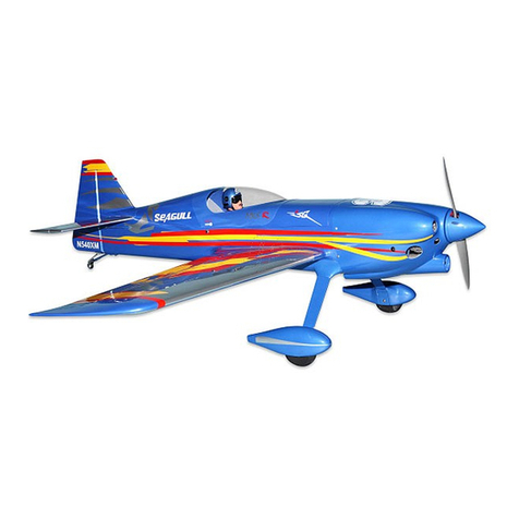
Der Jet Model F9F-8 Cougar User manual

Der Jet F9F-8 Cougar
Manual Version 3.0
Changes in version 3.0 include new strut door attachments, new parts pic-
tures and addendums on the nose strut, fuel system plumbing and speed
brake hinges.
Specifications:
• Length: 84 inches
• Wingspan: 70 inches
• Height: 29 inches
• Weight: 30-34 pounds
• Fuel Capacity: 5 Liters (170 ounces)
• Turbine: 24-36 pounds
Contents of Manual:
Introduction
• History of F9F-8 Cougar
• Kit Features
• Tools
• Glues
• General Preliminary Planning
Construction
• Page 6: Horizontal and Vertical Stabs
• Page 16: Air Systems
• Page 29: Fuel Systems
• Page 31: Split Flaps
• Page 33: Pipe and Engine
• Page 35: Wings
• Page 37: Receiver and Batteries
• Page 38: Cockpit
• Page 39: Nose Cone
• Page 39: Scale Details
• Page 41: Preparing for Flight
Appendices
• A: Suggested Equipment Layout
• B: Test Flying your Cougar
• C: Maintenance and Addendum's
• D: Parts Photos
Introduction
Der Jet F9F-8 Cougar Page 1

Thank you for purchasing the DerJet F9F-8 Cougar!
About your Cougar
The F9F-8 was the last fighter version of the Cougar to
see production. It was an attempt to reduce the stalling
speed, to improve the control at high angles of attack,
and to increase the range of the basic F9F-6. Known as
Design 99 by the company, work on the project began in
April of 1953. It featured an 8-inch extension of the center
fuselage. In order to reduce the stalling speed, Design 99
was fitted with extended and cambered leading edges in
place of the slats outboard of the fences. In addition, the
trailing edges of the wing were extended further aft. This
increased chord resulted in an increase of wing area from
300 to 337 square feet. It produced a wing with a rela-
tively thinner cross section which resulted in an improved
critical Mach number. Internal fuel was increased from
919 to 1063 gallons by adding a fuel tank in the extended
wing leading edge and by enlarging the forward fuselage
tank. The F9F-8 was fitted with a reinforced sliding can-
opy. The engine was the J48-P-8A or P-8C turbojet, rated
at 7250 lb.s.t. dry.
The first F9F-8 flew on January 18, 1954. A total of 601
F9F-8s were delivered to the Navy between April 1954
and March 1957. During the course of production, a fixed
inflight refuelling probe was added to the nose. Most F9F-
8s were fitted with a UHF homing antenna in a fairing un-
derneath the nose. Late production F9F-8s were fitted
with the capability of carrying two Sidewinder infrared-
homing air-to-air missile underneath each wing. This fea-
ture was retrofitted to many earlier F9F-8s. The first
Sidewinder-equipped Cougars were deployed overseas
by VA-48 in July of 1956.
On October 5, 1956, three VF-144 pilots set an unofficial
round trip record by flying their F9F-8s from NAS Mira-
mar, California to Long Island, New York and back with
refuelling stops each way at NAS Olathe, Kansas. The
total time was 10 hours 49 minutes 11 seconds.
The Blue Angels exchanged their F9F-5 Panthers for
F9F-8s in 1954. They flew the Cougars until they transi-
tioned to F11F-1 Tigers in the summer of 1957.
Several F9F-8s were converted into F9F-8B tactical nu-
clear bombers. They were fitted with the Low-Altitude
Bombing System (LABS), additional instruments, as well
as with the control and arming equipment needed for the
nuclear weapon, or "special store" as it was euphemisti-
cally called. However, in service most F9F-8Bs were op-
erated as conventional fighter-bombers and were pro-
vided with six underwing weapons pylons.
The F9F-8 and F9F-8B were withdrawn from fleet squad-
ron service in 1958 and 1959 respectively. They served
with reserve units until the mid-1960s, when they were
retired to the boneyards at Davis-Mothan
The Cougar was extremely popular with its crews, who
admired it for its ease of piloting, its superb carrier han-
dling capabilities, and its robust construction. However,
the F9F-8 Cougar was rapidly made obsolete by newer
supersonic designs that began to enter service in the late
1950s. The service life of the Cougar was consequently
Introduction
DerJet F9F-8 Cougar Page 2

relatively brief. The F9F-8 and F9F-8B were phased out
of active Navy squadron fleet service during 1958-59.
They continued to serve with Naval and Marine Corps re-
serve outfits until the mid-1960s. Some obsolescent F9F-
8s served for a time as drones and drone directors. Most
were retired to the boneyards at Davis-Monthan AFB in
Arizona. None were still in service by the time of the Viet-
nam War.
In 1962, the F9F-8 was redesignated F-9J under the new
Defense Department Tri-Service designation scheme.
The F9F-8B fighter-bomber became AF-9J. Later, when
used as advanced trainers, some of these aircraft be-
came TAF-9J.
Kit Features
• Live hinges on doors and split flaps
• Quality plywood with reinforced phenolic gear
mounts
• Pre molded light pockets on wings, with clear lens
covering, suitable for lighting kits
• Operating sliding canopy
• Operating tail hook
• Operating speed brakes
• Painted out of the mold, with a full complement of
detailed nomenclature
• Scale antenna and nose gear parts
• Twin carbon fiber spars
• 5 liter fuel capacity
• Large pipe, suitable for all engines
• Highly detailed, scale landing gear
• Disk brakes
• Inflatable rubber tires
• Removable nose cone
• High quality metal linkages
• Pre milled servo mounting plates and high quality
aluminum L brackets
• Molded main wheel wells
• Carbon fiber reinforced
Tools
While not mandatory, there is a short list of tools that will
speed the construction of your Der Jet kit. They include:
• Dremel tool equipped with a 1/16 cutter bit, rotary
grinder and cutoff wheel
• Latex gloves
• Wire size drills (available at Ace Hardware)
• Foam pads for protecting parts on the workbench
• Safety wire and pliers
• 4/40 and 6/32 taps
• Loctite
• JR matchmaker or equivalent
• Hand operated air pump
Glues
There are two primary glues you will utilize in the con-
struction of your Der Jet model.
• V-poxy and mixing nozzles: aircraft grade epoxy,
sets up in 3 hours and dries clear
• Medium CA and accelerator
Introduction
Der Jet F9F-8 Cougar Page 3

General Preliminary Work
•Inspect the aircraft thoroughly. Clean any
smudges or dirt as you go to keep it from setting
into the flat paint.
•Test all the air components with a hand pump to
check for leaks before construction. This should
include all landing gear, door cylinders, meters, fill
valves and any other optional equipment. It will be
easier to find leaks now than chasing problems af-
ter everything is installed.
•Paint the phenolic control horns to match your
paint scheme.
Early Decisions
Engine Choice
Empty weight of kit components is approximately 23
pounds, including the scale cockpit. Allowing for a typical
addition of 10 pounds for engine, accessories, servos and
batteries yields a finished weight of in the 32-34 pound
range. It is recommended that you utilize an engine in
the 30 pound class, though a lower thrust engine may be
acceptable if your aircraft weighs less or you are experi-
enced at flying aircraft at the lower end of the thrust to
weight curve. Donʼt forget to allow for the considerable
drag produced by the four flap surfaces and twin speed
brakes.
With a fuel capacity of 5 liters and an exit pipe diameter of
80 mm, the Cougar may handle slightly larger engines
while providing acceptable flight times, as long as top
speed is held in check.
Servo List
Generally, you should select the largest torque servo
available that will fit in the aircraft without modifying struc-
tural elements. Use metal geared servos, particularly on
the primary flight control surfaces and flaps. Do not in-
stall any less than 65 ounces of torque on each elevator,
or 155 ounces on the rudders. On these surfaces in par-
ticular, mount the servo arm clevis as close to the servo
spindle as possible while achieving the specified throw.
This creates added leverage and can reduce torque re-
quirements. The prototype aircraft made use of the fol-
lowing JR equipment:
•Elevators: JR 3421 (2)
•Rudder: JR 8411
•Ailerons: JR 8411 (2)
•Flaps: JR 8711 (2)(wing), 8611a (2)(split)
•Nose Steering: JR 2721 or JR 8411
•Air systems: JR 331, as required based on valve
selection
Air Systems
On the F9F Cougar, the main gear doors open, the gear
extend or retract and the doors close again. This is im-
portant, as there is not much clearance between the
ground and the doors when in the open position. The
nose gear doors, however, remain open with the gear ex-
tended. There are several choices for gear actuation:
Introduction
Der Jet F9F-8 Cougar Page 4

• UP2/UP4 combination, similar to F-15
• Electronic sequencers with dual door capability
• A single door sequencer, with a button switch for
the nose gear doors. In this configuration, the
main gear doors open and close via a sequencer,
while the nose door is tied into the servo air lines.
The line that connects to the cylinder to open the
doors is simply connected via “T” fitting to the gear
extend line. The door close line is similarly con-
nected to the gear retract line, with the addition of
a button switch that doesnʼt allow the cylinder to
pressurize until the gear is in the fully retracted po-
sition. This is the method illustrated in this manual.
Equipment Layout
This is a matter of personal preference. The aircraft illus-
trated here uses the following approach, fully illustrated in
Appendix B.
• Mainboard, supplied with kit: receiver, voltage
regulator and ECU. The fuel pump and solenoids
are mounted underneath the board.
• Fuel tank former, made up from scrap ply: Retract
and door valves, speed brake valve and tail hook
valve
• The brake valve may also be mounted to this
board, or Velcroed to the side of the fuselage adja-
cent to the fuel tank. This provides a short servo
run to the receiver.
• Length of servo extensions will be determined by
the final location of your receiver.
Channel Assignment
The following 12 channel assignment was used on this
model:
1. Throttle
2. Elevator (uses mixer)
3. Ailerons (uses mixer)
4. Rudder
5. Gear
6. Wing Flaps (uses mixer)
7. Split Flaps (uses mixer)
8. Wheel brakes
9. Nose gear steering
10.Speed brake
11.Tail Hook
12.Canopy
Construction Sequence
• Horizontal and vertical stabs
• Air systems
• Fuel systems
• Split flap system
• Pipe and engine
• Engine components
• Wings
• Receiver and electrical
• Cockpit, canopy and scale details
Note: the servo extensions are run as the construction
progresses.
Introduction
Der Jet F9F-8 Cougar Page 5

Construction
Horizontal and Vertical Stabilizers
Servo Installation
Remove servo hatches. It will be helpful to label them
as they are removed for side and orientation.
Using your Matchmaker or similar device, center the
servos and attach arms to match. Note orientation of
servos are with the spindles forward. (Note: in pic-
tures, a two hole arm is pictured. As construction was
completed, these were replaced with a four hole arm
to obtain sufficient throw.)
Using a scrap piece of ply approximately 3/16 x 1.25 x
1, create a backing plate for the JR 3421 servo. Do
not glue in place yet.
Use you Matchmaker to center servo to install arm
Above: Ply backing plate for servo
Left: Stab as it comes from the factory
Construction Manual
Der Jet F9F-8 Cougar Page 6

The JR 3421 sits down onto the ply mounts with the
servo case mounting tab fit into the machined slot in
the ply. The small triangular reinforcement tab will
contact the ply mount, setting the proper depth for the
servo.
Position the ply backer you made below the servo to
stabilize it. You may need to sand it slightly to allow
the servo to fully seat down on to the mounting plate.
When you are satisfied with the fit, remove the servo,
rough up the stab surface and CA the ply backer in
place.
Label the ends of your servo wires.
Midway between the two mounting bolt holes, cut a .5
inch diameter hole.
Run the servo wires to this hole and seat the servos
back into their mounts.
Add small blocks made from scrap wood fore and aft
of the servo to prevent lateral play.
Servo as first installed. Sand backer as needed to allow tab to sit down
fully on to mounting plate
Above: Small wooden blocks fore and aft capture servo.
Left: 1/16 inch cutter bit in Dremel tool routing servo wire hole
Construction Manual
Der Jet F9F-8 Cougar Page 7

Carefully mark the servo cover for the servo arm slot.
Double check you measurements twice, paying spe-
cial attention to the orientation marks you made earlier
on the hatch cover. Don't cut the slot all the way to
front. Start with the 1/16 cutter, check the position of
the slot, and if satisfied, widen slot to clevis width with
file.
With the cover in place, fill space between servo and
cover with tape until tight. The servo should now be
fully captured between the ply backer, the small scrap
blocks fore and aft, and the servo cover. Make sure
there is no slop or movement in the servo!
It is recommended that you use 3/8 inch button head
screws to insure the security of the cover. Donʼt over
torque the screws and deform the cover, however.
Mark lateral location of servo arm on plate. Reposition cover to the left to
mark for fore and aft measurements.
Slot rough cut. Check as you go to make sure the arm stays centered.
Use layers of tape to capture servo tightly against cover. It is now cap-
tured in all three axis by the ply backer, wood blocks and servo cover.
Construction Manual
Der Jet F9F-8 Cougar Page 8

Finished slot.
Linkages
Locate the 2” linkage rods.
Using a T square perpendicular to trailing edge, posi-
tion the rod and mark the elevator for the control horn
position. Donʼt forget to allow for offset of the ball link.
Position horn to the outside of the ball link.
Position the control horn with hole over hinge line and
mark the length of the slot, again using the T square to
keep the line perpendicular to the hinge line.
Use T-square to align linkage with hinge line and mark.
With clevis hole on hinge line, mark fore and aft extents of control arm.
Construction Manual
Der Jet F9F-8 Cougar Page 9

Tape around the marked line and carefully cut the con-
trol arm slot with the Dremel tool and 1/16 cutter, be-
ing very careful not to punch through the top of the
elevator surface. You should find a wood reinforce-
ment block in the elevator as you cut the slot. Make
sure the positioning of the horns is identical in both
elevators.
Drill the hole in the control horn with a #32 bit and
then rough up the gluing surface.
Using generous amounts of V-poxy, glue the control
horn in the slot. Make sure the horn is positioned ver-
tically with the hole over the hinge line. Make sure the
position of the arms in both elevators is identical.
Form nice fillets around the horns, carefully peel the
tape and set aside to dry.
Add pushrods. Their length should be approximately
3 inches. Secure position of clevis and ball link with
locking nut. Make sure the vertical position of the
servo arm is identical on both elevators.
Throw should be right at 30 mm, measured at the in-
ner end of the elevator.
Tape, inject glue and make nice fillet around each arm. Remove tape
before glue sets up.
Stab is now complete and ready for mounting.
Construction Manual
Der Jet F9F-8 Cougar Page 10

Rudders and Vertical Stab
Using V-poxy, glue four heavy duty hinges into the up-
per and lower rudders. The pivot point of the hinge
should be near the center of the radius of the leading
edge. This will likely be as far in as the hinge will go.
Make sure not to get any glue into the hinge itself.
Move the hinges to the side to make sure they are ori-
ented at 90 degrees to the rudder, and positioned at
the same depth.
Make sure hinges are perpendicular when installed.
Temporarily position top vertical stab into position on
fuselage.
Assemble top and bottom rudder to U bracket and
then trial fit the complete assembly to vertical stab.
Mark location of control arm on the U bracket so it is
centered in the middle of the access area.
Also mark the location of the steel hold down plates.
Disassemble the rudders and the U bracket.
Trial installation of rudders and U bracket. Note control arms are posi-
tioned approximately in the middle of the opening. You may need to
extend the flat spot on the U bracket to achieve this position.
Drill the holes for the steel hold-down plates with a
#37 drill and then refit the U bracket only and check
for free movement. It is extremely important that the
assembly move freely without binding, yet without any
fore and aft play. Slowly and carefully relieve the slot
if necessary. You should achieve a minimum throw of
30 mm measured at the bottom of the top rudder.
Secure the control horn to the steel U bracket with the
grub screw. Use Loctite. If you need to extend the flat
spot on the U bracket to properly position the control
arm, do so with a small file. (Note: if you are handy at
soldering, you may also solder the control horn to the
U bracket with aluminum solder paste or JB Weld.
Construction Manual
Der Jet F9F-8 Cougar Page 11

If you know your way around a soldering iron, you may choose to more
securely affix control horn to U bracket.
Current kits will have a servo mounting plate installed
in the lower vertical stab just below the horizontal stab
saddle. If this is the case, install your servo now with
the spindle forward.
Run your rudder servo extension.
Early kits were designed around a pull-pull cable sys-
tem to actuate the rudders. It is recommended that
you modify the horizontal stab as follows to position
the servo in the lower vertical stab.
As shown in the photo, cut two hardwood strips such
that they reach from the front vertical stab former to
the aft vertical stab former. You may need to trip away
a little at the aft portion to clear the vertical stab spar
clamp nuts.
Two hardwood strips approximately 15 mm square are installed between
the formers in the lower vertical stab just below the horizontal stab.
The depth of the two hardwood strips is determined by
running 2-25 linkage rods from the U bracket control
horn, through the holes formerly occupied by the cable
sheath in the aft former into the space where the
servo arm will be. Measure this distance from the
stab saddle.
To this figure, add the depth of the servo arm to the
bottom of the servo mounting tabs. Add in the depth
of the ply mounting plate to be cut out in the following
step. Mark this position on both sides of the fuse and
glue both hardwood strips in place. Measure several
times to make sure the depth is equal on both sides.
At this point, do not get any glue on the tops of the
hardwood strips, as the servo ply mounting plate
needs to sit down flush on the strips.
Construction Manual
Der Jet F9F-8 Cougar Page 12

Cut a servo mounting plate for the dimensions of your
servo. Length should be approximately 75 mm. Cut
the width to fit. It will taper slightly from fore to aft.
Glue the servo plate to the rails, centering the servo
hole with the access hole in the stab saddle. Use a
generous amount of V-poxy to secure the plate and
also reinforce the joints where the hardwood strips
meet the fore and aft formers.
Servo plate V-poxied to mounting rails. Note bead of glue along plate to
fuse joint.
This completes the modification required to earlier
kits.
Mount servo to mounting plate and connect to Match-
maker or receiver. Center servo and attach servo arm
with bolt.
Temporarily fit upper vertical stab to fuse.
Add rudders and recheck fit. When satisfied, inject a
generous amount of V-poxy into the hinge point holes
in the vertical fin structure. Refit rudders and U
bracket, reinstall steel straps and the servo arm, make
a final check for adequate movement from side to side
and set aside to dry.
Inject V-poxy into hinge holes and assemble upper vertical stab, rudders,
U bracket and steel straps and allow to dry.
Twin pushrods were fabricated from 2-56 rod with
threaded ends. Z bends are used to connect the rods
to the U bracket and clevises are threaded on to the
rods for attachment to servo arm. Carefully measure
length with components assembled as shown above
and then fabricate the pushrods.
Remove U bracket and attach pushrods. Reassem-
ble. Add clevises and attach to servo arm making
sure both sides are equal and the servo arm is cen-
tered. It is important to have the vertical stab installed
as shown as the tilt of the U bracket will affect the re-
quired length of the pushrods.
Construction Manual
Der Jet F9F-8 Cougar Page 13

Make sure to eliminate all play.
Be sure to install retaining clips as shown.
Rudder servo installed. Keep rods as close to the spindle as possible. Use
retaining clips.
Mount Horizontal Stabilizer
Run servo extensions to the front of the stab saddle
access hole. Connect servos using tape to secure.
Duct tape works well in this application. Make sure all
extensions clear the rudder servo and have adequate
clearance from exhaust pipe area.
Bolt the horizontal stab in place, using 35 mm bolts
and large washers. Use Loctite. Tighten securely, but
do not crush the stabilizer.
Double check to insure the stab sits down flat in its
saddle. You may need to relieve front of saddle
slightly to achieve a perfect fit.
Test elevator and rudder servos through the wiring
harness before proceeding to next step.
Stab bolted in place. Note slight grinding of front stab saddle to allow
stab to sit flat.
Permanently Mount Vertical Stabilizer
Check the hole in horizontal stab at rear to make sure
it is aligned with main spar clamp access hole. En-
large if necessary.
Measure the depth of the front vertical stab spar hole.
Make sure the 12 mm attachment bolt is long enough
to fully capture the threads in the front aluminum spar.
Thread the bolt into the spar, checking for a smooth fit.
(Note: on some early kits, the bolt may be too short.
You can make a trip to the hardware store for a longer
bolt or drill the front spar with a #36 drill and tap for a
Construction Manual
Der Jet F9F-8 Cougar Page 14

6/32 bolt, which you are likely to have in your spare
parts.)
Gently work vertical fin into place. It should be a snug
fit. Secure with 12 mm bolt and large washer, using
Loctite. You will be working blind, but if you feel for
the hole with your finger, the bolt should slip into
place. Do not force the bolt and risk stripping the
threads.
Snug the main vertical stab spar mounting clamp
through the access hole on the left side of the fuse-
lage. Use a 3/32 allen wrench. Do not strip out the
head of the bolt.
Final check of rudder assembly.
Notch tail cone to clear metal U bracket and install.
Notch tail cone to clear metal U bracket.
Attach tail cone with small wood screws, two per side. These screws
were left over from the horizontal stabilizer cover plates, which were
attached with heavy duty button screws as outlined in the instructions.
Construction Manual
Der Jet F9F-8 Cougar Page 15

Air Systems
Main Gear
Before you begin, test the retract units for smooth op-
eration and ability to hold air with your hand pump.
Inspect the retract pockets and grind the blind nuts
flush with the former if they protrude into the pocket.
Use a grinding or cutoff disk in the Dremel for this
task.
Blind nuts may protrude into pocket. If so, grind them down with your
Dremel tool or large file.
Unlock the trunnion pin in the retract unit so the gear
may be operated by hand. Position the unit into the
pocket, trimming material as necessary to achieve an
easy fit. Note that you will need to rout a small slot for
the air line that exits the side of the retract unit, and
clear an access holes for the aft retract mounting
bolts.
Note access holes for bolts, slot for side air line to clear gear mount.
The struts should be installed such that the scissors
face forward. The trunnion bolts that snug the struts
to the retracts should also be facing forward for easier
access.
The 4 mm retract mounting bolts may not fit properly
and if they are tight or don't align easily, don't force
them. You do not want to strip or displace the blind
nuts. Instead, slightly enlarge holes in the aluminum
gear mounting plate. Work carefully and take your
time to insure a good fit without creating excessive
play.
When you are satisfied with the installation, add air
lines and snug the bolts down. Check the operation of
the gear with your hand pump. If there is any binding,
Construction Manual
Der Jet F9F-8 Cougar Page 16

loosen the inner bolts only and operate the gear
again. If the problem has cleared itself, add shim
washers under the inner bolts and re-tighten. Repeat
if necessary until the gear is working properly.
Remove the bolts one at a time, Loctite and reinstall.
Nose Gear
Mount the steering servo to the steering servo frame.
Refer to photograph for proper positioning.
Nose gear unit with steering arms attached. JR 2721 servo is mounted
inverted from the bottom such that the servo and steering arms are level.
Make up linkage arms.
Center the servo using your Matchmaker, install servo
arm and linkages to the servo.
Add air lines to nose retract unit and check for proper
operation and leaks.
Mount gear to wooden nose frame with 4 mm x 15
mm bolts. Recheck operation of retract unit and shim
if there is any binding.
Install wooden frame to the nose of the aircraft, using
4 mm bolts of at least 25 mm in length. Make sure the
six bolts securely engage the blind nuts. Use Loctite.
Nose section mounted. This shows position of trunnion with gear in the
retracted position.
Recheck operation of nose gear and clear material
from the front of the nose gear door bay or forward
former if there isn't adequate clearance for the gear to
extend and lock.
Construction Manual
Der Jet F9F-8 Cougar Page 17

Retract in extended position. Small amount of material has been
cleared around the strut and trunnion block.
Door Brackets
Find four of the phenolic door brackets. Rough up the
gluing surfaces on these parts.
Examine the accompanying photos as you mark and
cut the slots for the door brackets.
Nose gear door: mark and cut a slot approx 80 mm
from rear of inner door lip for the air cylinder bracket.
The bracket should be positioned close to the door lip
adjacent to the hinge.
Main door: mark and cut a slot 20 mm from top door
lip at the forward edge of the door.
Tape around all four slots.
Apply a generous amount of V-poxy into each slot. A
glue nozzle really helps for this type of glue work.
Nose gear door bracket. Note orientation.
Location of main door bracket slot 20 mm down from lip. Tape prior to
gluing.
Construction Manual
Der Jet F9F-8 Cougar Page 18

Install the brackets, checking for proper orientation.
Form a nice fillet of glue and remove the tape. Check
one last time to make sure they are absolutely per-
pendicular to the door and set aside to dry.
When dry, touch up the fillets with white paint.
Door Cylinders
Cylinders are attached to the door brackets with the
10 mm screws and nuts provided, and may be at-
tached to the wooden L brackets provided with 15 mm
bolts and washers. Optionally, you may choose to drill
out the cylinder ends with a #43 bit and use #2 cap
head wood screws and nylon washers, which are
shown here.
Leak check a pair of 25 mm throw cylinders.
Attach both cylinders to the nose gear door brackets.
Tape nose gear doors shut.
Push the door cylinder ram until the valve is com-
pletely closed, then back off approximately 3-5 mm.
This will insure that there is pressure on the ram to
keep the door completely closed.
Mark the proper position for the wooden L bracket,
making sure the cylinder is vertical.
Glue the bracket in place with medium CA.
Repeat for opposite side
Clamp in place and allow the CA to dry completely.
Run a bead of V-poxy around the brackets to secure.
Wooden L brackets for nose cylinder mount
Main doors use the larger 40 mm throw cylinder.
Add air lines and check the cylinders for leaks and
smooth operation.
Attach unit to door bracket with 10 mm bolt and nut.
Fully retract the door ram and then extend it 3-5 mm,
as you did with the nose gear door cylinder.
Hold the cylinder parallel to the door and position the
wooden L bracket at the base of the door, in a similar
position to its orientation when the door is closed. You
will mark the wooden L bracket for distance from the
base. The hole should be positioned in the center of
the bracket vertically. See photos.
Attach the cylinder to the aft side of the wooden L
bracket, with the tab facing away from the cylinder.
Construction Manual
Der Jet F9F-8 Cougar Page 19

With the ram nearly retracted and against the door, position the wooden
L bracket (painted white in this photo) and mark for the bolt hole.
Completed installation. Note cylinder is attached to the back side of
wooden L bracket. Tab is positioned against front of wheel well.
Operate the gear by hand, fully extend the cylinder
ram and find the vertical position of the wooden L
bracket that gives the wheel adequate clearance. The
cylinder should be in line with the door bracket and the
wooden tab should be positioned up against the front
of the wheel well.
Mark its position, drill a several holes to give the glue
purchase and then rough up surface for better glue
adhesion. Glue the bracket in place with CA.
When the CA has cured, operate the door with your
hand pump. If necessary, adjust position of cylinder
attach bolt to get firm closure.
When satisfied, firmly secure wooden L bracket with a
generous amount of V-poxy.
Route a small hole in the forward part of the wheel
well and run air lines into fuse, securing top line with a
wire tie. Make sure there are no kinks.
Completed main door cylinder
Construction Manual
Der Jet F9F-8 Cougar Page 20
Table of contents
Other Der Jet Model Toy manuals

