Yeti SLOPE SOARER User manual

YETI SLOPE SOARER
WING 46"”
Thank you for purchasing the Yeti electric wing.
The Yeti electric wing is capable of stable flight, yet capable of aerobatics, its also tough and
rugged.
The Yeti can be flown from rough ground in challenging weather where others would be grounded.
Kit Contents:
> 100% EPP wing panels
> Laser cut Correx elevons & wing tips
> Full Hardware pack
> Picture Manual
Required to finish:
> Covering Pack + Glues
> 2 x Standard size servos , approx 43g
> RC transmitter capable of elevon mixing with at least 3 ch receiver
> 2600mah 4.8V Nimh battery pack (flat)
> Suitable charger for battery
Yetiwings encourages you to get insurance
at www.bmfa.org
COMBAT READY

Install carbon spar
Join wings
Bottom
Bottom
Join the wing halves accurately with
UHU por or hot glue, avoid epoxy.
Fill the pre-cut spar slot with UHU
por glue, insert the spar and tape in
place
Spar Slot

Overlay template as shown and draw
around shapes to be cut out
Cut out paper
template
Turn the wing over
You will need to cut out the servo,
battery and receiver apertures.
Its best to set the depth of the cut
using an adjustable knife so that you
do not cut too deep

3mm deep slot
A. Draw around your servos and cut to the correct depth, make “criss cross” patterns
and lever out the foam carefully with a screwdriver, checking for fit as you go.
B. Insert the servos, they should sit flush with the top of the wing, cut a shallow (3mm)
deep channel from the servo cable exit to the radio bay.
Also check that your chosen receiver fits with the servo plugs in.
Now remove all servos and receiver
A.
B.

Covering Stage 1 - Spray glue and Cross Weave Tape
TOP
Cross Weave
Strapping Tape
Repeat for the bottom of the wing DO NOT COVER THE WHOLE WING IN
STRAPPING TAPE. This will cause balance
problems later in the build
Give the top surface of the wing a generous coat of spray glue,
allow to dry for 5-10 mins
Apply the 50mm cross weave tape as shown, take care to wrap the
overlaps around to the bottom of the wing, trim where necessary.

Covering Stage 2 - Spray glue and Coloured Tape
TOP
Coloured tape
Turn the wing over, to show the top
Find a clean flat surface for the next stages
Give the wing another lighter coat of spray glue,and
allow to dry for 5-10 mins
Starting at the back edge of the wing, apply the
coloured tape, working forward in strips, overlapping by
approx 3mm or 1/8" inch, smooth each strip down as
you go.
Note, you will be judged by your friends on how many wrinkles you make :-)
Repeat for right hand wing, Then follow the
same procedure for the bottom of the
wing
If you wish to cover the elevons in coloured tape, do it now

TOP
TOP
3mm
2mm gap
2mm gap
You can make a hatches out of the
sheet of EPP foam supplied
Its time to put your servos back in. Find the holes you covered previously and
trim the tape away,
Seat the servos and use Cross weave tape to hold them in place, don’t forget to
put some coloured tape over to make it tidy.
Do the same for the servo cables, push them into the slot and re-cover
Pop the elevons out of the holder.
Cut some 50mm cross weave tape
down the middle to give you some
25mm lengths.
Run a strip of tape along the rear of
the wing, half on half off.
Attach the elevon, noting the 3mm
gap to the tip of the wing and the
2mm gap. Angle it down.
Turn the wing over and repeat, the
elevon should move quite freely up
and down

40mm
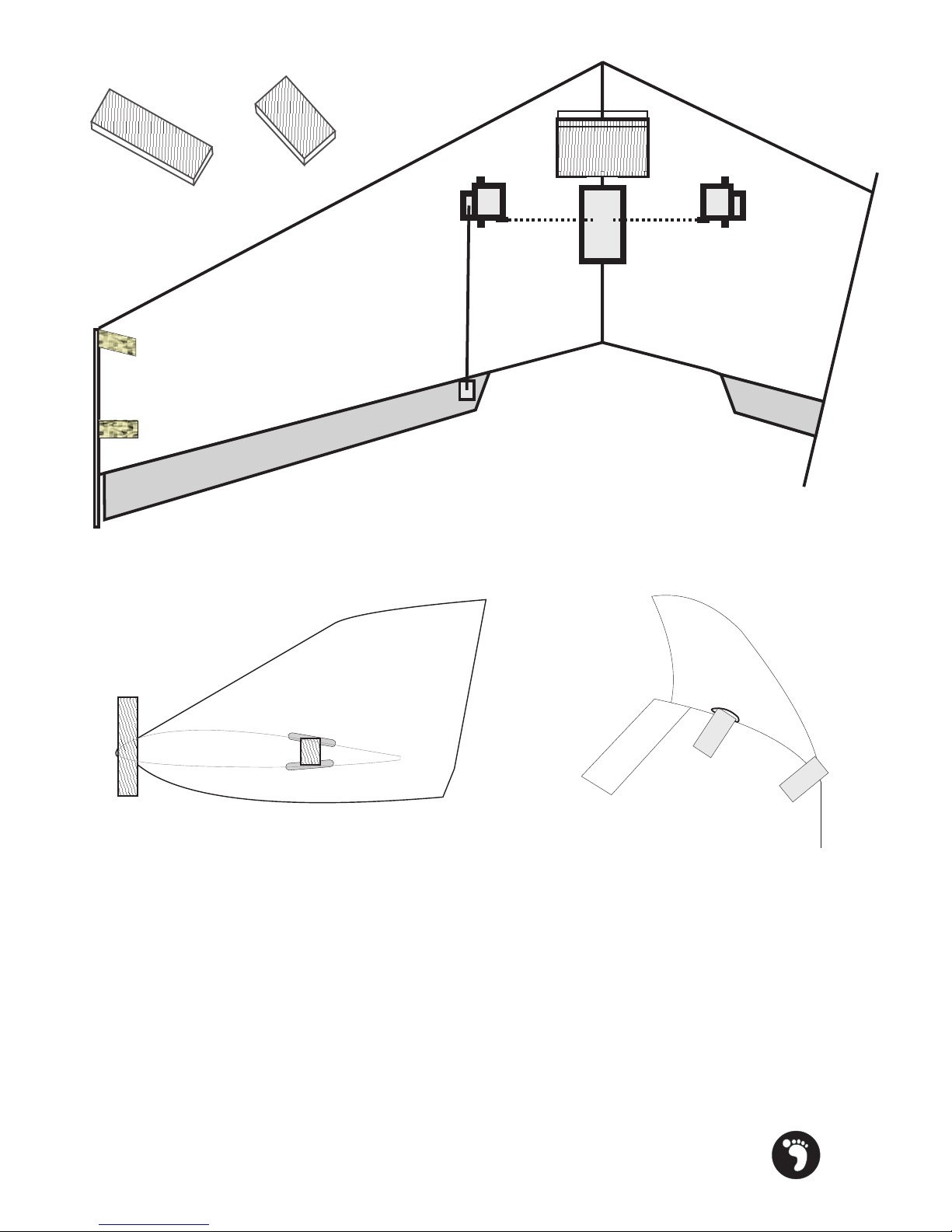
Use a ruler to mark the positions of the horn, put the screws into the horns
so that the point of the screws stick through by approx 1mm. Push the
horn onto the elevon in the correct place and screw down. Align the horn
bottom plate up with the screws and re-tighten, do not over tighten, just
enough to grip the elevon firmly.
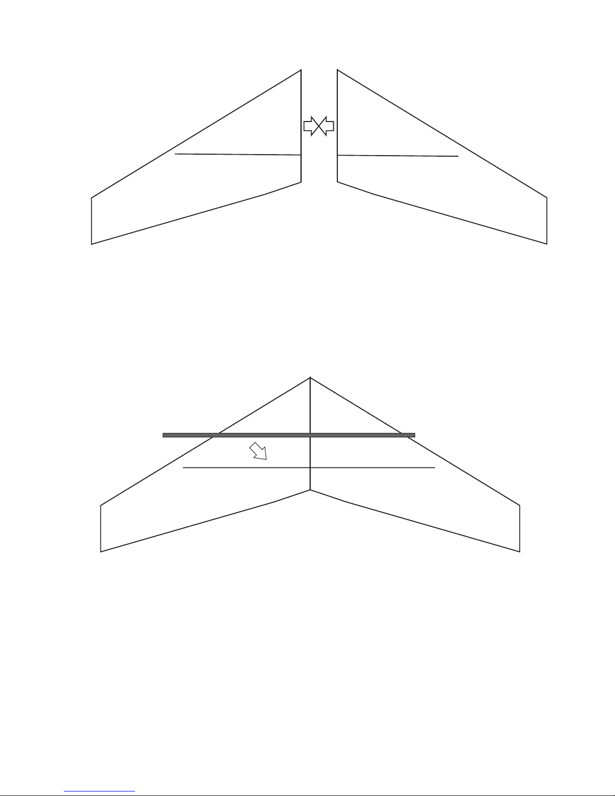
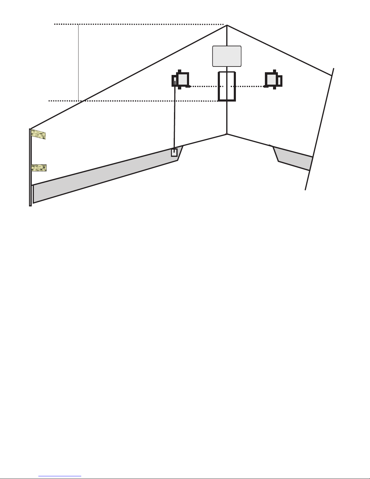
Switch on the radio system, neutralise all trims, check the horn is as
vertical as it will allow. Lay the model flat, the edge of the elevon should
be raised up 8mm from the surface. This is the neutral position.
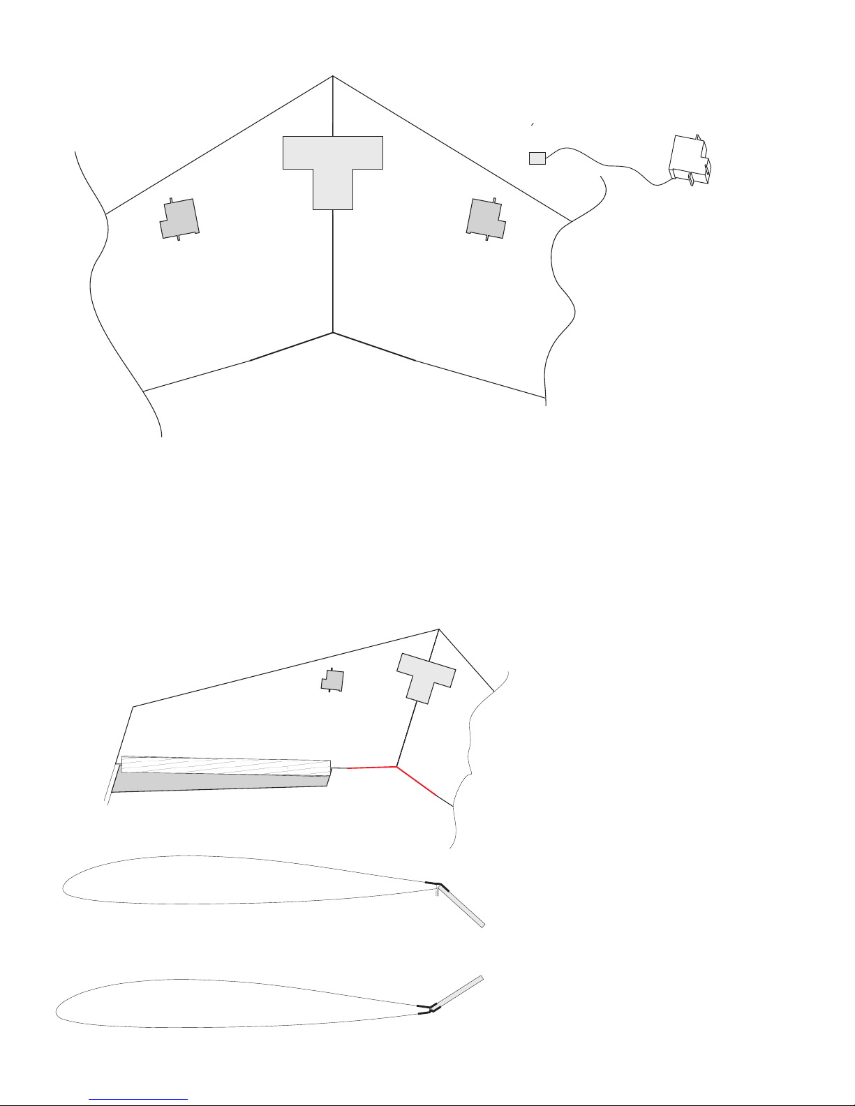
Create a z-bend with pliers. Take off clevis attach z-bend and re-attach
clevis, adjust accordingly.
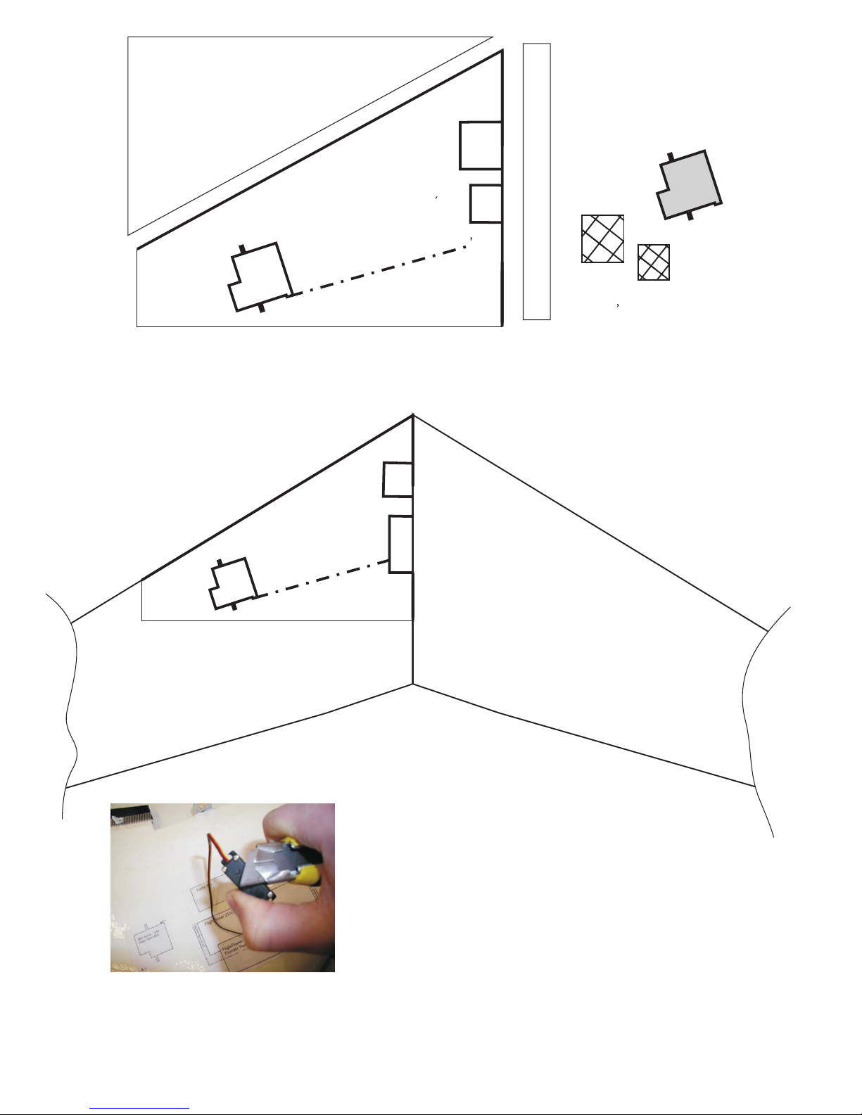
Installing the horns & pushrods.
SWITCH ON YOUR RADIO AND CANCEL ALL SUB TRIM
SET TRIMS TO NEUTRAL
Screw the screws into the horns so that the points of the
screws are just proud, Line up the horns as shown in FIG
5C, press down the horns, then screw them right down, get
the bottom part of the horn, align screws and screw down
until the horns grip the elevon, but not too tight.
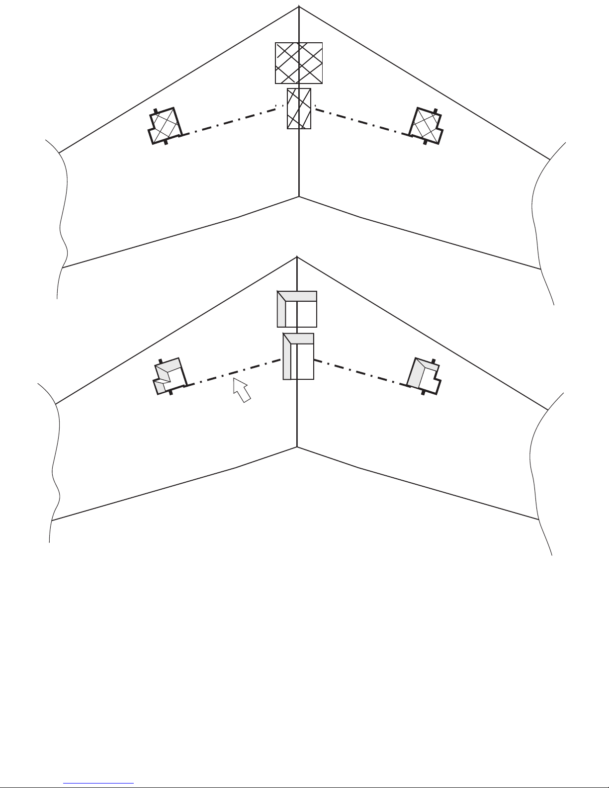
Screw the clevises onto the pushrods halfway, attach the
clevis to the servo horn, Set the elevon position slightly
upwards as shown, mark the pushrod with a felt tip and
make your z-bend at this point. Note the horn holes may
need to be enlarged slightly,
Use a ruler to set neutral position
Z-Bend

CENTRE OF GRAVITY 200MM

Attach Wingtips with filament tape, thread 5” of filament tape through the
pre-cut slots and tape to top and bottom of wing tip. Secure the front with
another piece.
Optional, Make some EPP hatches out of the sheet supplied, you can
hinge the battery bay with some strapping tape
Applying the vinyl graphics: Last job to be done
Step1: Carefully peel the white paper away from the backing paper (the
sticky paper that resembles masking tape) leaving the vinyl graphic on
the backing paper. If any part refuses to stick to the backing paper, press
it down between your fingers until it does.
Step2: Align the backing paper with vinyl onto the model where you wish
to apply it, rub it down firmly and peel back the backing paper to reveal
the graphic

Radio setup
Left stick should make the right elevon go down and the right
one to go up and vice versa
Back stick should make both elevon go up equally and vice
versa
View from rear of plane
Radio notes: Select “wing type” Delta or elevon on a computer radio, or use a v-tail mixer
unit.
trouble shooting
Everyone likes model aircraft to handle differently, but we list some
common problems
Q. The wing is very twitchy in roll (Aileron)
A. Reduce the travel limits down
Q. The wing is too sensitive in Pitch (up and down), check centre of
gravity, or add some more Exponential.
IMPORTANT
CENTRE OF GRAVITY
Measure back from the nose point 200mm, make a small mark.
With all the parts assembled and the battery in, the wing should balance
at this point. If the nose slightly tips forward that’s OK, If however the
wing tips back, place some lead into the nose, until balance is achieved,
failing to do this may render the aircraft unflyable.
Recommended control throws measured at trailing edge of elevon.
Up/Down +/- 20mm, Left/Right +/- 20mm, measure from the point shown by
the arrow >>
Important : When setting control throws, note that all 4 settings
(up,down,left,right) are the same whatever value. Ie all 75% or all 65%
We also suggest if available, to use Exponential on the elevons (Aileron &
Elevator) at 30%

This manual suits for next models
1
Table of contents
Popular Toy manuals by other brands

Laser Dollhouse Designs
Laser Dollhouse Designs Craftman One Car Garage Assembly instruction

Jamara
Jamara Veloce EP Instruction

MGA Entertainment
MGA Entertainment Little Tikes Fantastic Firsts 3-in-1 SwitchaRoo... quick start guide

Mattel
Mattel Disney PIXAR Cars 2 V6235 instructions

LEGO
LEGO Mixels Balk 41517 Building instructions

Fisher-Price
Fisher-Price GEOTRAX H8099 user manual