-7-
595-5631-07
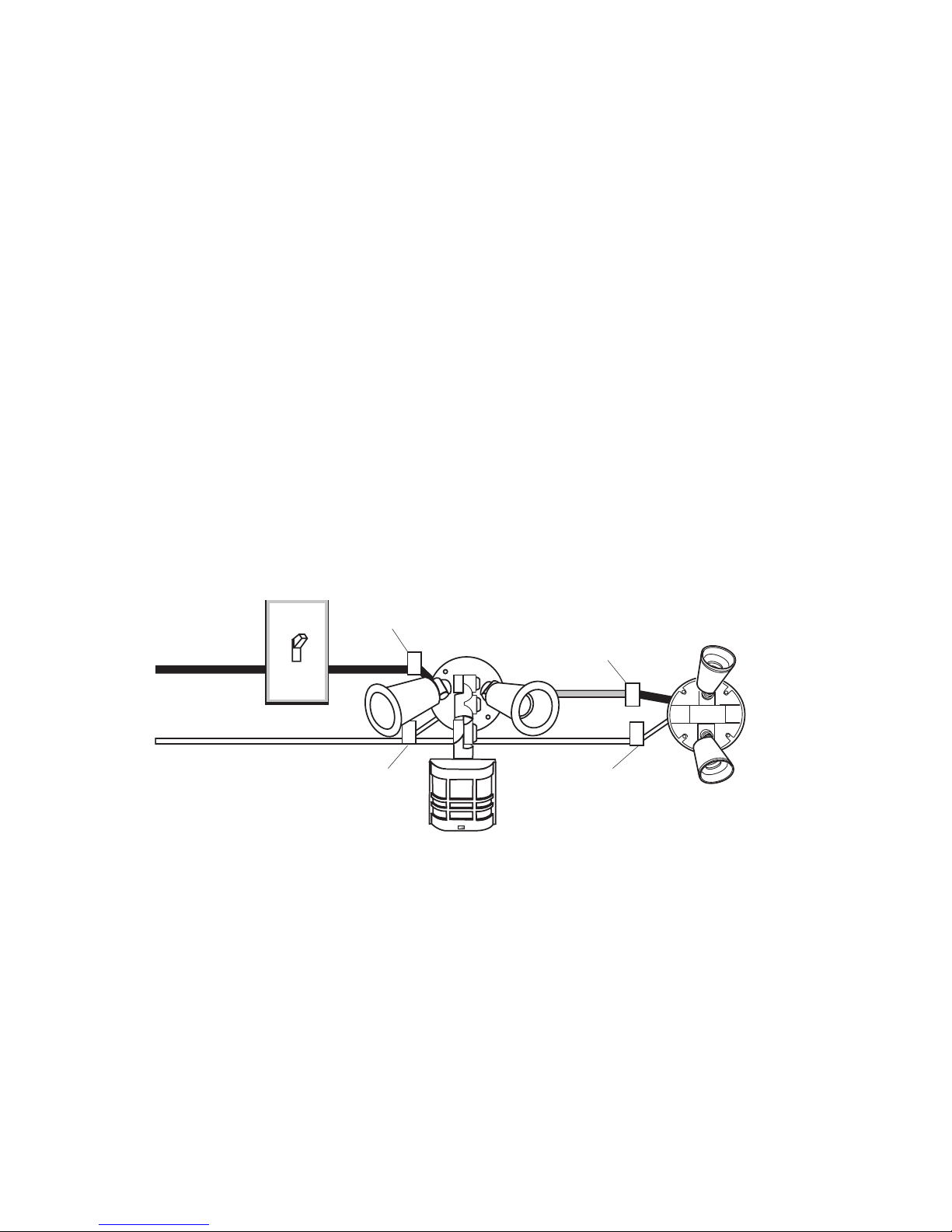
Controlling Non-Motion Sensing Fixtures
❒When wiring to additional standard fixture
only: Strip the motion sensor's red wire and
connect to the standard light's black wire. Con-
nect all white wires together. Total fixture
ratings must not exceed 1000W (8.3 A).
NOTE:All wiring between fixtures should be run
in accordance with the National Electrical Code
through conduit or another acceptable means.
Contact a qualified electrician if there is any
question as to the suitability of the system.
❒This fixture is provided with a sensor rated
for 1000W. Since the fixture is only rated 300W,
700W of additional load may be controlled by
this sensor.
❒When determining what a fixture is rated for,
do not simply look at the rating on the lamp in
the fixture. Look at the marking which speci-
fies the maximum lamp wattage for which the
fixture is suitable.
❒Once you have selected the fixtures to be con-
nected and determined their maximum ratings,
add these ratings up. For instance, if you have
3 fixtures rated 100W, 150W, and 75W respec-
tively, you have a total load of 325W.
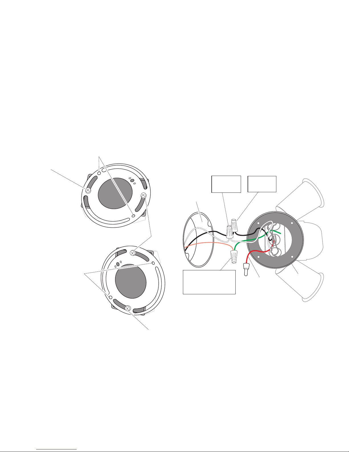
(Standard)
RED from
JourneyMan®
to BLACK
from Fixture
BLACK from
Switch to
BLACK from
JourneyMan®
WHITE from
Line to
WHITE from
JourneyMan®
WHITE from
Line to WHITE
from Fixture
Wiring to a Motion Light & Standard Fixture