TB-2039 Page 3 of 4
DESCO WEST - 3651 Walnut Avenue, Chino, CA 91710 • (909) 627-8178 • Fax (909) 627-7449
DESCO EAST - 90 Hudson Road, Canton, MA 02021-1407 • (781) 821-8370 • Fax (781) 575-0172 • Web Site: http://www.desco.com
Step 2: Connect the second test lead to the 675K jack
labeled “A” on the 07010. Touch the opposite end of
test lead to the test plate. Observe the LED’s for the
proper response as indicated below. Be sure to hold
the cord at an insulated point, so that the resistance
value is not affected by the body.
Resistance Value Test Output - LED
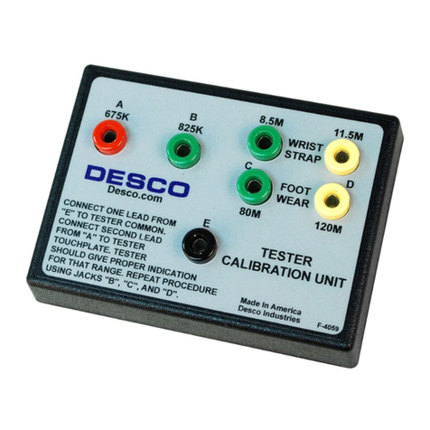
Red jack “A” - 675K: Red (Low - hazard)
Green jack “B” - 825K: Green (OK - in limits)
Green jack “C” - 8.5M: Green (OK - in limits)
Yellow jack “D” - 11.5M: Red (High resistance)
Step 3: Repeat the procedure testing across jacks B,
C, and D. The different resistance ranges should give
the display shown for the 19350. If the tester does not
meet calibration specifications, contact factory for
calibration, or ask for Technical Bulletin TB-2004.
Figure 7. Testing 19350 for “PASS” and “FAIL” ranges
as indicated on calibration unit.
CALIBRATION OF THE MODELS
19250, 19251 AND 19252
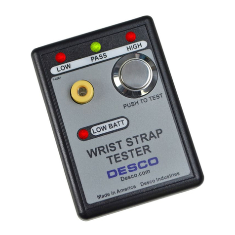
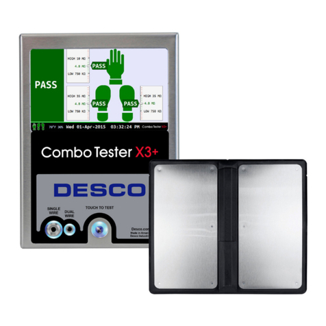
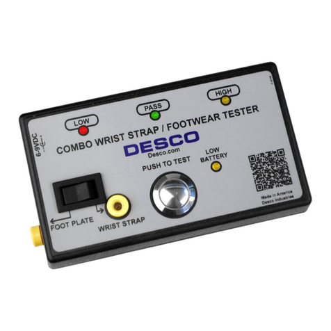
The models 19250, 19251 and 19252 testers utilize the
identical test unit. The difference between the three
models is the hardware that is included with each unit.
The model 19250 includes only the tester, model
19251 includes the tester and a metal foot plate, while
the 19252 is the tester and metal test stand assembly.
This test unit is designed with two separate test circuits
with distinct pass fail ranges. The wrist strap test
circuit incorporates a 750K - 10M pass range while the
footwear test circuit is set to pass at 750K - 100M.
Each test circuit needs to be tested individually. For
detailed information on these testers please ask for
Technical Bulletin TB-2040.
Wrist Strap Test Circuit
Step 1: Connect one of the test leads to common
point banana jack labeled “E” on 07010. Connect the
opposite end of test lead to the 19250’s wrist cord jack
located on the face of the unit.
Step 2: Connect the second test lead to the 675K jack
labeled “A” on 07010. Touch the opposite end of test
lead to tester’s test plate and press down with enough
pressure to activate the test circuit. Observe the LED’s
for the proper response as indicated below. Be sure to
hold the cord at an insulated point, so that the
resistance value is not affected by the body.
Resistance Value Test Output - LED
Red jack “A” - 675K: Red (Low - hazard)
Green jack “B” - 825K: Green (OK - in limits)
Green jack “C” - 8.5M: Green (OK - in limits)
Yellow jack “D” - 11.5M: Red (High resistance)
Step 3: Repeat the procedure testing across jacks B,
C, and D. The different resistance ranges should give
the display shown above. If the tester does not meet
calibration specifications, contact factory for calibration,
or ask for Technical Bulletin TB-2040.
Figure 8. Testing 19250 for “PASS” and “FAIL”, wrist
strap test circuit.
Footwear Test Circuit
Step 1: Connect one of the test leads to common
point banana jack labeled “E” on 07010. Connect the
opposite end of test lead to the 19250’s foot plate
ground jack located on the side of the unit.
Step 2: Connect the second test lead to the 675K jack
labeled “A” on the 07010. Touch the opposite end of
test lead to tester’s test plate and press down with
enough pressure to activate the test circuit. Observe
the LED’s for the proper response as indicated below.
Be sure to hold the cord at an insulated point, so that
the resistance value is not affected by the body.
© 2003 DESCO INDUSTRIES INC.
Employee Owned
