TB-3090 Page 4 of 8
Performing a Measurement
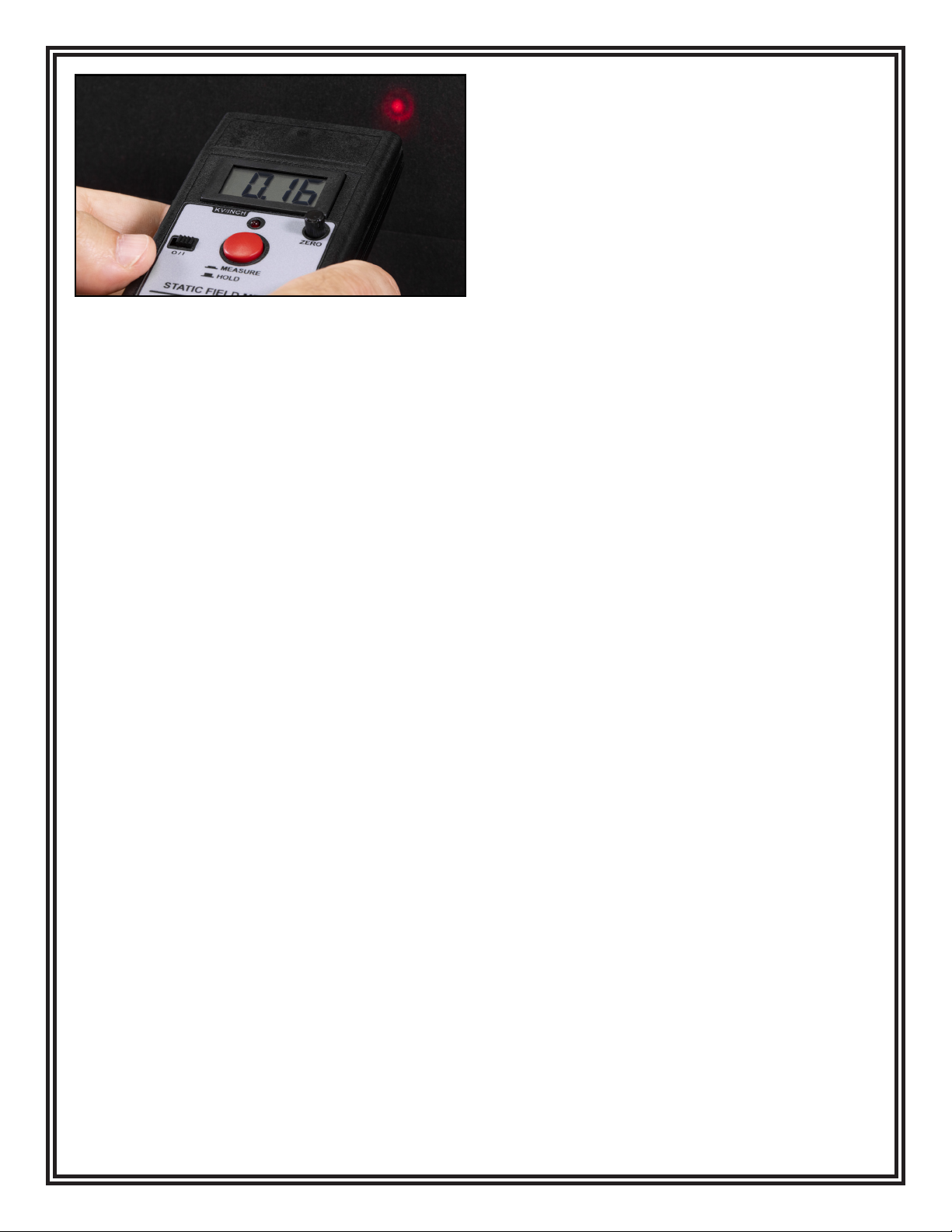
Use the LED range indicator to position the top of the
Digital Static Field Meter 1 inch (2.5 cm) from the object
to be measured. The Digital Static Field Meter will
display a reading (from 0 to ±19.99) of the electrostatic
eld in kilovolts per inch.
NOTE: The display will indicate “1” or “-1” when the
Digital Static Field Meter is over-ranged. Change the
range of the unit if necessary. If the measurement
exceeds 20 kV, move the Digital Static Field Meter
farther away from the object and multiply the reading
by the distance (in inches) away from the object being
measured. The measurement accuracy is dependent
on a stable ground reference and the 1 inch measuring
distance. It is also dependent on the “aspect ratio”,
relating the size of the object to be measured to the
measurement distance.
NOTE: This aspect ratio should be at least 3 for best
accuracy. In other words, the object should be at least
a 3 inch square when measuring at a 1 inch distance.
Accurate measurements may be made at other
measurement distances by scaling the Digital Static
Field Meter range and observing the proper aspect ratio.
For example, at a measurement distance of 3 inches,
multiply the Digital Static Field Meter reading by 3 to
give a range of 0 to 60 kilovolts. For accuracy, the object
being measured at this distance should be at least a 9
inch square.
Holding the Last Reading
With the Digital Static Field Meter positioned 1 inch
(2.5 cm) from the object being measured, press the
red pushbutton switch into the HOLD position. This will
freeze the measurement on the display and illuminate
the red LED located above the pushbutton switch. This
feature allows the operator to move the Digital Static
Field Meter where it may be more easily read or saved
for later reference.
NOTE: The LED range indicator will disable while the
Digital Static Field Meter is in HOLD mode. Use the
HOLD feature between measurements to prolong the
battery’s life.
Air Ionization Test Kit
Performing Oset Voltage (Balance) Measurements
The Air Ionization Test Kit has been designed to match
the
compact size and hand held convenience of the Digital
Static Field Meter. Use the following procedure to verify
the oset voltage (balance) of air ionization equipment.
This quick and easy procedure will help determine if
the piece of ionization equipment is working within the
manufacturer’s specications or user requirements. It is
extremely important that ionizers be checked regularly
for oset voltage (balance) and discharge times.
An ionizer operating in an out-of-balance state can
place a charge on sensitive electronic components or
assemblies.
NOTE: The Digital Static Field Meter’s enclosure is
conductive. The instrument senses the dierence in
potential between the enclosure and the tested surface.
The meter must be grounded by either the hand of a
grounded operator or the included coiled ground cord to
achieve accurate measurements.
Installing the Conductive Plate
The Digital Static Field Meter’s case has two slots
along its sides. The top slot is closest to the face of the
instrument. Slide down the tabs of the Conductive Plate
plate into the top slot of the Digital Static Field Meter’s
case as far as they go.
Figure 7. Aligning the two bullseyes emitted by the LED
range indicator
Test Equipment Depot - 800.517.8431 -5 Commonwealth Ave, Woburn, MA 01801 -TestEquipmentDepot.com