Cirris Touch1 LV Installation and operation manual

Touch1 Ultra
Performance Verification Manual
Version 2010.1.4
August 9, 2010
(ISO 9001 Certified)

Touch1 Ultra Performance Verification Manual
Version 2010.1.4
Copyright 2006 by Cirris Systems Corporation
All Rights Reserved
Cirris Systems Corporation
1991 W. Parkway Boulevard
Salt Lake City, Utah 84119
USA

Touch1 Ultra Checkout Manual – Page 1
Table of
Contents
Introduction..........................................................................................................................................2
Set Up ...................................................................................................................................................3
Tester Checkout Tests.....................................................................................................................4
Self Test
Touch Pad Test
Probe Test
Low and High Voltage Threshold Tests
High Voltage Tests
Capacitance and 4-Wire Tests
Scanner Tests
Tester Checkout Summary...........................................................................................................14
Appendix.............................................................................................................................................16
Calibration Certificate.....................................................................................................................18

Touch1 Ultra Checkout Manual – Page 2
Introduction
The Touch1 Ultra Performance Verification Kit allows you to verify calibration and proper
operation of the Touch1 Ultra tester. The Associated Research Hypot Ultra unit has it’s
own calibration procedure found in the Associated Research Hypot Ultra Users Manual.
Each Performance Verification Kit has a lifecycle of two years from the time of purchase.
At the end of two years, the kit can be recalibrated or replaced. All of the components for
this performance verification kit are tested with instruments traceable to the National
Institute of Standards and Technology (NIST).
Calibration should be performed on your Touch1 Ultra tester at least once a year. You
should also check the calibration whenever you suspect the tester may not be operating
properly. If the Touch1 Ultra tester fails any step in the performance verification
procedure, it must be sent back for repair. No external adjustments can be made to fix
the tester.
For information on setting up a calibration system to meet national calibration standards
such as ANSI/NCSL Z540-1, and ISO 10012-1, see the appendix of this manual.

Touch1 Ultra Checkout Manual – Page 3
Set Up
Packing List:
You should have received the following items with your Touch1 Ultra Performance
Verification Kit:
•This manual which includes a copy of a Touch1 Ultra Certificate of Calibration
•0.1% Resistor Leak Adapter
•T1/H+ Capacitance/4-Wire Adapter
•Zero Ohm Adapter
•HVI Block PCHK Adapter
Tester Preparation:
To prepare the tester for calibration, do the following:
•Install any expansion boxes you want to use. For information on how to do this, see
your Touch1 ULtra Users Manual.
•Connect the power cord to the tester. Plug the tester into a grounded power outlet.
•To print Tester Checkout results, connect a printer to the tester using the parallel port.
•Depending on your calibration system requirements, you may need to prepare a form
to record the results of the calibration. At the end of this manual is a Touch1 Ultra
Certificate of Calibration. If you use this form, make a photocopy so you can maintain
the master for the next time you perform the calibration tests.
•Special equipment is required to do the high voltage tests. To do the high voltage
tests, be certain your voltmeter is equipped with a high voltage probe. For
testing above 1000 volts DC, your voltmeter must be equipped with a high voltage
probe which has > 50M ohms of input resistance and be able to safely withstand over
1500 volts DC. Your voltmeter may be damaged if you do not take these
precautions.

Touch1 Ultra Checkout Manual – Page 4
Tester
Checkout
Tests
1. From the Main Menu, press System Setup.
2. At the System Setup screen, press Tester Checkout.
3. The Tester Checkout Selection screen allows you to decide which tests you want to
run for your calibration process. You can select Full Calibration to run all of the tests
or you can select an individual test to run.
Touch here for
full calibration
General Procedures for all Tests
•To switch a test option on, touch the button for that test so a checkmark appears inside
of the box. If there is no checkmark inside the button, the test is turned off.
•To start a test, press Next Test X where X lists the test to be performed. The Touch1
Ultra will perform the test and then show either a Pass or Fail result. You can abort any
test except the Touch Screen Test by pressing the Abort button. The Touch Screen Test
will automatically abort if the screen is not touched for ten seconds.
•To proceed to the next test you have selected, press Next Test X. If all the tests have
finished, press Show Summary.
•If during testing you want to cancel all remaining tests and see a summary of the test
results so far, press Cancel.
•To print the results on a printer, press Print. Some tests have individual summary results
you can also print.

Touch1 Ultra Checkout Manual – Page 5
Self Test
When this test is selected, the Touch1 Ultra will perform ten passes of a series of major
tests. These are the same tests performed automatically on power up. They test the basic
functionality of the tester to see if it can perform reasonable measurements within
specification. Some of the tests include the voltage measurement gain circuitry, the high
voltage circuitry, the high-current source, the negative current clamp, the capacitance
measurement hardware, etc.
1. To start the test, press Next Test: Self-Test.
2. All ten passes must complete without errors for the tester to pass Self Test.
This screen shows the
seventh pass for the group
of self tests being done.

Touch1 Ultra Checkout Manual – Page 6
Touch Pad Test
The Touch Pad Test tests the touch screen to be sure is it working properly.
1. To start the test, press Next Test: Touchpad.
2. A screen with a calibration button in the upper lefthand corner will be displayed.
Press the center of the picture inside the button.
Touch the center of
the button to
calibrate.
3. A screen with a calibration button in the lower righthand corner will be displayed.
Press the center of the picture inside the button.
4. A screen with five buttons will be displayed. Press each button to check the
calibration. You must press a button within ten seconds or the test will fail. A star
should appear where the screen was touched. If the star is not drawn where the
screen was touched, the calibration is not correct. Let the test fail by waiting ten
seconds without touching the screen and perform the Touch Pad test again to
correctly calibrate the touchscreen.
5. To pass the test, all five buttons must be pressed before the timeout.
To check the
calibration, press all
five buttons making
sure a star is drawn
where the screen is
touched.

Touch1 Ultra Checkout Manual – Page 7
Probe Test
The Probe Test tests the ability to correctly identify probed test points. Any one of the
adapters included in the Performance Verification Kit are needed to perform this test.
1. To start the test, press Next Test: Probe.
2. A screen will prompt you to install any adapter in the J1 position on the scanner.
Install the Resistance adapter into the HVI Block Adapter.
3. Install the HVI Block Adapter into the far left hand position (Pin 1) on the scanner
assembly. Once the HVI Block Adapter is in place, press OK.
4. Touch the tip of the probe to the HV test point(s) on the adapter. If the probe is
working correctly, a pop-up window will display the correct point(s) touched by
the probe. If no pop-up window is displayed when the test point(s) are probed,
press No Response. The test will fail and a Failed Probe Test screen will display.
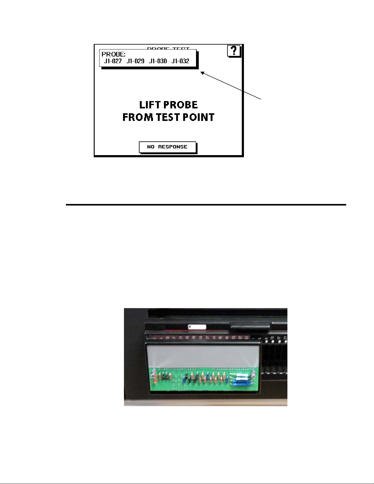
Touch1 Ultra Checkout Manual – Page 8
To display the pop-up
probe window, touch
the probe to any test
point(s) on the
adapter.
5. Release the probe from the test point(s) and a Passed Probe Test screen
will be displayed. If the screen does not change when the probe is
released from the test point(s), press No Response. The test will fail and a
Failed Probe Test screen will be displayed.
LV + HV Meas. (R) Test
The LV/HV Measurement Test checks the low voltage and high voltage measurements. To
pass the test, the Touch1 Ultra must measure the resistor’s value to +- 1% +-0.1 ohm and
the high voltage leakage at 5M ohm +- 10%. The Resistance Adapter included in the
Performance Verification Kit is needed to perform this test.
1. To start the test, press Next Test: LV/HV Meas.
2. A screen will prompt you to install the Resistance Adapter in the J1 position on the
scanner. Install the Resistor Adapter into the HVI Block Adapter. Install the HVI
Block Adapter into the Pin 1 position as shown and then press OK.

Touch1 Ultra Checkout Manual – Page 9
3. The Touch1 Ultra will perform the tests and display either a Pass or Fail result for
each test.
Scroll down to view
the results for all the
tests.
HV Voltages (R + V) Test
The High Voltage Test checks that all the voltages in the high voltage settings of the
Touch1 Ultra are within range. The Associated Research Hypot Ultra voltages are calibrated
separately using the Hypot Ultra Users Manual.
To pass this test, all the voltages must be within 10% of the high voltage setting. The
Resistance Adapter included in the Performance Verification Kit is needed to perform this
test. You will also need a voltmeter with a high voltage probe.
In general, the high voltages on the Touch1 Ultra tester are not considered dangerous
because the current is limited to a safe level. However, touching cable connections when
high voltage is applied causes an unpleasant shock. An operator who has a health condition
that could be aggravated by a startle should not do high voltage tests.
Special Equipment is required:
To do the high voltage tests, be certain your voltmeter is equipped with a high voltage
probe. This is beyond the range for most ordinary voltmeters. For testing above 1000
volts DC, your voltmeter must be equipped with a high voltage probe which must have >
50M ohms of input resistance and be able to safely withstand over 1500 volts DC. Your
voltmeter may be damaged if you do not take these precautions.

Touch1 Ultra Checkout Manual – Page 10
1. To start the test, press Next Test: HV Volts
2. A screen will prompt you to install the Resistance Adapter in the J1 position on the
scanner.
A high voltage probe
is required to perform
the HV Volts test.
3. Install the Resistance adapter into the HVI Block Adapter. Install the HVI Block
Adpater into the Pin 1 position and connect your high voltage probe to the HV test
pins on the adapter as shown. Then press OK.
Attach the high
voltage probe to the
test pins shown here.
4. The Touch1 will apply high voltage during each test so keep your hands clear from
all connections during the test. Press START to begin the test.
Press START to begin
the series of high
voltage tests.
Touch1 Ultra Checkout Manual – Page 11
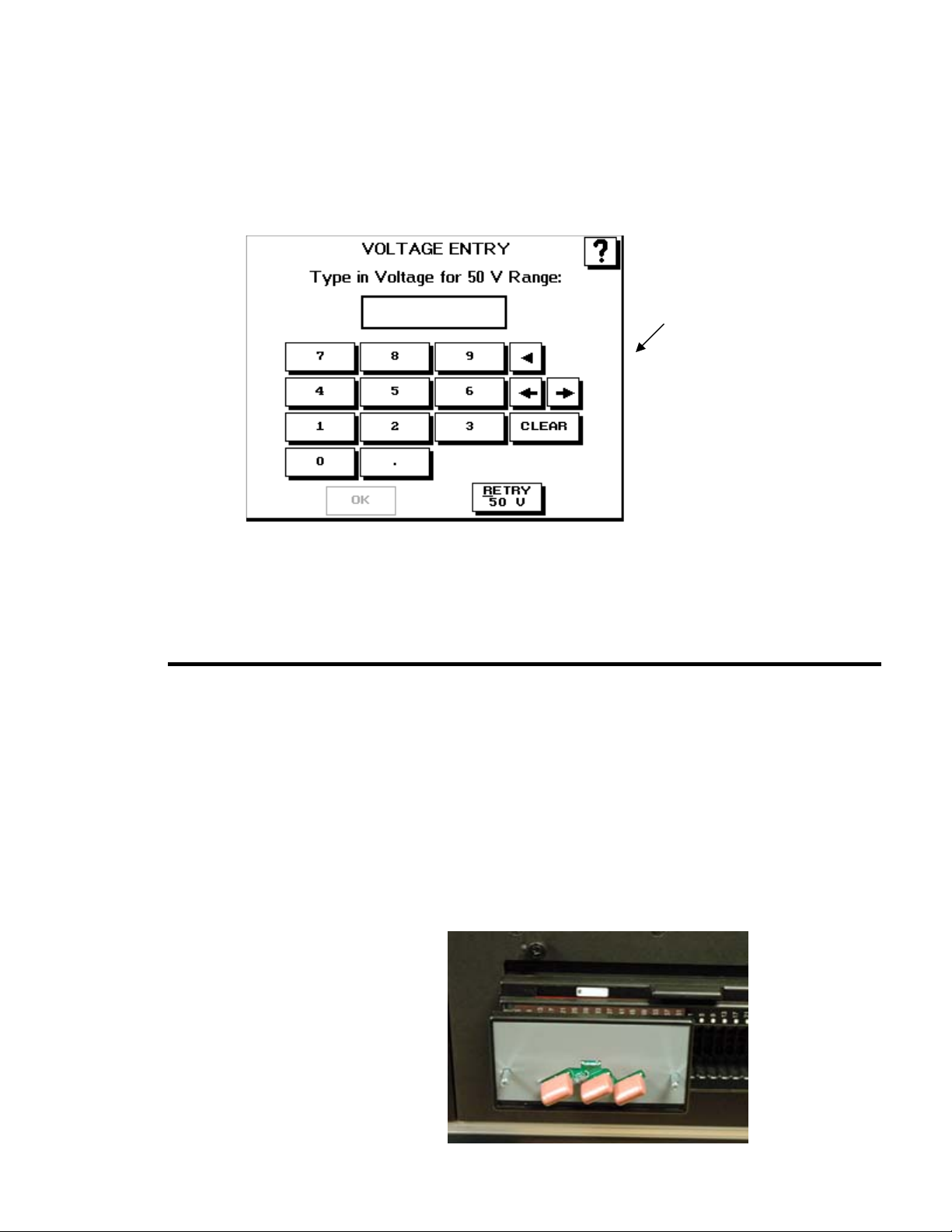
5. Read the voltage from your voltmeter and press RECORD VOLTAGE to enter the
reading from the voltmeter. Press OK to continue on to the next voltage or press
RETRY x V where xis the voltage the test will retry. Note: The HV Test will timeout if
the Record Voltage button is not pressed.
Enter the voltage
displayed on the
voltmeter here.
6. Repeat steps 4 and 5 until all the voltages have been tested and recorded. After 50
volts, the tests will increment by 100 volts until 1500V. The Touch1 Ultra will perform
the tests and display an overall summary with either a Pass or Fail result for each
test. If any of the the voltages do not pass, the entire HV Test will fail.
Capacitance/4-Wire (C) Test
The Capacitance and 4-Wire Test checks the Touch1 Ultra can accurately measure
capacitance and perform a 4-Wire test. To pass the test, the Touch1 Ultra must measure
the capacitor’s value to ±10% and the 4-Wire resistor to ±1% ±0.001 ohm. The
Capacitance/4-Wire Adapter included in the Performance Verification Kit is needed to
perform this test.
1. To start the test, press Next Test: Cap. & 4W
2. A screen will prompt you to install the Capacitance/4-Wire Adapter in the J1
position on the scanner. Install the Capacitance/4-Wire Adapter into the HVI
Block Adapter. Install the HVI Block Adapter into the Pin 1 position as shown
and then press OK.

Touch1 Ultra Checkout Manual – Page 12
3. The Touch1 Ultra will perform the tests and display either a Pass or Fail
result for each test.
Results will be
displayed for both the
capacitance and
fourwire tests.
Scanner Test
The Scanner Test verifies the analog circuitry and relays inside the scanners are working
properly all the way to each test point. The test checks for loose scanners making sure the
cables are connected properly. Run this test to isolate capacitor measurement errors, high
resistance shorts, and leakage errors by eliminating or identifying contamination on
scanners as the cause of the problem. The Zero Ohm Adapter included in the Performance
Verification Kit is needed to perform this test.
1. To start the test, press Next Test: Scanners
2. A screen will prompt you to install the Zero Ohm Adapter in the J1 position
on the scanner. Install the Zero Ohm Adapter into the HVI Block Adapter
Install the HVI Block Adapter into the Pin 1 position as shown and then press
OK.

Touch1 Ultra Checkout Manual – Page 13
3. The Touch1 Ultra will perform the test and display either a Pass or Fail result
for each portion of the test. A screen will then prompt you to remove the
adapter and install it in the next “J” position on the scanner. Two tests are
done for each scanner. One for each double-high position.
4. The test automatically sequences to the next step if it can detect the removal
of the adapter. If it cannot detect the adapter was removed, you must press
the NO RESPONSE button.
Remove the adapter
to automatically
proceed to the next
test.
5. Remove the HVI Block Adapter and place it into the next Pin 1 position as
shown.
6. If the tester has any expansion boxes installed, continue testing the other
scanners by moving the HVI Block Adapter to each of the “Pin 1” positions
and running the test.

Touch1 Ultra Checkout Manual – Page 14
7. At the end of all the tests, a scanner summary screen will be displayed listing
the results for each test section. If any of the the individual scanner tests do
not pass, the entire ScannerTest will fail.
Results for six
separate tests will be
displayed for each
scanner attached.
Tester
Checkout
Summary
1. To see the TESTER CHECKOUT SUMMARY screen for all the Tester Checkout Tests,
press Show Summary. Use the arrow or scroll buttons to view all the results.
•The summary will display ABORTED for any aborted tests.
•The summary will display SKIPPED for any skipped tests.
•The summary will display FAILED for any failed tests.
2. To save the Test Summary results, you must either print them or copy them to paper
by hand. If you have a printer connected to your Touch1 Ultra, you can print the Test
Summary by pressing PRINT.
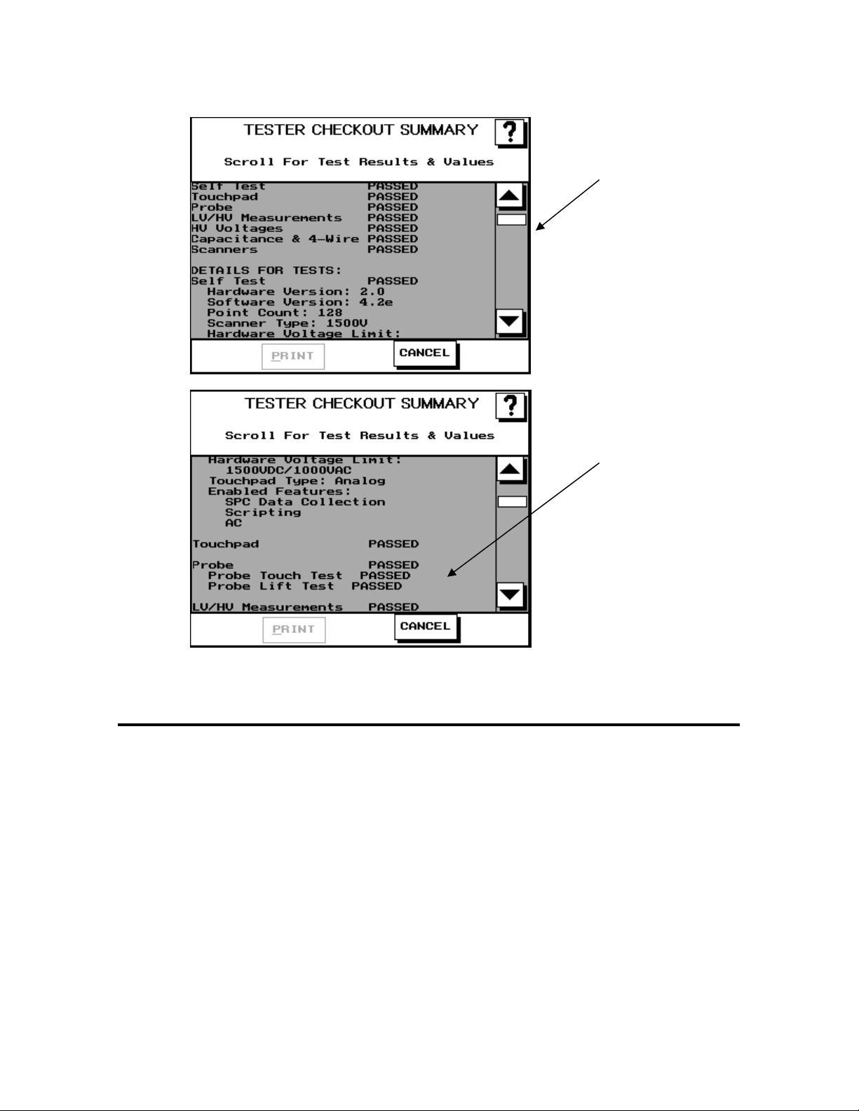
Touch1 Ultra Checkout Manual – Page 15
An overall summary
is given for each test
along with the
individual test results.
Scroll down to view
the individual results
for all the tests.

Touch1 Ultra Checkout Manual – Page 16
Appendix
The following information can be used a guide for setting up a formal calibration system in
your organization.
Calibration Standards
Calibration standards refer to written quality system requirements for organizations that
perform calibations and use calibrated equipment. Establishing a quality system according
to calibration standards helps insure calibrations are done competently and lends credibility
to the calibration organization. In the United States, common calibration standards include
ANSI/NCSL Z540-1, ISO/IEC Guide 25, ISO 10012-1, and the former MIL-STD 45662A.
The ANSI/NCSL Z540 standard refered to above, as well as other helpful metrology
information, can be obtained from the National Conference of Standards Laboratories
International (NCSL) at 1-303-440-3339 or www.ncslinternational.org. You can obtain the
ISO standards from the International Standards Organization (ISO) at their web site
www.iso.net/.
The word “standards” is often used in another way in the metrology industry to refer to a
centralized, most accurate unit of measurement regulated by countries. The National
Institute of Standards and Technology (NIST) maintains the national standards for
measurements in the United States.
Good Calibration Practices
The calibration standards, such as ANSI/NCSL Z540-1 and ISO 10012-1, require several
good practices for the calibration industry including the following areas:
Recall System
How do you ensure your company does not forget to send an instrument in for
calibration? Use a recall system which can be a card file or a computerized database,
This system includes calibration dates, due dates, calibration sources, and other
instrument records. The recall system ensures calibrated instruments are recalibrated
in a timely manner.
Calibration Labels
How does someone know if an instrument has been calibrated without looking for the
paperwork in a filing cabinet drawer? When an instrument is calibrated, the calibration
standards require the instrument to be labeled as such. The calibration labels, which
are applied to instruments, have fields for the instrument serial number, calibration
date, calibration due date, and by whom. A good source of inexpensive calibration
labels is United Ad Label at 1-800-992-5755.
Accuracy Ratios
Can you use a ruler to calibrate your digital calipers? Of course not! Wherever
possible calibration standards require an accuracy ratio of at least four to one. In
other words, the insturment being used to measure the calibrated instrument must be
at least four times as accurate as the calibrated instrument.

Touch1 Ultra Checkout Manual – Page 17
Certificate of Calibration
How does everyone know you had an instrument calibrated?The calibration
certificate is the record of who, when, and by what equipment the instrument was
calibrated. A Touch1 Ultra Certificate of Calibration, which you can photocopy for your
calibration, is provided following this section.
Calibration Data Report
So just how accurate is the calibrated test instrument in relation to its published
specifications? Some organizations require the measured values of a calibrated
instrument are written down when an instrument is calibrated. Calibration laboratories
typically charge extra to create a calibration data report. However, when a calibrated
instrument is found to be out-of-tolerance, the calibration standards require the out-of-
tolerance data be recorded in relation to the instruments specifications. A calibration
data report can fill this requirement. The Tester Checkout Summary from the Touch1
Ultra tester can be used as a calibration data report. This report can be printed or
copied to paper by hand.
Traceability
Did qualified personnel perform the calibration procedure under controlled conditions,
using correctly calibrated instruments with the correct test accuracy ratios? To
maintain traceability, the answer to all these questions must be yes. Traceability
refers to each unbroken link of valid calibrations going back to national standards
such as those maintained by the NIST in the United States.
Several years ago NIST numbers (ie. reference numbers issued on NIST reports)
were commonly copied on successive calibration certificates as a means of showing
traceability. This practice has been discontinued. Therefore, if you are writing a
calibration procedure, do not require NIST numbers be copied on reports to show
traceability. NIST numbers are sometimes confused with other numbers that
calibration laboratories create for reference such as “asset numbers”, “NIST trace
numbers”, “ID numbers”, and report numbers. For more information regarding the
discontinued use of NIST numbers, contact Cirris for a copy of the position paper
from the National Conference of Standards Laboratories.

Touch1 Ultra Checkout Manual – Page 18
Touch1 Ultra Certificate of Calibration
Name and Address of Organization Performing the Calibration:
Certificate Number: Calibrated by:
Calibration Date: Due Date:
Applicable Calibration Standard(s): Procedure:
Touch1 Ultra PCHK Version 1.3
Temperature: Relative Humidity:
Tester Serial Number:
Instruments used: Serial Number Cal. Date Due Date
Zero Ohm Adapter
Resistor Leak Adapter
Capacitance/Fourwire Adapter
HV Block PCHK Adapter
Voltmeter
Statement of Traceablility:
Certified by:
Other manuals for Touch1 LV
1
Table of contents
Other Cirris Test Equipment manuals

Cirris
Cirris CH2 User manual

Cirris
Cirris CH2 User manual

Cirris
Cirris Easy-Touch Pro User manual

Cirris
Cirris Touch 1 User manual

Cirris
Cirris Easy-Touch Pro User manual

Cirris
Cirris CH2 User manual

Cirris
Cirris signature 1100R+ User manual

Cirris
Cirris CR User manual

Cirris
Cirris CH2 User manual

Cirris
Cirris CH+ User manual

Cirris
Cirris CH2 User manual

Cirris
Cirris 4200 Series User manual

Cirris
Cirris CH2 User manual

Cirris
Cirris 4200 Series User manual

Cirris
Cirris CR User manual

Cirris
Cirris CR User manual

Cirris
Cirris CH2 User manual

Cirris
Cirris easy-wire CR User manual

Cirris
Cirris Touch1 LV Installation and operation manual

Cirris
Cirris 4200 Series User manual


