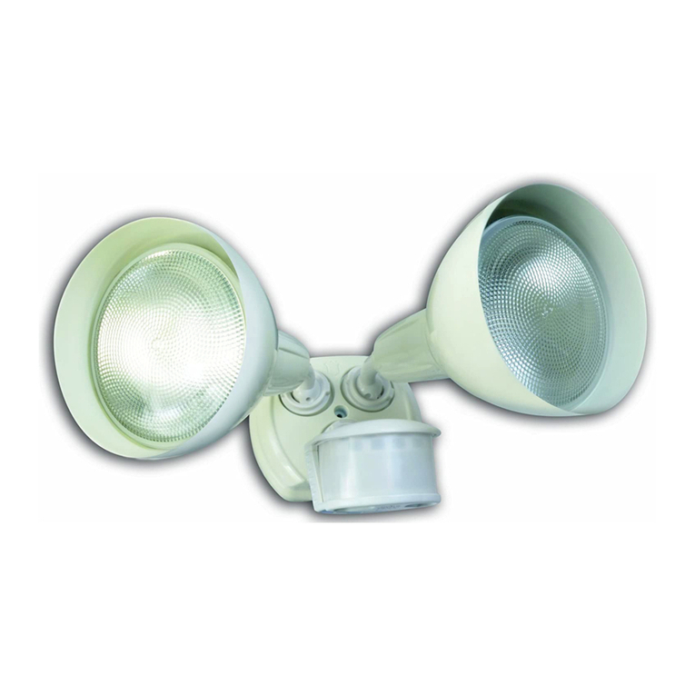
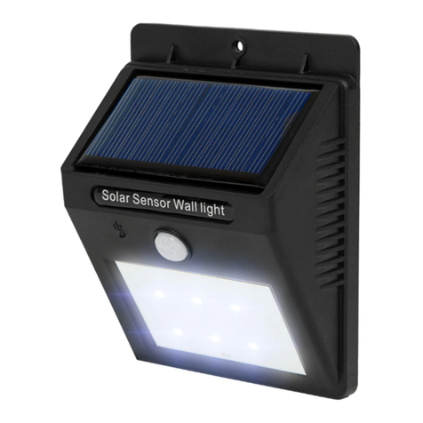
Designers Edge L5999 User manual

INFARED MOTION ACTIVATED
SECURITY LIGHT INSTALLTION
INSTURCTIONS
Model # L5999
10 Year Warranty on Fixture
(Does not apply to bulbs, which have no warranty)
Congratulations and Thank You! The fixture you have purchased should give you 10 years of
trouble free service. We take pride in the design and construction of each of our products
and work to maintain the quality of our materials and craftsmanship to assure your
satisfaction.
This product is warranted to be free of defects in workmanship and materials for a period of
10 years from the original date of purchase. If any problems appear (other than burnt out
bulbs, which carry no warranty) within 10 years, the purchaser may return the item, freight
prepaid, together with a copy of your original purchase receipt to:

Southwire Co. 11290 80th Ave. Pleasant Prairie, WI 53158
Upon receipt of the item prepaid with a letter describing the problem, and a check for $7.50
to cover return postage and handling, the company will, at its option, either repair or replace
the defective part or fixture at no charge to the purchaser. This warranty does not apply to
fixtures that have been used for rental or commercial purposes. It does not cover fixtures
that have been altered in any way or fixtures that have been subject to misuse, accidents or
damage in transit.
IN NO CASE SHALL THE COMPANY BE LIABLE FOR ANY INCIDENTAL OR CONSEQUENTIAL
DAMAGES. NO CHARGES WILL BE ACCEPTABLE FOR UNAUTHORIZED REPAIRS, PARTS OR
SERVICE.
Some states do not allow limitations on how long an implied warranty lasts and do not allow
exclusions or limitations of incidental damages, so parts or all of this warranty limitations or
exclusions may not apply to you. Legal warranty rights will vary from state to state and you
may have other rights.
IMPORTANT NOTICE:
Every attempt has been made to deliver a quality product that will give you years of trouble
free service. In the event that you have problems with the fixture, please DO NOT RETURN
TO PLACE OF PURCHASE. PLEASE CALL THE NUMBER BELOW FOR BULB OR PARTS
PROBLEMS:
(847) 672-4017
8-5 pm (West Coast time). All warranty problems are handled directly through Southwire Co.
HOW IT WORKS
Congratulations on the purchase of your motion sensor light with infrared detection. The
motion detector turns lights on and off after sensing moving heat sources in target area.
Connected to light fixtures:
●Use as security light for any unprotected side or corner of house. Lights will be activated
when intruder passed through target area of sensor.
●Install as a sensing device to turn lights on as people approach the entrance of your
home.
●Functions as welcome light if installed to sense cars entering driveway.
PACKING INCLUDES
INSTALLATION
CHOICE OF LOCATION

Whenever possible, locate the unit so that its coverage area is away from heat sources or
reective surfaces, such as heating vents, air conditioners, large moving trees or pools of
water. Whenever possible, locate the unit so that motion moves across the coverage area,
not directly towards or away from the motion sensor. It is because the motion sensor is
more sensitive to motion across it, not towards or away from it.
Note: The detection range specied above is based on the sensor!s performance in
conditions that represent average temperatures found in North America. The detection
range of the sensor will vary with changing ambient temperatures.
This xture may be mounted on a wall or an eave. It may be mounted onto a standard
recessed outlet box or a wet location / outdoor outlet box. For easy installation, replace an
existing light xture that is already connected to a wall switch.
Since the holes on the backplate are not pre-drilled, drill the holes by electric drill as
needed to mount the backplate with junction box.
WARNING: Maintain minimum 1.5"(3.8cm) distance between lampholders and sensor head.
Do not point lampholders directly at ceiling; possible re hazard. Do not let lamps touch
ceiling. Keep a minimum 2"distance from ceiling.
TIPS FOR PROPER OPERATION
1. For optimal operation and optimal coverage area mount unit 6 to 8ft. above ground on
house overhang or wall.
2. Mount away from heat producing sources such as air conditioners & barbecue grills, other
light xtures or sources of light. Keep in mind areas with trac, pets or other moving objects
may cause nuisance triggering.
3. Do not aim at highly reective surfaces such as smooth white walls, waterfalls, or windows.
4. Point sensor slightly downward. Do not mount up facing sun.
5. If you are unfamiliar with electrical wiring, it is recommended you secure the services of
qualied electrician who can assure this installation meets national and local electrical
codes.
ASSEMBLY
If you already have outdoor lights in the location you intend to mount the new xture, you
simply disconnect old xture and remove. Follow steps for wiring the new units to existing
electrical box. If you do not have power to that location, a new outlet box and wiring must
be installed. DO NOT ATTEMPT TO DISASSEMBLE THE MOTION SENSOR HEAD. THERE

ARE NO USER SERVICEABLE PARTS INSIDE.
See electrical wiring instructions for installation.
Remark: Fill in the wall plates and mounting surface with silicone.
CAUTION: Before beginning installation disconnect power to the location where the light
will be installed by shutting that controls the light is not sucient to prevent electrical
shock.
WIRING THE LIGHT CONTROL
Fixture is pre-wired for quick and easy installation for both professionals and do-it-yourself
alike:
DO NOT REMOVE ANY CRIPMP CONNECTORS PREINSTALLED!! ONLY WHITE, AND BLACK
WIRES WILL NEED TO BE ATTACHED TO INCOMING LINES!!
1. Check local electrical codes before installation. Use only 120 Volt 60hz
power supply.
2. Be sure power is turned o at breaker or fuse box. Turning switch o is not sucient to
prevent electrical shock!!
3. Remove old light xture.
4. The new xture mounts best on standard 4"octagonal electrical box. If your box is an odd
size, you may need to purchase an additional base in a proper size from an electrical supplier.
Check size carefully before attempting to mount xture.
5. Slide the black foam gasket over the white and black wires. It seals the base to the wall
when installed, helping keep moisture out.

6. See diagram above:
A: Using wirenuts, connect white wire from xture to white wire from house.
B: Connect black wire from xture to black wire from house.
C: All wirenuts installed to connect wired should be taped in place with
electrical tape to assure they cannot come o accidentally at a later time.
7. Install base of lamp to the 4"octagonal base using included screws. In the event your box
is deep in the walls, too deep for included screws, you may obtain longer screws from local
hardware store. Make sure you match threads correctly.
8. Wiring portion is now complete, so you can install bulbs. Again, double check wall switch
is in o position and power is shut o at breaker.
OPERATION
SET-UP AND ADJUSTMENT
Follow these steps to set up your security light for best operation.
1. Turn power switch on and wait 60 seconds for the system’s circuitry to stabilize.
2. Turn the “Time” knob to the fully counter clockwise direction.
3. Aim the control module to the desired target area. Have a person stand approximately in
the center of the target area moving slightly. Moving arms up and down is usually sucient.
4. Turn the TIME knob clockwise to adjust how long you want the lights to stay on after the
unit is activated. The maximum (full clockwise) is about 10 minutes. The minimum (full
counter clockwise) is about 3 seconds.
5. Remove CDS sticker after TIME adjustment.
SPECIFICATIONS

TROUBLESHOOTING
Lights do not come on at all:
1. Make sure the breaker for the fuse is in the on position.
2. Make sure the switch in the house is turned on.
3. Check to see there is power to the motion detector on the black and white wires from the
house.
4. Make sure the lamps being used are working. Faulty bulbs, or fiber washer at bottom of
screw-type bulbs will prevent proper contact.
5. Check all wiring and connections.
A: All white wires
B: Black house wire to black motion detector wire.
Lights stay on all night
1. The dusk-to-dawn photocell feature. Make sure daylight is normal (N) position for motion
detection.
2. Check all wiring and connections.
A: All white wires
B: Black house wire to black motion detector wire.
3. Check to make sure each lamp is minimum 40 watts and total does not exceed
total 500 Watts.
Motion Detector triggers on with motion, and stays on:
1. Move floodlights away from motion detector head, or use lower wattage lamps.
2. If mounted on slope, aim slightly upward if slope is upward. If on downward slope, aim
motion detector head severely downward, and slowly raise if necessary.
3. Aim motion detector head lower, away from moving busy areas such as sidewalks and
streets.
Motion Detector comes on randomly:
1. Move floodlights away from motion detector head, or use lower wattage lamps.
2. Aim motion detector head lower.
3. Make sure motion detector head is not aimed at heating/cooling ducts, metal sheds, pools
of water, windows, or smooth walls.
4. Make sure motion detector is mounted on firm surface, as mechanical vibrations can cause
false triggering.
NOTE: Occasionally, in severe frigid temperatures flows of warm air passing the motion
detector may cause light to cycle on and off due to extreme temperature change. This is not
a sign of a problem. This infrequent occurrence will not affect normal operation of unit.
Table of contents
Other Designers Edge Floodlight manuals
