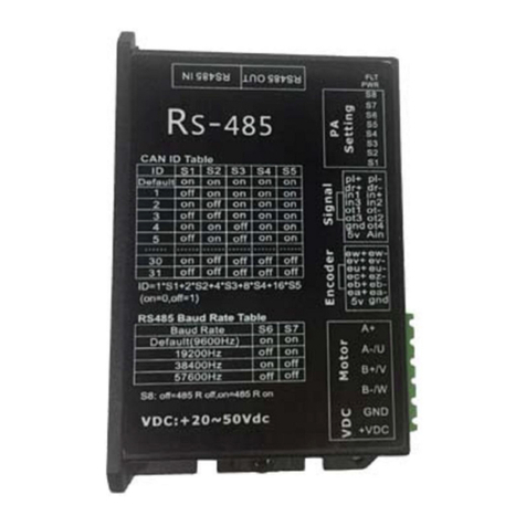
Desin Instruments DAS-8000 User manual

DAS-8000 ver. 2.5
Introduction / I2
Contents
CONTENTS...............................................................................................................2
INTRODUCTION ........................................................................................3
GENERAL DESCRIPTION ................................................................................................................... 4
PRESET CONFIGURATION.................................................................................................................5
INSTALLATION.......................................................................................... 6
PRECAUTIONS..........................................................................................................6
PRECAUTIONS IN THE ASSEMBLY AREA .........................................................................................6
PRECAUTIONS WHEN CONNECTING EQUIPMENT .............................................................................7
Connecting to the Main Power...................................................................................................7
Connecting the transducer input.................................................................................................8
Connection to Ground.................................................................................................................8
Digital serial communication. ....................................................................................................9
GENERAL PRECAUTIONS.................................................................................................................. 9
DIMENSION AND OPENINGS IN PANEL............................................................................................10
CONNECTIONS.......................................................................................................11
ANALOG INPUT CONNECTIONS.......................................................................................................11
ANALOG INPUTS MA. USING THE SAME POWER SUPPLY..............................................................12
Example using independent power supply...............................................................................12
Example using same power supply...........................................................................................12
DIGITAL INPUT CONNECTIONS .......................................................................................................13
DIGITAL OUTPUT CONNECTIONS....................................................................................................13
DESCRIPTION........................................................................................... 14
DISPLAY .........................................................................................................................................14
KEYBOARD.....................................................................................................................................15
CONNECTION TERMINALS..............................................................................................................16
ANALOG INPUT CONFIGURATION “JUMPERS”...............................................................................17
CONFIGURATION “JUMPER” OF COMMUNICATION TYPE ..............................................................18
Configuration of communication type......................................................................................18
INSTRUCTIONS FOR USE....................................................................... 19
MENU TREE.............................................................................................. 19
DISPLAY MENU...............................................................................................................................19
CONFIGURATION MENU.................................................................................................................22
DESCRIPTION OF DISPLAY MENU PARAMETERS .......................................................25
DISPLAYING THE SOFTWARE VERSION..........................................................................................25
MANUAL DISPLAY OF MODULE MEASUREMENTS. ........................................................................26
AUTOMATIC DISPLAY OF MODULE MEASUREMENTS....................................................................26
MANUAL DISPLAY OF THE MEASUREMENTS OF OTHER MODULES. .............................................27
AUTOMATIC DISPLAY OF MEASUREMENTS OF OTHER MODULES.................................................28
ALARM DATA DISPLAY...................................................................................................................29

DAS-8000 ver. 2.5
Introduction / I3
Manual alarm acknowledgment...............................................................................................30
How to see and/or modify the setpoint of an alarm..................................................................30
How to see and/or modify the hysteresis of an alarm...............................................................31
How to see and/or modify the status of alarm..........................................................................31
COUNTERS.............................................................................................................32
COUNTER DISPLAY ........................................................................................................................32
Displaying and/or changing the counter preset value ..............................................................33
PERFORMING A COUNTER RESET..................................................................................................34
PRINTING MEASUREMENTS AND/OR ALARMS OF DAS-8000 MODULES......................35
CONFIGURATION.................................................................................... 36
PASSWORD INPUT..........................................................................................................................36
SUMMARY OF CONFIGURATION PARAMETERS .............................................................................37
CALIBRATION.......................................................................................... 39
COMMUNICATIONS................................................................................ 39
TYPES OF COMMUNICATIONS..................................................................................39
DAS-8000 NETWORK IN RS-485...................................................................................................39
RS-232 COMMUNICATIONS WITH A PC..........................................................................................40
RS-485 COMMUNICATIONS WITH A PC.........................................................................................40
RS-232 PRINTER COMMUNICATIONS ............................................................................................40
MAINTENANCE........................................................................................ 41
DISPLAY MESSAGES CODES ...........................................................................................................41
LOCATING FAILURES ..............................................................................................42
ATENTION:
•WE STRONGLY RECOMMEND YOU TO
READ THIS INSTRUCCIONS CAREFULLY
BEFORE MANIPULATING THE DAS-8000.
•In this Quick Guide is explained, in an abridged manual, as
the DAS-8000 must be used. The instructions to configure,
calibrate, communications and others informations about
DAS-8000, are given separately, in the “User’s manual”,
edited in CD-ROM in ACROBAT PDF format.

DAS-8000 ver. 2.5
Introduction / I4
Introduction
General description
The DAS-8000 module is a digital and analog signal acquisition
device, which can function in an autonomous way, or supervised by an
intelligent system (PC, PLC, etc.).
It accepts up to 8 analog inputs configurable for Pt-100, 0..4-20
mA., 0..10-50 mV and 8 thermocouples for 4-20 mA. Inputs from
non- linearized converters, (E, J, K, T, S, R, B and N).
It has 8 digital inputs to capture logical data (Alarm recognition
push-buttons, contacts, proximity detectors, etc.), and also has 8 digital
outputs, that can be used as alarm outputs of the analog inputs, or
controlled via remote control by communication with the central unit.
The DAS-8000 module has a detachable front panel with a
display and keyboard for monitoring measurements. It can also function
without the front panel, and is able to display data from other DAS-8000
modules, through the communications bus or supervisory PC.
This multifunction terminal can be removed from the main body,
which allows you to mount it in the front panel, placing the main block
of the DAS-8000 on the back as endpoint connection of the signal lines.

DAS-8000 ver. 2.5
Introduction / I5
Communication among DAS-8000 modules is performed in
RS-485 protocol, enabling the connection of a maximum of 32
instruments in the same communications line (it can reach 255 units
using preamplifiers or RS-485 multiplexes). Thereby, it is possible to
achieve a high level of immunity from electrical noise and industrial
parasites.
One selectable serial port are available for communications with
the Supervisory PC:
•RS-232 When you have only one DAS-8000 at a distance of less
than 15 meters.
•RS-485 If there are two or more DAS-8000 modules in the network
at a distance of over 15 meters (maximum 1200 m.).
It has a second RS-232 channel specifically for the connection of
a serial printer. Data and measurements in tabular format are sent via
this channel to generate printed reports, either manually or
automatically, at a predefined time.
The management of the data and measurement acquired by the
DAS-8000 modules, from a PC, is handled by the PROASIS DAS-Win
software program, that is a SCADA application under Windows,
composed of a series of supervision and control programs for industrial
processes.
Preset Configuration
Each DAS-8000 module is supplied with a standard
configuration. This configuration is totally modifiable by the user.
See chapter “Instructions for Use” in the User’s Manual.

DAS-8000 ver. 2.5
Installation / I6
Installation
Precautions
NOTE:
•This equipment complies European Security
Standards and ECM requirements. Nevertheless, it
is responsibility of the installer to ensure the
continuity of the fulfilment of this regulation for the
rest of the installation.
The elementary installation standards for equipment controlled by
a microprocessor, can be outlined in specific assembly precautions and
general precautions in the electrical installation. The descriptions of
such precautions are outlined in the following sections.
Precautions in the Assembly Area
•Avoid direct, intense sources of light.
•Find a location free of corrosive vapours, leaks, humidity, large
vibrations, etc.
•Keep the temperature around the instrument from exceeding 50°C.
•Stay away from sources of electromagnetic radiation, high tension
radio frequencies, microwaves, etc.

DAS-8000 ver. 2.5
Installation / I7
Precautions when connecting equipment
Before connecting to the electrical power or inputs and outputs,
study carefully the wiring data.
It is advisable to carry out the wiring as much as possible
according to the recommendations outlined below.
IMPORTANTS NOTES:
•DO NOT APPLY INPUT VOLTAGES OVER 5 Vdc DIRECTLY
TO THE ANALOG INPUTS !!!
Take special care when connecting 0..4-20 mA. signals to the analog
inputs, since if a 2.5 ΩSHUNT resistor is broken, has a false contact
or simply is not connected in parallel to the analog channel input,
this channel will receive the 0..4-20 mA loop power supply voltage
(generally 12 or 24 Vdc) directly, thus damaging the input circuit.
•If you will be measuring a signal of more than 50 mV, use a voltage
divider at the channel input.
•An inadequate installation would leave the module exposed to
transitory and parasite current of the power grid, that would be
evidenced by frequent blinking in the display with a momentary
display of the initialization message, or of a supposed line
breakdown ERR 1).
•To protect the module and the process being supervised, the circuit
has a security system called Watch-Dog, that detects any anomaly
in the functioning of the microprocessor, caused by parasite current
in the lines, re-establishing the standard status immediately after the
error message.
Connecting to the Main Power.
•The electrical power of the modules should be as direct as possible
from the general distribution panel, with a star-shaped distribution
(to avoid the electrical power in parallel with other electrical
equipment).
•Avoid the electrical power of the coils of the relays, contacts, etc., by
not using the same network line as the instruments.
•In the event of a very disturbed network (due to power units,
resistances for example), feed the instrumentation part through an
insulation transformer, with the screen connected to ground.

DAS-8000 ver. 2.5
Installation / I8
Connecting the transducer input.
•Separate physically throughout the whole trajectory, the signal lines
(Pt-100, mA, mV), from the power lines or command relays,
contacts, servomotors, actuators, etc.
•Use different and independent channels and conductors.
•For large signal line lengths, use cables with twisted and shielded wires.
IMPORTANT NOTE:
The screen should be connected to the ground at a single point pertaining to
the reception area of the signal, in other words, a ground terminal near the
instrument.
DO NOT CONNECT TO GROUND THE 2 END POINTS OF THE
SHIELD.
•For Pt-100 inputs: Use 3-wire copper cable to compensate for the
errors caused by the parasite resistances of the connection cables of
the probe (use a section of 1.5 mm2 minimum).
•For mV inputs: Use copper cable of 1.5 mm2in section as a
minimum. Respect the polarity.
•For mA inputs: Use copper cable of 1.5 mm2in section as minimum.
Respect the polarity and add in parallel with the input terminals a
Shunt resistance of 2.5 Ohms (that are included with the module).
Connection to Ground.
•The DAS-8000 modules do not have ground connections due to the total
absence of metallic parts in their housing. Nevertheless, it is advisable to
place near the module some general ground terminal to connect the shield
screens of the connection or signal communication cables.
•In any installation, the ground terminals of the modules should be joined
in the shape of a star on one point of the installation (metallic mass),
with a conductor from the same section as the electrical power wires.

DAS-8000 ver. 2.5
Installation / I9
Digital serial communication.
The connection of the communications must be done with twisted
and shielded cable. The shield should also be connected to ground.
General precautions
•Before connecting to the electrical power grid, or inputs and outputs,
examine carefully the connection data label.

DAS-8000 ver. 2.5
Installation / I10
Dimension and openings in panel.
Box of nonflammable thermal plastic.
Weight of the complete instrument: 710 g.
Weight of the display alone: 76 g.

DAS-8000 ver. 2.5
Installation / I11
Connections.
Analog input connections
Analog
input Input
Pt-100 Input
mV. Input
mA.
Channel 1 1= +
2= -
3= ⊥
1= +
2= -
3= ⊥
1= +
2= -
3= ⊥
(SHUNT resistance of 2,5 W)
Channel 2 3= ⊥
4= -
5= +
3= ⊥
4= -
5= +
3= ⊥
4= -
5= +
(SHUNT resistance of 2,5 W)
Channel 3 6= +
7= -
8= ⊥
6= +
7= -
8= ⊥
6= +
7= -
8= ⊥
(SHUNT resistance of 2,5 W)
Channel 4 8= ⊥
9= -
10= +
8 = ⊥
9 = -
10= +
8 = ⊥
9 = -
10= +
(SHUNT resistance of 2,5 W)
Channel 5 11= +
12= -
13= ⊥
11= +
12= -
13= ⊥
11= +
12= -
13= ⊥
(SHUNT resistance of 2,5 W)
Channel 6 13= ⊥
14= -
15= +
13= ⊥
14= -
15= +
13= ⊥
14= -
15= +
(SHUNT resistance of 2,5 W)
Channel 7 16= +
17= -
18= ⊥
16= +
17= -
18= ⊥
16= +
17= -
18= ⊥
(SHUNT resistance of 2,5 W)
Channel 8 18= ⊥
19= -
20= +
18= ⊥
19= -
20= +
18= ⊥
19= -
20= +
(SHUNT resistance of 2,5 W)

DAS-8000 ver. 2.5
Installation / I12
Analog Inputs mA. Using the same power supply
In the case of mA. Signals coming from 2-wire transmitters
powered with the same 24 Vdc power supply and are connected to the
analog inputs of DAS-8000 module, the Shunt resistances of 2.5 Ω
should be connected between positive (+) and ground (⊥⊥) terminals,
instead of positive (+) and negative (-) terminals.
Example using independent power supply
Connection of two 4-20 mA. Signals coming from 2-wire
transmitters to two analog inputs of the DAS-8000 module, powered
with independent power supply.
Example using same power supply
Connection of two 4-20 mA. Signals coming from 2-wire transmitters to
two analog inputs of the DAS-8000, powered with the same power supply.
24 Vdc
24 Vdc
Shunt= 2.5 Ω
Shunt= 2.5 Ω
24 Vdc
Shunt= 2.5 Ω
Shunt= 2.5 Ω

DAS-8000 ver. 2.5
Installation / I13
Digital input connections
The digital inputs allow you to detect HI logical signals between
12 and 48 volts, either in AC or DC.
Digital Input Terminals
Digital input 1 49 50
Digital input 2 51 52
Digital input 3 53 54
Digital input 4 55 56
Digital input 5 57 58
Digital input 6 59 60
Digital input 7 61 62
Digital input 8 63 64
NOTE: The digital Inputs don’t have polarity.
Digital output connections
The digital output consist of an NPN transistor in an open
collector, optically insulated and free of potential, allowing the
switching of 100 mA loads with an external voltage of 48 VDC
maximum.
Digital Output Terminals
Digital Output 1 33= - 34= +
Digital Output 2 35= - 36= +
Digital Output 3 37= - 38= +
Digital Output 4 39= - 40= +
Digital Output 5 41= - 42= +
Digital Output 6 43= - 44= +
Digital Output 7 45= - 46= +
Digital Output 8 47= - 48= +

DAS-8000 ver. 2.5
Description / I14
Description
The DAS-8000 has, in its complete version, a multifunction,
detachable terminal, for data monitoring and parameter configuration.
The display and keyboard are described in the following paragraphs.
Display
The data display is composed of 2 indicators of different sizes of 4
digits each, and also two 8 + 8 LED blocks:
•1) The main indicator (upper) consists of 4 green digits, 14 mm.
high. It indicates the process value, the messages, and the
configuration variables.
•2) The secondary indicator (lower), has 4 red digits, 7 mm. high.
It indicates the channel number that is being displayed, the module
number, and configuration messages.
•3) 8 LED, for the indication of activation or deactivation of the
Digital Inputs (Lit = ON).
•4) 8 LED, for the indication of activation or deactivation of the
Alarms (Lit =ON).

DAS-8000 ver. 2.5
Description / I15
Keyboard
The keyboard of the removable terminal of the DAS-8000,
consists of 4 keys situated under the LED, with the following functions:
•5) FUNCTION / ESCAPE KEY.
It has two functions:
- allows access to read the different channels, parameters, etc. of the
display and configuration menus.
- allows you to exit in any branch of the menu tree.
•6) INCREMENT KEY.
It has two functions:
- Increments the value of the digit that is blinking (editing of the
value), or selects menu positions.
- Allows manual printing.
•7) SHIFT KEY.
It has two functions:
- Allows you to select the digit to be edited, moving it to the left,
enabling you to modify the value of a parameter with the Increment key.
- Activates/Deactivates the automatic scanning mode of analog inputs.
•8) VALIDACIÓN KEY (ENTER).
It has two functions:
- Saves the value that has been modified with the Increment and
Shift key.
- Allows you to introduce the module number to be displayed.

DAS-8000 ver. 2.5
Description / I16
Connection terminals
The DAS-8000 module has 2 rows of disconnectable terminals for
wires of 2 mm. diameter.
In the upper row, there are analog inputs connections consisting
of 8 blocks of two terminals (+ and -) for mV or mA with shunt, sharing
a third terminal, centered between every two channels, for line
compensation in Pt-100 inputs.
It also has three terminal blocks for communications and a
separate block for connection to the main power grid.
In the lower row, there are the digital input and output
connections composed of two blocks of 8 channels with two terminals
each one.

DAS-8000 ver. 2.5
Description / I17
Analog input configuration “Jumpers”.
The DAS-8000 module allows you to configure from the keyboard
RTD (Pt-100) or LINEAR (10-50 mV, 4-20 mA, 0-20 mA or Non-
linearized thermocouples) signals, because they are shipped already
calibrated. The adaptation of the input terminals for each type of signal
depends on the positions of the internal jumpers of each channel.
When opening a DAS-8000 module and removing the cover, you
will notice on the printed circuit board, on the side of the components,
the layout of the jumpers for configuration of the analog channels, just as
you see them in the following picture:
Each of the 8 channels has one disconnectable, black jumper, that
should be connected according to the type of sensor used, as indicated in
the following figure:
Pt-100 INPUT.
LINEAR INPUT. 10-50 mV.
4-20 mA, 0-20 mA, Non-linearized thermocouples.
(With SHUNT resistance of 2’5 W in parallel with input
terminals).
POWER
SUPPLY
“jumpers”
Ch 2
“jumpers
Ch 1“jumpers”
Ch 7
“jumpers”
Ch 3
“jumpers”
Ch 4
“jumpers”
Ch 5
“jumpers”
Ch 6“jumpers”
Ch 8
Port Selection
RS-232 / RS-485

DAS-8000 ver. 2.5
Description / I18
Configuration “Jumper” of communication type
To locate the “Jumper” of the DAS-8000 related to the
modification of the communications type, you need to access the circuit
from the components side.
Locate the strap visually, just as you see them in the following
picture (visually make sure the printed circuit number on the lower right
side corresponds to the C/477-4 code):
Configuration of communication type
J1 Jumper: Setting pin layout for RS-232 or RS-485 output terminals.
The position of this “Jumper” allows you to select the RS-232 or
RS-485 standard of communication, between the DAS-8000 module and
the PC, determining at the same time the output terminals:
21, 22, and 23 for RS-232, or 26, 27, and 28 for RS-485.
S2: Don´t Use
4020M
POWER
SUPPLY
J1: Selection Port “Jumper”
RS-232 / RS-485
C/474-4
Circuit Number
RS-485 RS-232

DAS-8000 ver. 2.5
Instructions for use / I19
Instructions for use
Menu tree
The operation of the DAS-8000 in its operational level, both in
standard use, as well as in configuration, is based on 2 menus that allow
you to have access to the totality of DAS-8000 functions:
•Display menu: It is the main operation menu, and the one that will
be most frequently used. With it, you can access the viewing of the
analog measurements and alarm parameter modification of the
module being used, or of any another connected to the same
communication network.
•Configuration menu: This menu allows you to access the
parametrization and configuration of all the DAS-8000's available
options. Access to the Configuration Menu is protected by means of
the access password.
The following is a description of the two menus.
Display menu
The Display Menu appears when you start the module, allowing
you to display the 8 measurements received by the analog channels,
change the parameters most frequently changed in the configuration of
alarms, setpoint, hysteresis, and status, (Password Alarm is required to
enabled the access to alarm menu) and display the 2 counters.
The last level of the menu (PASS) requests the access Password to
enter the configuration menu.
The diagram of operation of the Display Menu is shown in the
following figure:

DAS-8000 ver. 2.5
Instructions for Use / I20
DISPLAY MENU
Change of
Module to
Display
Display
Channel 1
Display
Channel 2
Display
Channel 3
Display
Channel 4
Display
Channel 5
Display
Channel 6
Display
Channel 7
Display
Channel 8
Start
X X X X
6
X X X X
7
X X X X
8
X X X X
4
X X X X
5
X X X X
2
M O
x x
x
X X X X
1
X X X X
3
Table of contents

