Destination Audio SP4-50 User manual
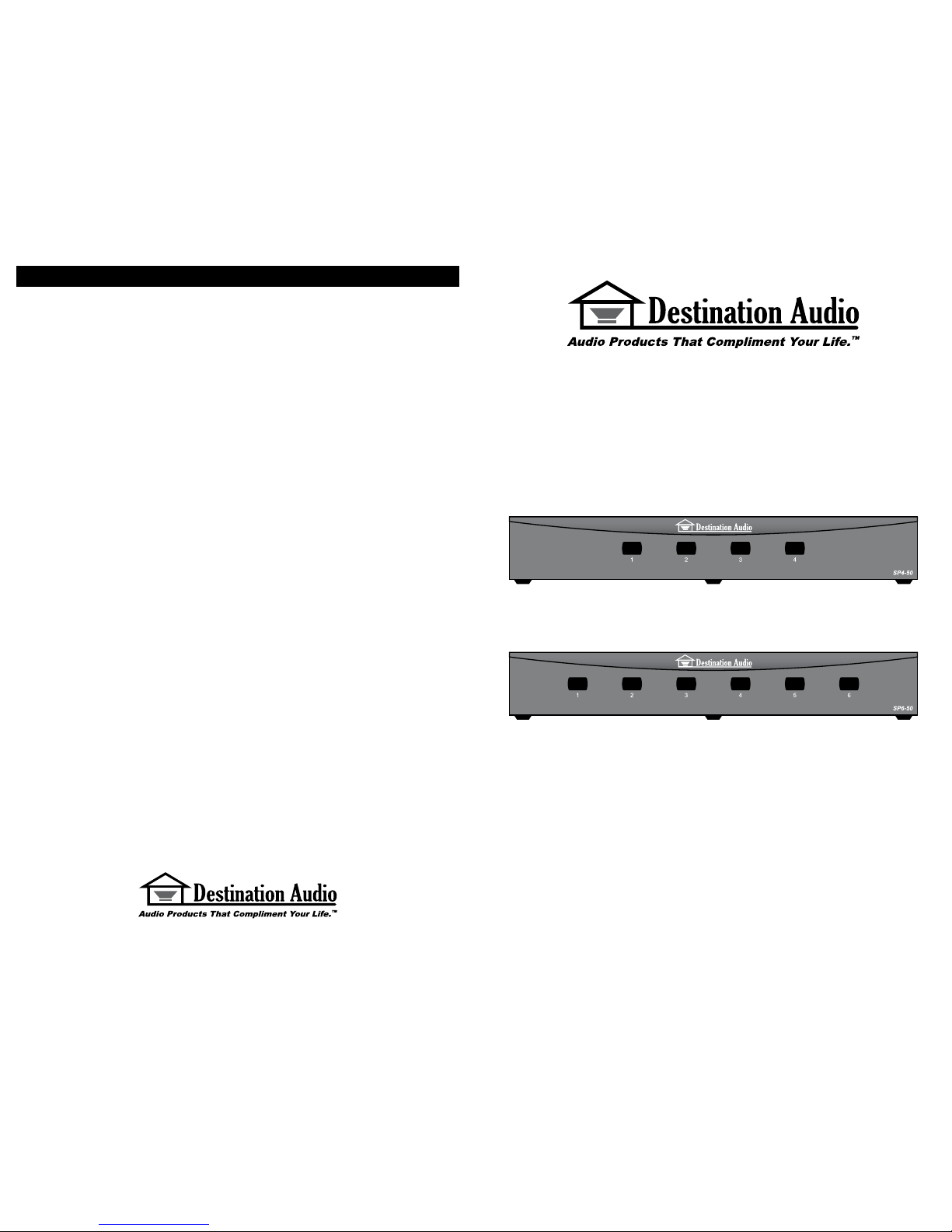
SP4-50
SP6-50
4-Channel and 6-Channel
Impedance Matching Speaker Selectors
Installation & Operation Manual
382 Marshall Way • Layton, Utah • USA • 84041
Toll-free: (800) 543-2205 • Fax: (801) 543-3300
www.destinationaudio.com
It is Destination Audio policy to continuously incorporate improvements into our products; all specications are subject to change without notice.
Copyright © 2006, Destination Audio. All Rights Reserved.
Warranty
Destination Audio warrants the SP4-50 / SP6-50 to be free from defects in materials and workmanship
(subject to the terms set forth below) for a period of ten (10) years from the date of purchase. During
the Warranty period, Destination Audio will repair or replace (at Destination Audio’s option) this product
or any defective parts (excluding electronics and ampliers).
To obtain Warranty service, please contact the Destination Audio authorized dealer from which you
purchased this product. If your dealer is not equipped to perform the repair of your Destination Audio
product, it can be returned, freight prepaid, to Destination Audio for repair. Please call Destination Audio
at 800-543-2205 for instructions. You will need to ship this product in either its original packaging or
packaging affording an equal degree of protection.
Proof of purchase in the form of a bill of sale or receipted invoice, which is evidence this product is
within the Warranty period, must be presented or included to obtain Warranty service.
This Warranty is invalid if (a) the factory-applied serial number has been altered or removed from this
product or (b) this product was not purchased from an Destination Audio authorized dealer. You may
call 800-543-2205 to conrm that you have an unaltered serial number and/or you purchased from an
Destination Audio authorized dealer.
This Warranty does not cover cosmetic damage or damage due to misuse, abuse, negligence, acts of
God, accident, commercial use or modication of, or to any part of, the product. This Warranty does not
cover damage due to improper operation, maintenance or installation, or attempted repair by anyone
other than Destination Audio or a Destination Audio dealer which is authorized to do Destination Audio
warranty work. Any unauthorized repairs will void this Warranty. This Warranty does not cover product
sold AS IS or WITH ALL FAULTS.
REPAIRS OR REPLACEMENTS AS PROVIDED UNDER THIS WARRANTY ARE THE EXCLUSIVE
REMEDY OF THE CONSUMER. DESTINATION AUDIO SHALL NOT BE LIABLE FOR ANY INCIDENTAL
OR CONSEQUENTIAL DAMAGES FOR BREACH OF ANY EXPRESS OR IMPLIED WARRANTY
ON THIS PRODUCT. EXCEPT TO THE EXTENT PROHIBITED BY LAW, THIS WARRANTY IS
EXCLUSIVE AND IN LIEU OF ALL OTHER EXPRESS AND IMPLIED WARRANTIES WHATSOEVER,
INCLUDING BUT NOT LIMITED TO, THE WARRANTY OF MERCHANTABILITY AND FITNESS FOR
A PRACTICAL PURPOSE.
Some states do not allow the exclusion or limitation of incidental or consequential damages or implied
warranties so the above exclusions may not apply to you. This Warranty gives you specic legal rights,
and you may have other rights, which vary from state to state.

Thank you!
Congratulations on your purchase of a Destination Audio SP4-50 / SP6-50 Speaker Selector!
Your speaker selector has been designed to deliver years of worry-free music, enjoyment and
satisfaction. Your speaker selector is the result of many years of research and development
dedicated to producing high quality products for home audio and audio/video systems.
Please keep this manual in a safe place in case you need to refer to it at a later date. Our
installation considerations should be used as a guide for those with and without experience
installing impedance matching volume controls. If at any point you have questions regarding
the connection and installation of this speaker selector please contact technical support at
(800) 543-2205.
Contents
Specications.........................................................................................................1
Introduction / Features...........................................................................................2
Technology.............................................................................................................2
Benets..................................................................................................................3
Installation Considerations.....................................................................................3
Recommended Setup.............................................................................................4
Installation Instructions...........................................................................................5
System Diagrams...................................................................................................6
Warranty.................................................................................................Back cover
Contact Information................................................................................Back cover
Specications
SP4-50 SP6-50
Selector Type: Push Button Push Button
Frequency Response (±3dB): 20Hz - 20kHz 20Hz - 20kHz
Power Handling (per channel): 50 Watts RMS 50 Watts RMS
Maximum Speakers Supported: 4 pairs / 4Ω min. 6 pairs / 4Ω min.
Wire: 16 AWG to 14 AWG 16 AWG to 14 AWG
Dimensions (W x H x D):11½” x 2” x 7” 11½” x 2” x 7”
292mm x 51mm x 178mm 292mm x 51mm x 178mm
Weight: 2.65 Lbs. 2.70 Lbs.
System Diagrams
System 1 — SP4-50
This system uses one stereo receiver/amplier, one SP4-50 and four pairs of speakers: two remote
pairs using Destination Audio volume controls and two local pairs wired directly to the SP4-50.
System 2 — SP6-50
This system uses one stereo receiver/amplier, one SP6-50 and six pairs of speakers, all
using Destination Audio volume controls.
1 6
Introduction / Features
SP4-50
The SP4-50 is a resistor-based, impedance-matching* speaker selector for connecting up
to four pairs of 4Ω to 8Ω (Ohms) speakers to a stereo receiver or amplier. The SP4-50
features include on/off selection on each of four outputs, a small footprint, detachable 14
AWG speaker connections and simple operation at an affordable price. The audio resistors
chosen offer great sound quality and long-lasting, safe operation. Each component chosen
in the Destination Audio SP4-50 was chosen for its reliability and value. Use the SP4-50
in small residential, light commercial, restaurants and other sound systems where light
background music is needed. The SP4-50 can be used with Destination Audio Volume
Controls: VC-50R, VC-50S, VC-100R, VC-100S and VC-100RW. Refer to those product
manuals for proper setup involving impedance matching volume controls.
SP6-50
The SP6-50 is a resistor-based, impedance-matching* speaker selector for connecting up
to six pairs of 4Ω to 8Ω speakers to a stereo receiver or amplier. All features are the same
as the SP4-50. Refer to the above SP4-50 introduction for more details.
Technology
The SP4-50 / SP6-50 speaker selectors utilize mechanical audio switches to turn on and off
pairs of speakers connected to the respective switch. Each switch is connected to an audio
resistor which maintains sound quality while protecting the amplier from low impedance
failure. The resistors can get hot and problems can arise from overpowering resistor-based
speaker selector products. Resistor-based speaker selectors are commonly misused and
it is important to understand how to use this product properly. This product is designed to
play at moderate volume levels and is rated at 50 Watts per channel. If you desire higher
volumes at longer intervals with all pairs on, speaker selectors are not recommended. An
example would be bars, lounges or dance clubs where the music would be playing at high
volume with a lot of power for long periods of time.
Impedance Matching / Impedance Protection
A typical home stereo receiver or amplier operates at 8Ω. The lower the impedance, the
harder the system works, and eventually the amplier will no longer operate. Impedance
Matching / Impedance Protection* is used to present safe operating loads when connecting
multiple pairs of speakers to an amplier. Each output of the SP4-50 / SP6-50 is meant to be
connected to a minimum of a pair of 4Ω speakers. See your speaker and amplier specications
for the normal operating impedances as you will need to know them later. Contact the
manufacturer if you are unsure or uncertain of the nominal impedance of your speakers.
* When used with a 4Ω stable amplier.
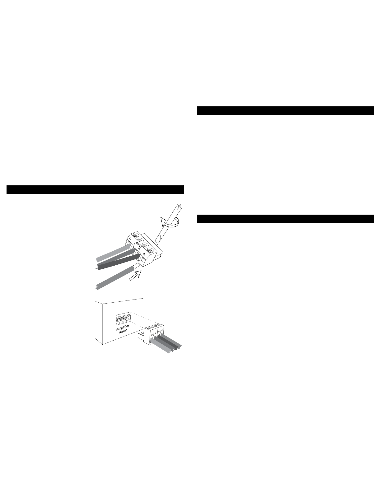
Speaker Wire Connections
Connect the Left and Right speaker output of the amplier to the Left and Right speaker input
of the SP4-50 / SP6-50. The wire connection should be made with 16 AWG or 14 AWG,
4-conductor speaker wire. Strip off ¼-inch (7mm) of the insulation from the end of each
conductor and twist the strands so there are no frayed ends. Insert the wire into the detachable
connector, making sure of the correct polarity. Using a small, standard-head screwdriver,
tighten the screw down on the wire, making certain no exposed strands or frayed ends of
the wire are visible. Repeat until all connections are made and check the security of the
connection before inserting the connector into the SP4-50 / SP6-50.
All Destination Audio volume controls have impedance matching capabilities which become
redundant in this application. Use the 1X setting (or 2X setting when 1X isn’t available) on
all controls when connecting to the SP4-50 / SP6-50 as all impedance protection is built
within the speaker selector and not necessary within the volume control.
Installation Instructions
Installing the SP4-50 / SP6-50
1. Run wire from the stereo receiver or
amplier to the SP4-50 / SP6-50 and out
to the volume controls/speakers.
2. Strip a ¼-inch (7mm) of insulation from
the end of the wires. Connect the wires
to the removable connector plugs using a
small, standard-head screwdriver (see
Figure 1). The plugs are labeled to
simplify installation.
3. Set the impedance switch on the volume
control(s). When using Destination Audio
impedance matching volume controls, set
the impedance multiplier switch to 1X (or
2X when 1X isn’t available).
4. Install the connectors to the SP4-50 /
SP6-50 (Figure 2).
5 2
Figure 1
Figure 2

Benets
• Connect and control multiple pairs of speakers safely with only one amplier
• Designed to t into the audio equipment cabinet or rack
•Years of worry-free operation
• Clean switching and acoustically-accurate sound reproduction
• High reliability
• Quality construction
• Easy installation
• Easy ON / OFF control of speakers
Installation Considerations
Wiring Requirements
For most applications, it is recommended you use a minimum of a 16 AWG stranded copper
speaker wire; never use a wire gauge below 18 AWG. The higher the number gauge (AWG),
the smaller the wire. Performance will suffer when using smaller wire gauges. Always use
stranded wire rated for in-wall usage; the wire jacket should specify a CL re rating. Building
codes usually require a CL-2 or CL-3 rating, which makes it safe enough for installation inside
walls. You will need a total of 4 conductors (two sets of two individual wires) from your amplier
to the SP4-50 / SP6-50 input, and 2 conductors (one set of two individual wires) from each
left and right output to each speaker location. Another option is to use a 4 conductor wire
to an impedance-matching volume control location, and then a 2 conductor wire to each
speaker location. Destination Audio suggests you check your local building code requirements
regarding the use of such wire types before using them. Electricians, Custom A/V Integrators
and Electrical Inspectors are great resources regarding this subject; they are also great at
installing such devices. If, at any time, you feel uncomfortable with wiring, connecting or
choosing locations, please consult with a professional.
New Home Construction Precautions
Wiring and installing volume controls is easier when the walls are free of insulation and prior
to drywall installation. It is important that precautions are taken to avoid system failures. It
is recommended that when you are wiring your open walls, you are aware of the potential
hazards and the tools and hardware required to avoid them. Nails, screws and accidentally
cut or exposed wire can cause system failure. Local hardware stores sell nail guards which
cover the stud where the speaker wire passes through. Using nail guards will almost guarantee
a drywall or nish nail or screw won’t damage the speaker wire.
Do not share holes in studs with electrical, alarm or unrelated low voltage wires. Only drill
the size hole necessary to feed the wire through easily. DO NOT RUN SPEAKER WIRE
PARALLEL WITH ELECTRICAL ROMEX WIRE. Locating speaker wires too close to electrical
wires and devices can result in undesired noises such as buzzing, humming and popping
through the speakers. It is okay to cross electrical wires when necessary, but do so minimally,
and at a minimum of a 45° angle; if possible, try to have speaker wires cross high-voltage
wires at a 90° angle to avoid the noises described above. When at all possible, try to keep
speaker wires a minimum of 18-inches from electrical wires and devices. Following these
simple precautions will help prevent noise from an electrical device. Secure the speaker
wire to the stud as close to the center of the stud bay as possible, using insulated staples, tie
(continued on next page)
New Home Construction Precautions (continued)
wraps or a secure method which won’t damage the jacket of the wire; if using staples, be
careful not to damage the wire. Be careful while installing the wire in the walls; try not to use
excessive force. Try to use less than 8-10 Lbs. of force when pulling the wire, and avoid
radically bending the wire to the point where damage can occur. Be sure to label wires at
both ends and protect those labels and ends from damage or drywall mud and paint. Labelling
wire is always a good practice, and can save signicant time during the nal setup of your
system. Make sure to leave an appropriate length in each location, making installation easy,
clean and neat.
Retro-tting an Existing Home
Wiring and installing audio systems in an existing home can be difcult. If you are unfamiliar
with the tools required to feed wire through existing walls and ceilings, it is highly
recommended you consult an Electrician, low-voltage installer or Custom A/V Integrator for
your installation needs. Likewise, if you are unfamiliar with the construction methods of the
home, please consider professional assistance.
Warning
Always turn off the amplier when connecting volume controls, speakers or any other
components in the system. Only professionals should perform the installation of these
devices or those possessing skills in construction, experience with the proper use of hand
tools, knowledge of local building and electrical codes, and familiarity with the environment
in which the product(s) will be installed. Install all products to meet all local building, energy
and electrical codes.
SP4-50 / SP6-50 Recommended Setup
Impedance and Wattage Considerations
Due to the nature of this type of impedance protection device, it is important to understand
that the impedance will change as speakers are turned on and off. You will notice as more
speakers are switched ON, the lower the volume. As each speaker is switched ON, the
impedance present at the amplier is decreased. The minimum impedance should never
fall below 4Ω if: (a) the proper number of speakers are used; and (b) the minimum speaker
impedance is 4Ω. When using an 8Ω stable amplier, it is suggested that only 2 pairs (2
switches) be on at any time to maintain the proper minimum amplier impedance. Destination
Audio highly recommends the use of a 4Ω stable amplier or stereo receiver. Contact the
manufacturer if you are unsure of your amplier’s minimum operating impedance. It is
important to select the proper stereo receiver / amplier for your system. It is suggested you
do not use the same stereo receiver / amplier as your main home theater / A/V system, as
your overall system performance will be effected in surround modes. It is important that no
more than 50 Watts per channel RMS be used. It is also important not to send clipped or
distorted signals through the SP4-50 / SP6-50; the result will be overheating of the resistors
and possible damage to the unit and/or the stereo receiver or amplier.
3 4
This manual suits for next models
3


