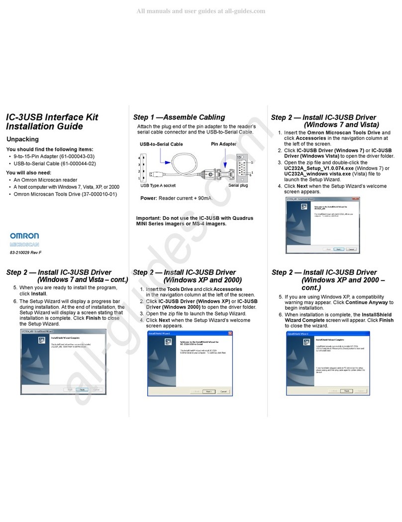
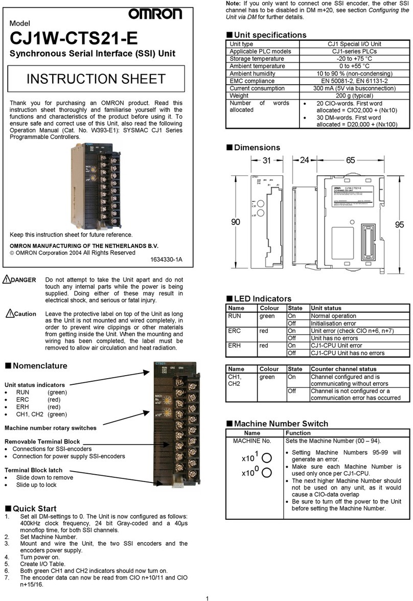
Omron Q2A-A Series Installation instructions

Q2A
Driving Quality
Installation & Operation Instructions
Item code: Q2A-Axxxx-xxx
200 V class 0.55 kW to 110 kW
400 V class 0.55 kW to 315 kW

This Page Intentionally Blank
2TOMPYEUOQ2A03C AC Drive Q2A Installation and Operation Instructions

TOMPYEUOQ2A03C AC Drive Q2A Installation and Operation Instructions 3
Table of Contents
1. English . . . . . . . . . . . . . . . . . . . . . . . . . . . . . . . . . . . . . . . . . . . . . . . . . . . . . . . 7
General Information. . . . . . . . . . . . . . . . . . . . . . . . . . . . . . . . . . . . . . . . . . . . . . . . . . . . . . . . 7
Qualifications for the Intended User . . . . . . . . . . . . . . . . . . . . . . . . . . . . . . . . . . . . . . . . . . . 7
Safety . . . . . . . . . . . . . . . . . . . . . . . . . . . . . . . . . . . . . . . . . . . . . . . . . . . . . . . . . . . . . . . . . . . 7
General Safety Instructions . . . . . . . . . . . . . . . . . . . . . . . . . . . . . . . . . . . . . . . . . . . . . . . . . . 7
Intended Use . . . . . . . . . . . . . . . . . . . . . . . . . . . . . . . . . . . . . . . . . . . . . . . . . . . . . . . . . . . . . 9
Exclusion of Liability . . . . . . . . . . . . . . . . . . . . . . . . . . . . . . . . . . . . . . . . . . . . . . . . . . . . . . . . 9
Moving the Drive . . . . . . . . . . . . . . . . . . . . . . . . . . . . . . . . . . . . . . . . . . . . . . . . . . . . . . . . . . 9
User Interface Elements . . . . . . . . . . . . . . . . . . . . . . . . . . . . . . . . . . . . . . . . . . . . . . . . . . . 10
Keypad Mode and Menu Displays. . . . . . . . . . . . . . . . . . . . . . . . . . . . . . . . . . . . . . . . . . . . .11
Mechanical Installation . . . . . . . . . . . . . . . . . . . . . . . . . . . . . . . . . . . . . . . . . . . . . . . . . . . . 12
Installation Environment. . . . . . . . . . . . . . . . . . . . . . . . . . . . . . . . . . . . . . . . . . . . . . . . . . . . 12
Removing the Covers. . . . . . . . . . . . . . . . . . . . . . . . . . . . . . . . . . . . . . . . . . . . . . . . . . . . . . 13
Electrical Installation . . . . . . . . . . . . . . . . . . . . . . . . . . . . . . . . . . . . . . . . . . . . . . . . . . . . . . 13
Standard Connection Diagram . . . . . . . . . . . . . . . . . . . . . . . . . . . . . . . . . . . . . . . . . . . . . . 13
Control Circuit Wire Gauges and Tightening Torques . . . . . . . . . . . . . . . . . . . . . . . . . . . . 14
Drive Start-Up . . . . . . . . . . . . . . . . . . . . . . . . . . . . . . . . . . . . . . . . . . . . . . . . . . . . . . . . . . . 15
Setup Wizard . . . . . . . . . . . . . . . . . . . . . . . . . . . . . . . . . . . . . . . . . . . . . . . . . . . . . . . . . . . . 15
Drive Parameters. . . . . . . . . . . . . . . . . . . . . . . . . . . . . . . . . . . . . . . . . . . . . . . . . . . . . . . . . 15
Troubleshooting . . . . . . . . . . . . . . . . . . . . . . . . . . . . . . . . . . . . . . . . . . . . . . . . . . . . . . . . . . 18
Disposal . . . . . . . . . . . . . . . . . . . . . . . . . . . . . . . . . . . . . . . . . . . . . . . . . . . . . . . . . . . . . . . . 22
European Standards . . . . . . . . . . . . . . . . . . . . . . . . . . . . . . . . . . . . . . . . . . . . . . . . . . . . . . 22
CE Low Voltage Directive Compliance . . . . . . . . . . . . . . . . . . . . . . . . . . . . . . . . . . . . . . . . 23
Area of Use . . . . . . . . . . . . . . . . . . . . . . . . . . . . . . . . . . . . . . . . . . . . . . . . . . . . . . . . . . . . . . 23
Guarding against Debris . . . . . . . . . . . . . . . . . . . . . . . . . . . . . . . . . . . . . . . . . . . . . . . . . . . 23
Connect a Fuse to the Input Side (Primary Side) . . . . . . . . . . . . . . . . . . . . . . . . . . . . . . . . 23
EMC Directive. . . . . . . . . . . . . . . . . . . . . . . . . . . . . . . . . . . . . . . . . . . . . . . . . . . . . . . . . . . . 23
Install a Drive to Conform to the EMC Directive . . . . . . . . . . . . . . . . . . . . . . . . . . . . . . . . . 23
Enable the Internal EMC Filter. . . . . . . . . . . . . . . . . . . . . . . . . . . . . . . . . . . . . . . . . . . . . . . 24
Safe Disable Input . . . . . . . . . . . . . . . . . . . . . . . . . . . . . . . . . . . . . . . . . . . . . . . . . . . . . . . . 25
Safe Disable Specifications . . . . . . . . . . . . . . . . . . . . . . . . . . . . . . . . . . . . . . . . . . . . . . . . . 25
Safety Precautions . . . . . . . . . . . . . . . . . . . . . . . . . . . . . . . . . . . . . . . . . . . . . . . . . . . . . . . . 26
Using the Safe Disable Function . . . . . . . . . . . . . . . . . . . . . . . . . . . . . . . . . . . . . . . . . . . . . 26
2. Deutsch. . . . . . . . . . . . . . . . . . . . . . . . . . . . . . . . . . . . . . . . . . . . . . . . . . . . . . 28
Allgemeine Informationen . . . . . . . . . . . . . . . . . . . . . . . . . . . . . . . . . . . . . . . . . . . . . . . . . . 28
Anwenderzielgruppe . . . . . . . . . . . . . . . . . . . . . . . . . . . . . . . . . . . . . . . . . . . . . . . . . . . . . . 29
Sicherheit . . . . . . . . . . . . . . . . . . . . . . . . . . . . . . . . . . . . . . . . . . . . . . . . . . . . . . . . . . . . . . . 29
Allgemeine Sicherheitshinweise . . . . . . . . . . . . . . . . . . . . . . . . . . . . . . . . . . . . . . . . . . . . . 29
Bestimmungsgemäßer Gebrauch . . . . . . . . . . . . . . . . . . . . . . . . . . . . . . . . . . . . . . . . . . . . 31
Haftungsausschluss. . . . . . . . . . . . . . . . . . . . . . . . . . . . . . . . . . . . . . . . . . . . . . . . . . . . . . . 31
Bewegen des Frequenzumrichters. . . . . . . . . . . . . . . . . . . . . . . . . . . . . . . . . . . . . . . . . . . 31

4TOMPYEUOQ2A03C AC Drive Q2A Installation and Operation Instructions
Elemente der Benutzerschnittstelle . . . . . . . . . . . . . . . . . . . . . . . . . . . . . . . . . . . . . . . . . . . 32
Bedienteilbetriebsart und Menübildschirme . . . . . . . . . . . . . . . . . . . . . . . . . . . . . . . . . . . . . 33
Mechanische Installation . . . . . . . . . . . . . . . . . . . . . . . . . . . . . . . . . . . . . . . . . . . . . . . . . . . 34
Installationsumgebung. . . . . . . . . . . . . . . . . . . . . . . . . . . . . . . . . . . . . . . . . . . . . . . . . . . . . . 34
Entfernen der Abdeckungen . . . . . . . . . . . . . . . . . . . . . . . . . . . . . . . . . . . . . . . . . . . . . . . . . 35
Elektrische Installation . . . . . . . . . . . . . . . . . . . . . . . . . . . . . . . . . . . . . . . . . . . . . . . . . . . . . 35
Standard-Anschlussdiagramm . . . . . . . . . . . . . . . . . . . . . . . . . . . . . . . . . . . . . . . . . . . . . . . 35
Drahtquerschnitte beim Steuerkreis und Anzugsmomente . . . . . . . . . . . . . . . . . . . . . . . . . 37
Inbetriebnahme des Frequenzumrichters . . . . . . . . . . . . . . . . . . . . . . . . . . . . . . . . . . . . . . 37
Einrichtungsassistent . . . . . . . . . . . . . . . . . . . . . . . . . . . . . . . . . . . . . . . . . . . . . . . . . . . . . . . 37
FU-Parameter . . . . . . . . . . . . . . . . . . . . . . . . . . . . . . . . . . . . . . . . . . . . . . . . . . . . . . . . . . . . 38
Fehlerbehebung . . . . . . . . . . . . . . . . . . . . . . . . . . . . . . . . . . . . . . . . . . . . . . . . . . . . . . . . . . 40
Entsorgung . . . . . . . . . . . . . . . . . . . . . . . . . . . . . . . . . . . . . . . . . . . . . . . . . . . . . . . . . . . . . . 44
Europäische Normen. . . . . . . . . . . . . . . . . . . . . . . . . . . . . . . . . . . . . . . . . . . . . . . . . . . . . . . 45
Konformität mit der CE-Niederspannungsrichtlinie . . . . . . . . . . . . . . . . . . . . . . . . . . . . . . . 45
Einsatzort . . . . . . . . . . . . . . . . . . . . . . . . . . . . . . . . . . . . . . . . . . . . . . . . . . . . . . . . . . . . . . . . 45
Schutz gegen Fremdteilchen. . . . . . . . . . . . . . . . . . . . . . . . . . . . . . . . . . . . . . . . . . . . . . . . . 45
Anschließen einer Sicherung auf der Eingangsseite (Primärseite) . . . . . . . . . . . . . . . . . . . 45
EMV-Richtlinie . . . . . . . . . . . . . . . . . . . . . . . . . . . . . . . . . . . . . . . . . . . . . . . . . . . . . . . . . . . . 46
Installieren eines Frequenzumrichters gemäß EMV-Richtlinie . . . . . . . . . . . . . . . . . . . . . . 46
Aktivieren des internen EMV-Filters . . . . . . . . . . . . . . . . . . . . . . . . . . . . . . . . . . . . . . . . . . . 46
Eingang „Sicherer Halt“. . . . . . . . . . . . . . . . . . . . . . . . . . . . . . . . . . . . . . . . . . . . . . . . . . . . . 47
Spezifikationen für „Sicherer Halt“. . . . . . . . . . . . . . . . . . . . . . . . . . . . . . . . . . . . . . . . . . . . . 48
Sicherheitsvorkehrungen. . . . . . . . . . . . . . . . . . . . . . . . . . . . . . . . . . . . . . . . . . . . . . . . . . . . 48
Verwenden der Funktion „Sicherer Halt“. . . . . . . . . . . . . . . . . . . . . . . . . . . . . . . . . . . . . . . . 49
3. Français . . . . . . . . . . . . . . . . . . . . . . . . . . . . . . . . . . . . . . . . . . . . . . . . . . . . . . 51
Informations générales . . . . . . . . . . . . . . . . . . . . . . . . . . . . . . . . . . . . . . . . . . . . . . . . . . . . . 51
Qualifications de l’utilisateur visé. . . . . . . . . . . . . . . . . . . . . . . . . . . . . . . . . . . . . . . . . . . . . 51
Sécurité. . . . . . . . . . . . . . . . . . . . . . . . . . . . . . . . . . . . . . . . . . . . . . . . . . . . . . . . . . . . . . . . . . 51
Instructions générales de sécurité. . . . . . . . . . . . . . . . . . . . . . . . . . . . . . . . . . . . . . . . . . . . . 52
Utilisation prévue . . . . . . . . . . . . . . . . . . . . . . . . . . . . . . . . . . . . . . . . . . . . . . . . . . . . . . . . . . 54
Exclusion de responsabilité. . . . . . . . . . . . . . . . . . . . . . . . . . . . . . . . . . . . . . . . . . . . . . . . . . 54
Déplacement du variateur de vitesse. . . . . . . . . . . . . . . . . . . . . . . . . . . . . . . . . . . . . . . . . . 54
Éléments de l’interface utilisateur . . . . . . . . . . . . . . . . . . . . . . . . . . . . . . . . . . . . . . . . . . . . . 55
Affichages des Modes et Menus de la console numérique.. . . . . . . . . . . . . . . . . . . . . . . . . 56
Installation mécanique. . . . . . . . . . . . . . . . . . . . . . . . . . . . . . . . . . . . . . . . . . . . . . . . . . . . . . 57
Environnement d’installation . . . . . . . . . . . . . . . . . . . . . . . . . . . . . . . . . . . . . . . . . . . . . . . . . 57
Retrait des couvercles . . . . . . . . . . . . . . . . . . . . . . . . . . . . . . . . . . . . . . . . . . . . . . . . . . . . . . 58
Installation électrique. . . . . . . . . . . . . . . . . . . . . . . . . . . . . . . . . . . . . . . . . . . . . . . . . . . . . . . 58
Schéma de connexion standard . . . . . . . . . . . . . . . . . . . . . . . . . . . . . . . . . . . . . . . . . . . . . . 58
Dimensions des fils du circuit de commande et couples de serrage . . . . . . . . . . . . . . . . . 60
Démarrage du variateur de vitesse. . . . . . . . . . . . . . . . . . . . . . . . . . . . . . . . . . . . . . . . . . . . 60
Assistant de configuration . . . . . . . . . . . . . . . . . . . . . . . . . . . . . . . . . . . . . . . . . . . . . . . . . . . 60
Paramètres du variateur de vitesse . . . . . . . . . . . . . . . . . . . . . . . . . . . . . . . . . . . . . . . . . . . 60
Dépannage. . . . . . . . . . . . . . . . . . . . . . . . . . . . . . . . . . . . . . . . . . . . . . . . . . . . . . . . . . . . . . . 63
Traitement . . . . . . . . . . . . . . . . . . . . . . . . . . . . . . . . . . . . . . . . . . . . . . . . . . . . . . . . . . . . . . . 67
Normes européennes . . . . . . . . . . . . . . . . . . . . . . . . . . . . . . . . . . . . . . . . . . . . . . . . . . . . . . 68
Conformité à la directive basse tension CE. . . . . . . . . . . . . . . . . . . . . . . . . . . . . . . . . . . . . . 68
Zone d’utilisation . . . . . . . . . . . . . . . . . . . . . . . . . . . . . . . . . . . . . . . . . . . . . . . . . . . . . . . . . . 68
Protéger des débris. . . . . . . . . . . . . . . . . . . . . . . . . . . . . . . . . . . . . . . . . . . . . . . . . . . . . . . . . 68
Connecter un fusible au côtéentrée (côtéprimaire) . . . . . . . . . . . . . . . . . . . . . . . . . . . . . . . 68
Directive CEM. . . . . . . . . . . . . . . . . . . . . . . . . . . . . . . . . . . . . . . . . . . . . . . . . . . . . . . . . . . . . 68

TOMPYEUOQ2A03C AC Drive Q2A Installation and Operation Instructions 5
Installer un variateur conforme àla directive CEM . . . . . . . . . . . . . . . . . . . . . . . . . . . . . . . . 69
Activer le filtre CEM interne . . . . . . . . . . . . . . . . . . . . . . . . . . . . . . . . . . . . . . . . . . . . . . . . . . 69
Entrée d’arrêt de sécurité. . . . . . . . . . . . . . . . . . . . . . . . . . . . . . . . . . . . . . . . . . . . . . . . . . . . 70
Spécifications de mise en sécurité. . . . . . . . . . . . . . . . . . . . . . . . . . . . . . . . . . . . . . . . . . . . . 70
Précautions de sécurité. . . . . . . . . . . . . . . . . . . . . . . . . . . . . . . . . . . . . . . . . . . . . . . . . . . . . . 71
Utilisation de la fonction d’arrêt de sécurité. . . . . . . . . . . . . . . . . . . . . . . . . . . . . . . . . . . . . . 72
4. Italiano . . . . . . . . . . . . . . . . . . . . . . . . . . . . . . . . . . . . . . . . . . . . . . . . . . . . . . . 74
Informazioni generiche . . . . . . . . . . . . . . . . . . . . . . . . . . . . . . . . . . . . . . . . . . . . . . . . . . . . . 74
Qualifiche dell’utente a cui il prodotto èdestinato . . . . . . . . . . . . . . . . . . . . . . . . . . . . . . . . 74
Sicurezza . . . . . . . . . . . . . . . . . . . . . . . . . . . . . . . . . . . . . . . . . . . . . . . . . . . . . . . . . . . . . . . . 74
Istruzioni generali di sicurezza . . . . . . . . . . . . . . . . . . . . . . . . . . . . . . . . . . . . . . . . . . . . . . . 74
Uso previsto . . . . . . . . . . . . . . . . . . . . . . . . . . . . . . . . . . . . . . . . . . . . . . . . . . . . . . . . . . . . . . 76
Esclusione di responsabilità. . . . . . . . . . . . . . . . . . . . . . . . . . . . . . . . . . . . . . . . . . . . . . . . . . 77
Spostamento dell’inverter . . . . . . . . . . . . . . . . . . . . . . . . . . . . . . . . . . . . . . . . . . . . . . . . . . . 77
Elementi dell’interfaccia utente. . . . . . . . . . . . . . . . . . . . . . . . . . . . . . . . . . . . . . . . . . . . . . . 77
Modalitàtastierino e schermate di menu. . . . . . . . . . . . . . . . . . . . . . . . . . . . . . . . . . . . . . . . 79
Installazione meccanica . . . . . . . . . . . . . . . . . . . . . . . . . . . . . . . . . . . . . . . . . . . . . . . . . . . . 79
Ambiente di installazione . . . . . . . . . . . . . . . . . . . . . . . . . . . . . . . . . . . . . . . . . . . . . . . . . . . . 80
Rimozione dei coperchi . . . . . . . . . . . . . . . . . . . . . . . . . . . . . . . . . . . . . . . . . . . . . . . . . . . . . 80
Installazione elettrica. . . . . . . . . . . . . . . . . . . . . . . . . . . . . . . . . . . . . . . . . . . . . . . . . . . . . . . 80
Schema di connessione standard . . . . . . . . . . . . . . . . . . . . . . . . . . . . . . . . . . . . . . . . . . . . . 81
Sezione dei conduttori e coppie di serraggio del circuito di controllo . . . . . . . . . . . . . . . . . 82
Avvio dell'inverter . . . . . . . . . . . . . . . . . . . . . . . . . . . . . . . . . . . . . . . . . . . . . . . . . . . . . . . . . 83
Procedura di configurazione guidata . . . . . . . . . . . . . . . . . . . . . . . . . . . . . . . . . . . . . . . . . . 83
Parametri inverter . . . . . . . . . . . . . . . . . . . . . . . . . . . . . . . . . . . . . . . . . . . . . . . . . . . . . . . . . 83
Risoluzione dei problemi. . . . . . . . . . . . . . . . . . . . . . . . . . . . . . . . . . . . . . . . . . . . . . . . . . . . 86
Smaltimento. . . . . . . . . . . . . . . . . . . . . . . . . . . . . . . . . . . . . . . . . . . . . . . . . . . . . . . . . . . . . . 90
Norme europee . . . . . . . . . . . . . . . . . . . . . . . . . . . . . . . . . . . . . . . . . . . . . . . . . . . . . . . . . . . 91
Conformitàalle Direttive CE sulla Bassa Tensione . . . . . . . . . . . . . . . . . . . . . . . . . . . . . . . 91
Area di utilizzo . . . . . . . . . . . . . . . . . . . . . . . . . . . . . . . . . . . . . . . . . . . . . . . . . . . . . . . . . . . . 91
Protezione dai detriti . . . . . . . . . . . . . . . . . . . . . . . . . . . . . . . . . . . . . . . . . . . . . . . . . . . . . . . 91
Collegare un fusibile al lato di ingresso (lato primario) . . . . . . . . . . . . . . . . . . . . . . . . . . . . 91
Direttiva EMC . . . . . . . . . . . . . . . . . . . . . . . . . . . . . . . . . . . . . . . . . . . . . . . . . . . . . . . . . . . . . 91
Installazione di un inverter conforme alla direttiva EMC . . . . . . . . . . . . . . . . . . . . . . . . . . . 92
Attivare il filtro EMC interno . . . . . . . . . . . . . . . . . . . . . . . . . . . . . . . . . . . . . . . . . . . . . . . . . . 92
Ingresso Disabilitazione sicura. . . . . . . . . . . . . . . . . . . . . . . . . . . . . . . . . . . . . . . . . . . . . . . 93
Specifiche Disabilitazione sicura. . . . . . . . . . . . . . . . . . . . . . . . . . . . . . . . . . . . . . . . . . . . . . 93
Precauzioni di sicurezza . . . . . . . . . . . . . . . . . . . . . . . . . . . . . . . . . . . . . . . . . . . . . . . . . . . . 94
Utilizzo della funzione Disabilitazione sicura . . . . . . . . . . . . . . . . . . . . . . . . . . . . . . . . . . . . 95
5. Español. . . . . . . . . . . . . . . . . . . . . . . . . . . . . . . . . . . . . . . . . . . . . . . . . . . . . . . 97
Información general. . . . . . . . . . . . . . . . . . . . . . . . . . . . . . . . . . . . . . . . . . . . . . . . . . . . . . . . 97
Cualificaciones del usuario previsto. . . . . . . . . . . . . . . . . . . . . . . . . . . . . . . . . . . . . . . . . . . 97
Seguridad. . . . . . . . . . . . . . . . . . . . . . . . . . . . . . . . . . . . . . . . . . . . . . . . . . . . . . . . . . . . . . . . 97
Instrucciones de seguridad generales . . . . . . . . . . . . . . . . . . . . . . . . . . . . . . . . . . . . . . . . . 97
Uso previsto . . . . . . . . . . . . . . . . . . . . . . . . . . . . . . . . . . . . . . . . . . . . . . . . . . . . . . . . . . . . . . 99
Exclusión de responsabilidad . . . . . . . . . . . . . . . . . . . . . . . . . . . . . . . . . . . . . . . . . . . . . . . 100
Traslado del variador. . . . . . . . . . . . . . . . . . . . . . . . . . . . . . . . . . . . . . . . . . . . . . . . . . . . . . 100
Elementos de la interfaz de usuario. . . . . . . . . . . . . . . . . . . . . . . . . . . . . . . . . . . . . . . . . . 100
Modo teclado e indicaciones del menú. . . . . . . . . . . . . . . . . . . . . . . . . . . . . . . . . . . . . . . . 102
Instalación mecánica . . . . . . . . . . . . . . . . . . . . . . . . . . . . . . . . . . . . . . . . . . . . . . . . . . . . . . 102
Entorno de la instalación . . . . . . . . . . . . . . . . . . . . . . . . . . . . . . . . . . . . . . . . . . . . . . . . . . . 103

6TOMPYEUOQ2A03C AC Drive Q2A Installation and Operation Instructions
Desmontaje de las cubiertas . . . . . . . . . . . . . . . . . . . . . . . . . . . . . . . . . . . . . . . . . . . . . . . . 103
Instalación eléctrica . . . . . . . . . . . . . . . . . . . . . . . . . . . . . . . . . . . . . . . . . . . . . . . . . . . . . . . 103
Diagrama de conexión estándar . . . . . . . . . . . . . . . . . . . . . . . . . . . . . . . . . . . . . . . . . . . . . 104
Secciones de los cables del circuito de control y pares de apriete . . . . . . . . . . . . . . . . . . 105
Puesta en marcha del variador. . . . . . . . . . . . . . . . . . . . . . . . . . . . . . . . . . . . . . . . . . . . . . 106
Asistente configuración . . . . . . . . . . . . . . . . . . . . . . . . . . . . . . . . . . . . . . . . . . . . . . . . . . . . 106
Parámetros del variador . . . . . . . . . . . . . . . . . . . . . . . . . . . . . . . . . . . . . . . . . . . . . . . . . . . 106
Solución de problemas . . . . . . . . . . . . . . . . . . . . . . . . . . . . . . . . . . . . . . . . . . . . . . . . . . . . 109
Desecho. . . . . . . . . . . . . . . . . . . . . . . . . . . . . . . . . . . . . . . . . . . . . . . . . . . . . . . . . . . . . . . . 113
Normas europeas . . . . . . . . . . . . . . . . . . . . . . . . . . . . . . . . . . . . . . . . . . . . . . . . . . . . . . . . 113
Cumplimiento de la Directiva de baja tensión CE . . . . . . . . . . . . . . . . . . . . . . . . . . . . . . . 114
Zona de utilización . . . . . . . . . . . . . . . . . . . . . . . . . . . . . . . . . . . . . . . . . . . . . . . . . . . . . . . . 114
Protección contra residuos . . . . . . . . . . . . . . . . . . . . . . . . . . . . . . . . . . . . . . . . . . . . . . . . . 114
Conecte un fusible al lado de entrada (lado primario) . . . . . . . . . . . . . . . . . . . . . . . . . . . . 114
Directiva EMC. . . . . . . . . . . . . . . . . . . . . . . . . . . . . . . . . . . . . . . . . . . . . . . . . . . . . . . . . . . . 114
Instalar un variador para cumplir con la directiva EMC . . . . . . . . . . . . . . . . . . . . . . . . . . . 114
Habilitar el filtro EMC interno . . . . . . . . . . . . . . . . . . . . . . . . . . . . . . . . . . . . . . . . . . . . . . . . 115
Entrada de desactivación segura . . . . . . . . . . . . . . . . . . . . . . . . . . . . . . . . . . . . . . . . . . . . 116
Especificaciones de la desactivación segura . . . . . . . . . . . . . . . . . . . . . . . . . . . . . . . . . . . 116
Precauciones de seguridad . . . . . . . . . . . . . . . . . . . . . . . . . . . . . . . . . . . . . . . . . . . . . . . . . 117
Uso de la función de desactivación segura. . . . . . . . . . . . . . . . . . . . . . . . . . . . . . . . . . . . . 117
6. Attachments . . . . . . . . . . . . . . . . . . . . . . . . . . . . . . . . . . . . . . . . . . . . . . . . . . 120
UL Standards. . . . . . . . . . . . . . . . . . . . . . . . . . . . . . . . . . . . . . . . . . . . . . . . . . . . . . . . . . . . 120
Area of Use . . . . . . . . . . . . . . . . . . . . . . . . . . . . . . . . . . . . . . . . . . . . . . . . . . . . . . . . . . . . . . 120
Wire the Main Circuit Terminal Block . . . . . . . . . . . . . . . . . . . . . . . . . . . . . . . . . . . . . . . . . 120
Closed-Loop Crimp Terminals . . . . . . . . . . . . . . . . . . . . . . . . . . . . . . . . . . . . . . . . . . . . . . . 122
Factory-Recommended Branch Circuit Protection for UL Listing . . . . . . . . . . . . . . . . . . . 124
Low Voltage Wiring for Control Circuit Terminals . . . . . . . . . . . . . . . . . . . . . . . . . . . . . . . . 125
Drive Motor Overload and Overheat Protection . . . . . . . . . . . . . . . . . . . . . . . . . . . . . . . . . 125
China RoHS Compliance . . . . . . . . . . . . . . . . . . . . . . . . . . . . . . . . . . . . . . . . . . . . . . . . . . 130
对应中国RoHS指令. . . . . . . . . . . . . . . . . . . . . . . . . . . . . . . . . . . . . . . . . . . . . . . . . . . . . . . 131
Factory Recommended Branch Circuit Protection . . . . . . . . . . . . . . . . . . . . . . . . . . . . . . 131
Main Circuit Wire Gauges and Tightening Torques. . . . . . . . . . . . . . . . . . . . . . . . . . . . . . 132
Three-Phase 200 V Class . . . . . . . . . . . . . . . . . . . . . . . . . . . . . . . . . . . . . . . . . . . . . . . . . . 132
Three-Phase 400 V Class . . . . . . . . . . . . . . . . . . . . . . . . . . . . . . . . . . . . . . . . . . . . . . . . . . 135
EU Declaration of Conformity . . . . . . . . . . . . . . . . . . . . . . . . . . . . . . . . . . . . . . . . . . . . . . . 139

1 English
TOMPYEUOQ2A03C AC Drive Q2A Installation and Operation Instructions 7
1 English
◆General Information
Do not use this manual as a replacement for the Technical Manual. The products and specifications given in this
manual and the manual contents can change without notice to make the product and manual better. Be sure to
always use the most recent version of this manual. Use the manual for the correct installation, wiring, adjustment,
and operation of this product. This manual is available for download on our documentation website. Refer to the
back page of this manual.
◆Qualifications for the Intended User
This manual is created for electrical specialists and engineers who have experience with AC drive installation,
adjustment, repair, inspection, and parts replacement. Persons without technical training, minors, persons with
disabilities or mental problems, persons with perception problems, and persons with pacemakers must not use or
operate this product.
◆Safety
Read the safety guidelines carefully before installing, wiring, or operating this product.
■Explanation of Signal Words
DANGER Identifies a hazardous situation, which, if not avoided, will cause death or serious injury.
WARNING Identifies a hazardous situation, which, if not avoided, can cause death or serious injury.
CAUTION Identifies a hazardous situation, which, if not avoided, can cause minor or moderate injury.
NOTICE Identifies a property damage message.
■General Safety Instructions
The manufacturer manufactures and supplies electronic components for a variety of industrial applications. The
selection and application of products is the responsibility of the designer of the equipment or the customer that
assembles the final product. The manufacturer is not responsible for how our products are incorporated into the
final system design. In all cases, our products should not be incorporated into a product or design as the exclusive
or sole safety control function. All control functions are designed to dynamically detect failures and operate safely
without exception. All products that are designed to incorporate parts manufactured by us must be provided to the
end user and include proper warnings and instructions regarding their safe use and operation. All warnings from
the manufacturer must be promptly issued to the end user. The manufacturer offers warranties only for the quality
of our products, in compliance with standards and specifications that are described in the manual. The
manufacturer does not offer other warranties, either explicit or implied. Injuries, property damage, and lost
business opportunities caused by improper storage or handling and negligence oversight on the part of your
company or your customers will void our warranty for the product.
Note:
Failure to obey the safety messages in the manual can cause serious injury or death. The manufacturer is not responsible for injuries or
damage to equipment caused by ignoring the safety messages.
•Read this manual carefully when mounting, operating, and repairing AC drives.
•Obey all warnings, cautions, and notices.
•Approved personnel must perform all work.
•Install the drive in an area with these conditions.
DANGER Electrical Shock Hazard. Electrical Shock Hazard. Do not examine, connect, or disconnect wiring on an
energized drive. Before servicing, disconnect all power to the equipment and wait for the time specified on the warning label at a
minimum. The internal capacitor stays charged after the drive is de-energized. The charge indicator LED extinguishes when the
DC bus voltage decreases below 50 Vdc. When all indicators are OFF, measure for dangerous voltages to make sure that the
drive is safe. If you do work on the drive when it is energized, it will cause serious injury or death from electrical shock.
WARNING Fire Hazard. Do not connect power supply wiring to drive output terminals U/T1, V/T2, and W/T3. Connect
power supply wiring to main circuit input terminals R/L1, S/L2, and T/L3. Failure to obey can cause death or serious injury.
WARNING Crush Hazard. Only approved personnel can operate a crane or hoist to move the drive. Failure to obey can
cause death or serious injury from falling equipment.
EN

1 English
8TOMPYEUOQ2A03C AC Drive Q2A Installation and Operation Instructions
WARNING Electrical Shock Hazard. Do not make changes to the drive body or drive circuitry. Failure to obey can cause
death or serious injury and will void warranty. The manufacturer is not responsible for changes to the product made by the user.
WARNING Electrical Shock Hazard. Only let authorized persons install, wire, maintain, examine, replace parts, and
repair the drive. Failure to obey can cause death or serious injury.
WARNING Electrical Shock Hazard. Always ground the motor-side grounding terminal. Contacting the motor case can
cause death or serious injury from incorrect equipment grounding.
WARNING Electrical Shock Hazard. Do not work on the drive or around the drive while wearing loose clothing or jewelry.
Tighten loose clothing and remove all metal objects such as watches or rings. Failure to obey can cause death or serious injury.
WARNING Electrical Shock Hazard. The leakage current of the drive will be more than 3.5 mA. The IEC/EN 61800-5-1:
2007 standard specifies that users must wire the power supply to automatically turn off when the protective ground wire
disconnects. Users can also connect a protective ground wire that has a minimum cross-sectional area of 10 mm2(copper wire)
or 16 mm2(aluminum wire). Failure to obey these standards can cause death or serious injury.
WARNING Sudden Movement Hazard. Remove all persons and objects from the area around the drive, motor, and load
before starting Auto-Tuning. The drive and motor can start suddenly during Auto-Tuning and cause death or serious injury.
WARNING Sudden Movement Hazard. Remove all persons and objects from the area around the drive, motor, and
machine area and attach covers, couplings, shaft keys, and machine loads before energizing the drive. Failure to obey can
cause death or serious injury.
WARNING Fire Hazard. Do not use the main circuit power supply (Overcurrent Category III) at incorrect voltages. Make
sure that the drive rated voltage aligns with the power supply voltage before energizing the drive. Failure to obey can cause
death or serious injury.
WARNING Fire Hazard. Do not put flammable or combustible materials on top of the drive and do not install the drive
near flammable or combustible materials. Attach the drive to metal or other noncombustible material. Failure to obey can cause
death or serious injury.
WARNING Fire Hazard. Tighten all terminal screws to the correct tightening torque. Connections that are too loose or too
tight can cause incorrect operation and damage to the drive. Incorrect connections can also cause death or serious injury from
fire.
WARNING Fire Hazard. Tighten screws against the bit at an angle in the specified range described in this manual.
Tightening screws at an angle outside of the specified range can cause damage the terminal block or start a fire if the
connection is loose.
WARNING Crush Hazard. Use a lifting mechanism made to move large drives when necessary. Failure to obey can
cause death or serious injury from falling equipment.
WARNING Electrical Shock Hazard. Do not cause a short circuit on the drive output circuit. Failure to obey can cause
death or serious injury.
WARNING Electrical Shock Hazard. Always use a type B Residual Current Monitor/Residual Current Device (RCM/RCD)
where a residual current operated protective or monitoring device protects against direct or indirect contact as specified by IEC/
EN 60755 The drive can cause a residual current with a DC component in the protective earthing conductor. Failure to obey can
cause death or serious injury.
WARNING Electrical Shock Hazard. Ground the neutral point on the power supply to comply with the EMC Directive
before turning on the EMC filter or if there is high resistance grounding. If the EMC filter is switched ON without the neutral point
being grounded or if there is high resistance grounding, it can cause death or serious injury.
WARNING Electrical Shock Hazard. Do not immediately energize the drive or operate peripheral devices after the drive
blows a fuse or trips an RCM/RCD. Wait for the time specified on the warning label at a minimum and make sure that all
indicators are OFF. Then check the wiring and peripheral device ratings to find the cause of the problem. Contact the
manufacturer before energizing the drive or peripheral devices if the cause is not known. Failure to obey can cause death or
serious injury and damage to the drive.
WARNING Fire Hazard. Install sufficient branch circuit short circuit protection as specified by applicable codes and this
manual. The drive is suited for circuits that supply not more than 100,000 RMS symmetrical amperes, 240 Vac maximum (200 V
Class), 480 Vac maximum (400 V Class). Failure to obey can cause death or serious injury.
CAUTION Crush Hazard. Do not hold the drive by the front cover or terminal cover. Tighten the screws correctly before
moving the drive. Failure to obey can cause minor to moderate injury.
CAUTION Burn Hazard. Do not touch a hot drive heatsink. De-energize the drive, wait 15 minutes minimum, and make
sure that the heatsink is cool to replace the cooling fans. Failure to obey can cause minor to moderate injury.
NOTICE Observe correct electrostatic discharge (ESD) procedures when touching the drive and circuit boards. Failure
to obey can cause ESD damage to the drive circuitry.
NOTICE Do not connect or disconnect the motor from the drive while the drive is supplying voltage. Incorrect
equipment sequencing can cause damage to the drive.
NOTICE Do not do a withstand voltage test or Megger test on the drive. Failure to obey can cause damage to the drive.
1 English
TOMPYEUOQ2A03C AC Drive Q2A Installation and Operation Instructions 9
NOTICE Do not connect or operate damaged equipment or equipment with missing parts. Failure to obey can cause
damage to the drive and connected equipment.
NOTICE Install fuses and an RCM/RCD. Failure to obey can cause damage to the drive.
NOTICE Do not use unshielded wire for control wiring. Use shielded, twisted-pair wires and ground the shield to the
ground terminal of the drive. Failure to obey can cause electrical interference and unsatisfactory system performance.
NOTICE Do not allow unqualified personnel to use the product. Before you connect a dynamic braking option to the
drive, make sure that you review “Braking Unit, Braking Resistor Unit Instruction Manual (TOBPC72060001)”. Failure to obey
can cause damage to the drive and braking circuit.
NOTICE Make sure that all connections are correct after you install the drive and connecting peripheral devices.
Failure to obey can cause damage to the drive.
NOTICE Do not connect phase-advancing capacitors or LC/RC noise filters to the output circuits. Failure to obey can
cause damage to the drive, phase-advancing capacitors, LC/RC noise filters, and leakage breakers (ELCB, GFCI, or RCM/
RCD).
■Intended Use
This AC drive is electrical equipment that controls the speed and rotational direction of a motor in a commercial
application. Do not use this product for other functions.
1. Read and understand all safety precautions.
2. Wire and ground the drive as specified by all applicable standards and safety precautions.
3. Tightly attach all parts and protective covers.
4. Always use the product in the correct environmental conditions as specified in this manual.
Note:
This product is not designed and manufactured for use in life-support machines or systems.
WARNING Injury to Personnel. This product is manufactured with strict quality-control guidelines. Install applicable safety
devices to minimize the risk of accidents when installing the product where its failure could cause a life-or-death situation, loss
of human life, or a serious accident or physical injury.
■Exclusion of Liability
The manufacturer cannot be held responsible for any damages to the product, equipment or persons if this product
is used in any other way than specified in Intended Use on page 9.
◆Moving the Drive
Obey local laws and regulations when moving and installing this product.
CAUTION Crush Hazard. Do not hold the drive by the front cover or terminal cover. Tighten the screws correctly before
moving the drive. Failure to obey can cause minor to moderate injury.
Drive Weight Persons Necessary to Move the Drive
< 15 kg (33 lbs.) 1
≥ 15 kg (33 lbs.) 2 + using appropriate lifting equipment
Use the hanging brackets attached to the drive to temporarily lift the drive when you install the drive to a control
panel or wall or when you replace the drive. Do not let the drive stay vertically or horizontally suspended or move
the drive over a long distance while it is suspended.
EN

1 English
10 TOMPYEUOQ2A03C AC Drive Q2A Installation and Operation Instructions
◆User Interface Elements
Figure 1.1 Keypad
Table 1.1 Keypad Components and Functions
Symbol Name Function
A
RUN LED
Illuminates to show that the drive is operating the motor.
The LED turns OFF when the drive stops.
Flashes to show that:
•The drive is decelerating to stop.
•The drive received a Run command with a frequency reference of 0 Hz, but the drive is not set for zero speed control.
Flashes quickly to show that:
•The drive received a Run command from the MFDI terminals while switching from LOCAL Mode to REMOTE Mode.
•The drive received a Run command from the MFDI terminals when the drive is not in Drive Mode.
•The drive received a Fast Stop command.
•The safety function shuts off the drive output.
•The user pushed on the keypad while the drive is operating in REMOTE Mode.
•The drive is energized with an active Run command and b1-17 = 1 [RUN@PowerUp Selection = Disregard RUN].
B
ALM LED
Illuminates when the drive detects a fault.
Flashes when the drive detects:
•Alarm
•Operation Errors
•A fault or alarm during Auto-Tuning
The light turns off during regular drive operation. There are no alarms or faults.
C microSD Card Insertion Slot The insertion point for a microSD card.
D
Function Keys
F1, F2, F3
The menu shown on the keypad sets the functions for function keys.
The name of each function is in the lower half of the display window.
E
LOCAL/REMOTE
indicator
Illuminated: The keypad controls the Run command (LOCAL Mode).
OFF: The control circuit terminal or serial transmission device controls the Run command (REMOTE Mode).
Note:
•LOCAL: Operated using the keypad. Use the keypad to enter Run/Stop commands and the frequency reference command.
•REMOTE: Operated from the control circuit terminal or serial transmission. Use the frequency reference source entered in b1-01
and the Run command source selected in b1-02.
FLO/RE Selection Key
Switches drive control for the Run command and frequency reference between the keypad (LOCAL) and an external source
(REMOTE).
Note:
•The LOCAL/REMOTE Selection Key continuously stays enabled after the drive stops in Drive Mode. Set o2-01 = 0 [LO/RE Key
Selection of Function = Disabled] to disable switching from REMOTE to LOCAL by .
•The drive will not switch between LOCAL and REMOTE when it is receiving a Run command from an external source.

1 English
TOMPYEUOQ2A03C AC Drive Q2A Installation and Operation Instructions 11
Symbol Name Function
G
STOP Key
Stops drive operation.
Note:
Uses a stop-priority circuit. Push to stop the motor even when a Run command is active at MFDI terminals. Set o2-02 = 0
[STOP Key Selection of Function = Disabled] to disable the priority in .
H
Left Arrow Key •Moves the cursor to the left.
•Back to the previous screen.
Up Arrow Key/Down
Arrow Key
/
•Scrolls up or down to display the next item or the previous item.
•Selects parameter numbers, and increments or decrements setting values.
Right Arrow Key (RESET) •Moves the cursor to the right.
•Continues to the next screen.
•Restarts the drive to clear a fault.
ENTER Key •Enters parameter values and settings.
•Selects menu items to move the user between keypad displays.
•Selects each mode, parameter, and set value.
I
RUN Key
Starts the drive in LOCAL Mode.
Starts the operation in Auto-Tuning Mode.
Note:
Push on the keypad to set the drive to LOCAL Mode before operating the motor with the keypad.
JUSB Terminal Insertion point for a USB cable (USB 2.0, type: A - mini-B). Use the USB cable to connect the drive to a PC.
K RJ-45 Connector Connects to the drive using an RJ-45 8-pin straight through UTP CAT5e cable or keypad connector.
L Clock Battery Cover Remove this cover to install or replace the clock battery.
WARNING Sudden Movement Hazard. The drive may start unexpectedly if switching control sources when setting b1-07
= 2 [LO/RE Run Selection = Accept RUN]. Clear all personnel from rotating machinery and electrical connections prior to
switching control sources. Failure to comply may cause death or serious injury.
■Keypad Mode and Menu Displays
Note:
•Energize the drive with factory defaults to show the Initial Setup screen. Push (Home) to show the HOME screen.
–Select [No] from the [Show Initial Setup Screen] setting to skip Initial Setup screen during power up.
•Push from the Home screen to show drive monitors.
•Push to set d1-01 [Reference 1] when the Home screen shows U1-01 [Frequency Reference] in LOCAL Mode.
•The keypad will show [Rdy] when the drive is in Drive Mode. The drive is prepared to accept a Run command.
•The drive will not accept a Run command in Programming Mode in the default setting. Set b1-08 [RUN@PRG Mode Selection] to
accept or reject a Run command from an external source while in Programming Mode.
–Set b1-08 = 1 [NoRUN@Program] to reject the Run command from an external source while in Programming Mode (default).
–Set b1-08 = 2 [RUN@Program] to accept the Run command from an external source while in Programming Mode.
–Set b1-08 = 3 [Program@Stop only] to prevent changes from Drive Mode to Programming Mode while the drive is operating. EN

1 English
12 TOMPYEUOQ2A03C AC Drive Q2A Installation and Operation Instructions
Table 1.2 Drive Modes, Menu Screens and Functions
Mode Menu Screen Function
Drive Mode MONITORS Sets monitor items to display.
Programming Mode
AUTOTUNING Auto-Tunes the drive.
INITIALIZATION Changes initial settings.
APPLICATION Changes application settings.
TUNING Changes tuning settings.
REFERENCE Changes reference settings.
MOTOR Changes motor settings.
OPTIONS Changes external options settings.
TERMINALS Changes terminals settings.
PROTECTION Changes protection settings.
SPECIAL Changes settings for special applications.
KEYPAD Changes keypad settings.
Q2PACK PARAMETERS Changes parameters of Q2Pack software.
Q2PACK JOINTS Changes joints of Q2Pack software.
◆Mechanical Installation
WARNING Fire Hazard. Do not put flammable or combustible materials on top of the drive and do not install the drive
near flammable or combustible materials. Attach the drive to metal or other noncombustible material. Failure to obey can cause
death or serious injury.
CAUTION Crush Hazard. Do not hold the drive by the front cover or terminal cover. Tighten the screws correctly before
moving the drive. Failure to obey can cause minor to moderate injury.
NOTICE Do not put drive peripheral devices, transformers, or other electronics near the drive. Shield the drive from
electrical interference if components must be near the drive. Failure to obey can cause incorrect operation.
NOTICE Do not let unwanted objects, for example metal shavings or wire clippings, fall into the drive during drive
installation and project construction. Put a temporary cover over the top of the drive during installation. Remove the temporary
cover before start-up or the drive will overheat. Failure to obey can cause damage to the drive.
NOTICE Install the drive as specified by EMC Guidelines. Failure to obey can cause incorrect operation and damage to
electrical devices.
NOTICE Obey correct electrostatic discharge (ESD) procedures when you touch the drive. Incorrect ESD procedures
can cause damage to the drive circuitry.
■Installation Environment
The installation environment is important for the lifespan of the product and to make sure that the drive
performance is correct. Make sure that the installation environment agrees with these specifications.
Environment Conditions
Area of Use Indoors
Power Supply Overvoltage Category III
Ambient Temperature
Setting
IP20 enclosure: -10 °C to +60 °C (14 °F to 140 °F). Derate the output current and output voltage if the drive is installed in areas with ambient
temperatures from +50 °C to +60 °C (122 °F to 140 °F).
UL Type 1 enclosure: -10 °C to +50 °C (14 °F to 122 °F). Derate the output current and output voltage if the drive is installed in areas with ambient
temperatures from +40 °C to +50 °C (104 °F to 122 °F).
•Drive reliability is better in environments that do not have wide temperature fluctuations.
•When installing the drive in an enclosure, use a cooling fan or air conditioner to keep the internal air temperature in the permitted range.
Humidity 95% RH or less, non-condensing
Storage Temperature -20 °C to +70 °C (-4 °F to +158 °F)

1 English
TOMPYEUOQ2A03C AC Drive Q2A Installation and Operation Instructions 13
Environment Conditions
Surrounding Area
Pollution degree 2 or less
Install the drive in an area without:
•Oil mist, corrosive or flammable gas, or dust
•Metal powder, oil, water, or other unwanted materials
•Radioactive materials or flammable materials, including wood
•Harmful gas or fluids
•Salt
•Direct sunlight
Keep wood and other flammable materials away from the drive.
Altitude
1000 m (3281 ft.) maximum
Note:
Derate the output current by 1% for each 100 m (328 ft.) to install the drive in altitudes between 1000 m to 4000 m (3281 ft. to 13123 ft.).
It is not necessary to derate the rated voltage in these conditions:
•When installing the drive at 2000 m (6562 ft.) or lower
•When installing the drive between 2000 m to 4000 m (6562 ft. to 13123 ft.) and grounding the neutral point on the power supply.
Contact the manufacturer or your nearest sales representative when not grounding the neutral point.
Vibration
•10 Hz to 20 Hz: 1 G (9.8 m/s2, 32.15 ft/s2)
•20 Hz to 55 Hz:
Models 2004 to 2211, 4002 to 4168: 0.6 G (5.9 m/s2, 19.36 ft/s2)
Models 2257 to 2415, 4208 to 4675: 0.2 G (2.0 m/s2, 6.56 ft/s2)
Installation Position Install the drive vertically for sufficient cooling airflow.
■Removing the Covers
DANGER Electrical shock Hazard. Disconnect the power to the drive and wait for the charge indicator LED to go off,
then remove the covers. Failure to obey could cause death or serious injury.
◆Electrical Installation
DANGER Electrical Shock Hazard. Electrical Shock Hazard. Do not examine, connect, or disconnect wiring on an
energized drive. Before servicing, disconnect all power to the equipment and wait for the time specified on the warning label at a
minimum. The internal capacitor stays charged after the drive is de-energized. The charge indicator LED extinguishes when the
DC bus voltage decreases below 50 Vdc. When all indicators are OFF, measure for dangerous voltages to make sure that the
drive is safe. If you do work on the drive when it is energized, it will cause serious injury or death from electrical shock.
WARNING Electrical Shock Hazard. Make sure that all electrical connections are correct and install all drive covers
before energizing the drive. Use terminals for their intended function only. Incorrect wiring or ground connections, and incorrect
repair of protective covers can cause death or serious injury.
WARNING Electrical Shock Hazard. Correctly ground the drive before turning on the EMC filter switch. Failure to obey
can cause death or serious injury.
WARNING Electrical Shock Hazard. Use the terminals for the drive only for their intended purpose. Refer to the technical
manual for more information about the I/O terminals. Wiring and grounding incorrectly or modifying the cover may damage the
equipment or cause injury.
■Standard Connection Diagram
Wire the drive as specified by Figure 1.2.
WARNING Sudden Movement Hazard. Set the MFDI terminal parameters before you close the control circuit wiring.
Incorrect Run/Stop circuit sequence settings can cause death or serious injury from moving equipment.
WARNING Sudden Movement Hazard. Correctly wire the start/stop and safety circuits before energizing the drive.
Momentarily closing a digital input terminal can start a drive that is programmed for 3-Wire control. Failure to obey can cause
death or serious injury from moving equipment.
WARNING Sudden Movement Hazard. When you use a 3-Wire sequence, set A1-03 = 3330 [Init Parameters = 3-Wire
Initialization] and make sure that b1-17 = 1 [RUN@PowerUp Selection = Disregard RUN] (default). If you do not correctly set
the drive parameters for 3-Wire operation before you energize the drive, the motor can suddenly rotate in reverse when you
energize the drive. This can cause serious injury or death.
NOTICE Fire Hazard. Install sufficient branch circuit short circuit protection as specified by applicable codes and this
manual. The drive is suited for circuits that supply not more than 100,000 RMS symmetrical amperes, 240 Vac maximum (200 V
Class), 480 Vac maximum (400 V Class). Failure to obey can cause death or serious injury.
NOTICE When the input voltage is 440 V or higher or if the wiring distance is longer than 100 m (328 ft.) be sure to use
a drive duty motor or carefully monitor the motor insulation voltage. Failure to obey can cause damage to the motor insulation.
NOTICE Do not connect the AC control circuit ground to the drive enclosure. Failure to obey can cause incorrect
control circuit operation.
EN

1 English
14 TOMPYEUOQ2A03C AC Drive Q2A Installation and Operation Instructions
Figure 1.2 Standard Connection Diagram
*1 Connect peripheral options to terminals -, +1, +2, B1, and B2.
*2 For circuit protection, the main circuit is separated from the surface case that can touch the main circuit.
*3 The control circuit is a Safety Extra-Low Voltage circuit. Separate this circuit from other circuits with reinforced insulation. Make
sure that the Safety Extra-Low Voltage circuit is connected as specified.
*4 Reinforced insulation separates the output terminals from other circuits. Users can also connect circuits that are not Safety Extra-Low
Voltage circuits if the drive output is 250 Vac 1 A max. or 30 Vdc 1 A maximum.
■Control Circuit Wire Gauges and Tightening Torques
Use shielded wire for control circuit terminal wiring. Use crimp ferrules on the wire ends for more reliable wiring.

1 English
TOMPYEUOQ2A03C AC Drive Q2A Installation and Operation Instructions 15
Table 1.3 Wire Gauges
Terminal
Bare Wire Crimp Ferrule
Recommended Gauge
mm2(AWG)
Applicable Gauge
mm2(AWG)
Recommended Gauge
mm2(AWG)
Applicable Gauge
mm2(AWG)
DI1-DI8, DIC, D0V, D24V
H1, H2, HC
PI, +10V, -10V, AI1, AI2, AI3, A0V
PO, AO1, AO2, A0V
RS485+, RS485-, A0V
1NO, 1NC, 1CM, 2NO, 2CM, 3NO, 3CM, 4NO,
4CM
E24V, GND
0.75
(18)
•Stranded wire
0.2 to 1.0
(24 to 18)
•Solid wire
0.2 to 1.5
(24 to 16)
0.5
(20)
0.25 to 0.5
(24 to 20)
Crimp Ferrules
Attach an insulated sleeve to the wire when connecting crimp ferrules. We recommend the CRIMPFOX 6
crimping tool from PHOENIX CONTACT.
Figure 1.3 Crimp Ferrule Dimensions
Table 1.4 Crimp Ferrule Models and Dimensions
Wire Gauge
mm2(AWG) Model L (mm) L1 (mm) d1 (mm) d2 (mm)
0.25 (24) AI 0.25-8YE 12.5 8 0.8 2.0
0.34 (22) AI 0.34-8TQ 12.5 8 0.8 2.0
0.5 (20) AI 0.5-8WH,
AI 0.5-8OG
14 8 1.1 2.5
◆Drive Start-Up
■Setup Wizard
Refer to the motor nameplate and record the information in this table before you start the drive.
Item Value
Motor Rated Power kW
Motor Rated Voltage V
Motor Rated Current A
Motor Rated Frequency Hz
Item Value
Motor Maximum Frequency Hz
Number of Motor Poles
Motor Base Rotation Speed min-1 (r/min)
Number of Motor Encoder Pulses ppr
Open the clock battery cover to put in a battery to use the clock functions. Select a type CR2016 battery with a
nominal voltage of 3 V.
◆Drive Parameters
Refer to the following table when setting the most important parameters.
Note:
You can change parameters with “RUN”in the “No.”column during Run.
No.
(Hex.) Name Description
A1-00
(0100)
RUN
Language Selection Sets the language for the LCD keypad.
0: English, 1: Japanese, 2: German, 3: French, 4: Italian, 5: Spanish, 6: Portuguese, 7: Chinese, 8: Czech, 9: Russian,
10: Turkish, 11: Polish, 12: Greek
A1-03
(0103)
Init Parameters Sets parameters to default values.
0: No Initialization, 1110: User / Solution Initialization, 2220: 2-Wire Initialization, 3330: 3-Wire Initialization,
4440: Q2pack Init
EN

1 English
16 TOMPYEUOQ2A03C AC Drive Q2A Installation and Operation Instructions
No.
(Hex.) Name Description
b1-01
(0180)
Freq. Ref. Sel. 1 Sets the input method for the frequency reference.
0: Keypad, 1: Analog Input, 2: Modbus, 3: Option PCB, 4: Pulse Train Input
b1-02
(0181)
Run Comm. Sel 1 Sets the input method for the Run command.
0: Keypad, 1: Analog Input, 2: Modbus, 3: Option PCB
b1-03
(0182)
Stopping Method Selection Sets the method to stop the motor after removing a Run command or entering a Stop command.
0: Ramp->Stop, 1: Coast->Stop, 2: DC Inj->Stop, 3: Timed Coast->Stop, 9: Distance Stop
b1-04
(0183)
Reverse Operation Selection Sets the reverse operation function. Disable reverse operation in fan or pump applications where reverse rotation is
dangerous.
0: Enabled, 1: Disabled
C1-01
(0200)
RUN
Accel Time 1 Sets the length of time to accelerate from zero to maximum output frequency.
C1-02
(0201)
RUN
Decel Time 1 Sets the length of time to decelerate from maximum output frequency to zero.
C2-01
(020B)
Jerk@Start of Accel Sets the jerk acceleration time at start.
C2-02
(020C)
Jerk@End of Accel Sets the jerk acceleration time at completion.
C2-03
(020D)
Jerk@Start of Decel Sets the jerk deceleration time at start.
C2-04
(020E)
Jerk@End of Decel Sets the jerk deceleration time at completion.
C6-01
(0223)
ND/HD Duty Selection Sets the drive duty rating.
0: HD Rating, 1: ND Rating
C6-02
(0224)
Carrier Frequency Selection Sets the carrier frequency for the transistors in the drive.
1: 2.0 kHz, 2: 5.0 kHz (4.0 kHz for AOLV/PM), 3: 8.0 kHz (6.0 kHz for AOLV/PM),
4: 10.0 kHz (8.0 kHz for AOLV/PM), 5: 12.5 kHz (10.0 kHz for AOLV/PM), 6: 15.0 kHz (12.0 kHz AOLV/PM),
7: Swing PWM 1 (Audible Sound 1), 8: Swing PWM 2 (Audible Sound 2), 9: Swing PWM 3 (Audible Sound 3),
A: Swing PWM 4 (Audible Sound 4), F: User (C6-03 to C6-05)
d1-01 to d1-16
(0280 - 0291)
RUN
Reference 1 to Reference 16 Sets the frequency reference in the units from o1-03 [FrqDisplay Unit Selection].
d1-17
(0292)
RUN
Jog Reference Sets the JOG frequency reference in the units from o1-03 [FrqDisplay Unit Selection]. Set H1-xx: MFDI Function
Select = 6 [Jog Reference] to use the Jog frequency reference.
d2-01
(0289)
FRef Upper Limit Sets maximum limit for all frequency references. This value is a percentage of E1-04 [Max Output Frequency].
d2-02
(028A)
FRef Lower Limit Sets minimum limit for all frequency references. This value is a percentage of E1-04 [Max Output Frequency].
E1-01
(0300)
Input AC Supply Voltage Sets the drive input voltage.
E1-04
(0303)
Max Output Frequency Sets the maximum output frequency for the V/f pattern.
E1-05
(0304)
Max Output Voltage Sets the maximum output voltage for the V/f pattern.
E1-06
(0305)
Base Frequency Sets the base frequency for the V/f pattern.
E1-09
(0308)
Min Output Frequency Sets the minimum output frequency for the V/f pattern.
E2-01
(030E)
Mot Rated Current (FLA) Sets the motor rated current in amps.
E2-11
(0318)
Motor Rated Power (kW) Sets the motor rated output in 0.01 kW increments.
H1-01 - H1-08
(0438, 0439, 0400 -
0405)
DI1 Function Selection to DI8
Function Selection Sets the functions for MFDI terminals DI1 to DI8.
H2-01
(040B)
Multi-Function Digital Output 1 Sets the function for MFDO terminal 2NO-2CM.
H2-02
(040C)
Multi-Function Digital Output 2 Sets the function for MFDO terminal 3NO-3CM.

1 English
TOMPYEUOQ2A03C AC Drive Q2A Installation and Operation Instructions 17
No.
(Hex.) Name Description
H2-03
(040D)
Multi-Function Digital Output 3 Sets the function for MFDO terminal 4NO-4CM.
H3-01
(0410)
AI1 Signal Level Select Sets the input signal level for MFAI terminal AI1.
0: 0 to 10V (Lower Limit at 0) (Q2V: 0 to 10 V with zero limit),
1: -10 to +10V (Bipolar Reference) (Q2V: 0 to 10 V without zero limit), 2: 4 to 20 mA (Q2A Only),
3: 0 to 20 mA (Q2A Only)
H3-02
(0434)
AI1 Function Selection Sets a function for MFAI terminal AI1.
H3-03
(0411)
RUN
AI1 Gain Setting Sets the gain of the analog signal input to MFAI terminal AI1.
H3-04
(0412)
RUN
AI1 Bias Setting Sets the bias of the analog signal input to MFAI terminal AI1.
H3-05
(0413)
AI3 Signal Level Select Sets the input signal level for MFAI terminal AI3.
0: 0 to 10V (Lower Limit at 0), 1: -10 to +10V (Bipolar Reference), 2: 4 to 20 mA, 3: 0 to 20 mA
H3-06
(0414)
AI3 Function Selection Sets a function for MFAI terminal AI3.
H3-07
(0415)
RUN
AI3 Gain Setting Sets the gain of the analog signal input to MFAI terminal AI3.
H3-08
(0416)
RUN
AI3 Bias Setting Sets the bias of the analog signal input to MFAI terminal AI3.
H3-09
(0417)
AI2 Signal Level Select Sets the input signal level for MFAI terminal AI2.
0: 0 to 10V (Lower Limit at 0) (Q2V: 0 to 10 V with zero limit),
1: -10 to +10V (Bipolar Reference) (Q2V: 0 to 10 V without zero limit), 2: 4 to 20 mA (Q2A Only),
3: 0 to 20 mA (Q2A Only)
H3-10
(0418)
AI2 Function Selection Sets a function for MFAI terminal AI2.
H3-11
(0419)
RUN
AI2 Gain Setting Sets the gain of the analog signal input to MFAI terminal AI2.
H3-12
(041A)
RUN
AI2 Bias Setting Sets the bias of the analog signal input to MFAI terminal AI2.
H3-13
(041B)
An.In FilterTime Constant Sets the time constant to apply a primary delay filter to the MFAI terminal.
H3-14
(041C)
An.In Term.Enable Sel Sets the enabled terminal or terminals when H1-xx: MFDI Function Select = 12 [AI Input Sel] is ON.
1: AI1 only, 2: AI2 only, 3: AI1 and AI2, 4: AI3 only, 5: AI1 and AI3, 6: AI2 and AI3, 7: AI1, AI2, and AI3
H4-01
(041D)
AO1 An.Out Select Sets the monitor number to send from MFAO terminal AO1.
H4-02
(041E)
RUN
AO1 An.Out Gain Sets the gain of the monitor signal that is sent from MFAO terminal AO1.
H4-03
(041F)
RUN
AO1 An.Out Bias Sets the bias of the monitor signal that is sent from MFAO terminal AO1.
H4-04
(0420)
AO2 An.Out Select Sets the monitoring number to be output from the MFAO terminal AO2.
H4-05
(0421)
RUN
AO2 An.Out Gain Sets the gain of the monitor signal that is sent from MFAO terminal AO2.
H4-06
(0422)
RUN
AO2 An.Out Bias Sets the bias of the monitor signal that is sent from MFAO terminal AO2.
H4-07
(0423)
AO1 Signal Level Select Sets the MFAO terminal AO1 output signal level.
1: 0 to 10 Vdc, 2: -10 to +10 Vdc, 3: 4 to 20 mA
H4-08
(0424)
AO2 Signal Level Select Sets the MFAO terminal AO2 output signal level.
1: 0 to 10 Vdc, 2: -10 to +10 Vdc, 3: 4 to 20 mA
EN

1 English
18 TOMPYEUOQ2A03C AC Drive Q2A Installation and Operation Instructions
No.
(Hex.) Name Description
L1-01
(0480)
Motor Cool Type for OL1 Calc Sets the motor overload protection with electronic thermal protectors.
0: Disabled, 1: VTorque, 2: CT 10:1 Speed Range, 3: CT 100:1 SpeedRange, 4: PM VTorque, 5: PM CTorque,
6: VT (50Hz)
L1-02
(0481)
OL1 Protect Time Sets the operation time for the electronic thermal protector of the drive to prevent damage to the motor. Usually it is
not necessary to change this setting.
L3-04
(0492)
StallP@Decel Enable Enables Stall Prevention during deceleration.
0: Disabled, 1: Enabled
L3-50
(0458)
StallP@Decel Mode Sets the method that the drive will use to prevent overvoltage faults when decelerating.
0: General Purpose, 1: Automatic Decel Reduction, 2: Gen Purpose w/ DB Resistor, 3: HiFlux Overexcitation,
4: HiFlux2 Overexcitation
◆Troubleshooting
If the drive or motor do not operate correctly, look at the drive keypad for fault and alarm information.
•For drive faults:
–The keypad shows the fault code.
–illuminates continuously.
–The drive shuts off output and the fault relay output activates. The motor coasts to stop.
•For drive alarms:
–The keypad shows the alarm code.
–flashes.
–Usually, the drive will continue to operate the motor. Some alarms let you select a motor stopping method.
■Fault Reset
1. Remove the cause of the fault or alarm.
2. While the keypad is showing the fault or alarm code, push (RESET) or on the keypad.
This table lists the most frequent faults and alarms with possible causes and solutions.
Refer to the Technical Manual for a full list of faults and alarms.
Code Name Causes Possible Solutions
bb Baseblock An external baseblock command was entered
through MFDI terminal DI1 to DI8, and the drive
output stopped as shown by an external baseblock
command.
Examine the external sequence and timing of the baseblock
command input.
CrST Cannot Reset The drive received a fault reset command when a
Run command was active. Turn off the Run command then de-energize and re-energize the
drive.
EF FWD/REV Run Command Input
Error A forward command and a reverse command were
input at the same time for longer than 500 ms. Make sure that the sequence is correct. Do not set the forward and
reverse inputs at the same time.
EF1 to EF8 External Fault (Terminal DIx) One of the digital inputs caused an external fault
through an external device.
The digital input settings are incorrect.
•Find the device that caused the external faults. Remove the
cause and reset the fault.
•Make sure that the digital input terminal functions are correct.
GF Ground Fault Overheating caused damage to the motor or the
motor insulation is not satisfactory. Measure the motor insulation resistance, and replace the motor if
there is electrical conduction or unserviceable insulation.
The motor main circuit cable is contacting ground
to make a short circuit. •Examine the motor main circuit cable for damage, and repair
short circuits.
•Measure the resistance between the motor main circuit cable
and the ground terminal. If there is electrical conduction,
replace the cable.
An increase in the stray capacitance of the cable and
the ground terminal caused an increase in the
leakage current.
•If the wiring length of the cable is more than 100 m, decrease
the carrier frequency.
•Decrease the stray capacitance.
There was a problem with the drive hardware. Replace the control board or the drive. For information about
replacing the control board, contact the manufacturer or your
nearest sales representative.

1 English
TOMPYEUOQ2A03C AC Drive Q2A Installation and Operation Instructions 19
Code Name Causes Possible Solutions
oC Overcurrent The load is too heavy. •Measure the current flowing into the motor.
•Replace the drive with a larger capacity model if the current
value is more than the drive rated current.
•Decrease the load or replace with a larger drive to prevent
sudden changes in the current level.
Overheating caused damage to the motor or the
motor insulation is not satisfactory. Measure the motor insulation resistance, and replace the motor if
there is electrical conduction or unserviceable insulation.
The motor main circuit cable is contacting ground
to make a short circuit. •Examine the motor main circuit cable for damage, and repair
short circuits.
•Measure the resistance between the motor main circuit cable
and the ground terminal. If there is electrical conduction,
replace the cable.
A short circuit or ground fault on the drive output
side caused damage to the output transistor of the
drive.
•Make sure that there is not a short circuit in terminal B1 and
terminals U/T1, V/T2, and W/T3. Make sure that there is not a
short circuit in terminals - and terminals U/T1, V/T2, and W/
T3.
•If there is a short circuit, contact the manufacturer or your
nearest sales representative.
The acceleration time is too short. •Calculate the torque necessary during acceleration related to
the load inertia and the specified acceleration time.
•Increase the values set in C1-01 [Accel Time 1], C1-03 [Accel
Time 2], C1-05 [Accel Time 3], or C1-07 [Accel Time 4] until
you get the necessary torque.
•Increase the values set in C2-01 [Jerk@Start of Accel], C2-02
[Jerk@End of Accel], C2-03 [Jerk@Start of Decel], and C2-
04 [Jerk@End of Decel] until you get the necessary torque.
•Replace the drive with a larger capacity model.
The drive is trying to operate a specialized motor or
a motor that is larger than the maximum applicable
motor output of the drive.
•Examine the motor nameplate, the motor, and the drive to
make sure that the drive rated current is larger than the motor
rated current.
•Replace the drive with a larger capacity model.
A magnetic contactor was switched at the output. Set the operation sequence to not turn ON or OFF the magnetic
contactor while the drive is outputting voltage.
The V/f pattern settings are incorrect. •Examine the ratios between the V/f pattern frequency and
voltage. Decrease the voltage if it is too high compared to the
frequency.
•Adjust V/f Pattern Parameters E1-04 to E1-10. For motor 2,
adjust E3-04 to E3-10.
The torque compensation gain is too large. Decrease the value set in C4-01 [Trq Comp Gain] to make sure
that the motor does not stall.
Electrical interference caused a problem. Examine the control circuit lines, main circuit lines, and ground
wiring, and decrease the effects of electrical interference.
The gain during overexcitation operation is too
large. •Find the time when the fault occurs.
•If the fault occurs at the same time as overexcitation operation,
decrease the value set in n3-13 [OverExcBr Gain] and
consider the motor flux saturation.
The drive received a Run command while the motor
was coasting. •Examine the sequence and input the Run command after the
motor fully stops.
•Set b3-01 = 1 [SpSrch@Start Selection = Enabled] or set H1-
xx = 67, 68 [Speed Srch 1 or 2] to input speed search
commands from the MFDI terminals.
The motor code is set incorrectly for PM Control
Methods. •Enter the correct motor code to E5-01 [PM Mot Code
Selection] as specified by the PM motor.
•For specialized motors, refer to the motor test report and set
E5: PM MOTOR SETTINGS correctly.
If the drive detects the fault at start or in the low
speed range (10% or less) and n8-57 = 1 [High-
Freq Injection = Enabled] for PM Control methods,
the high frequency injection gain is too high.
•Set E5: PM MOTOR SETTINGS correctly or do Rotational
Auto-Tuning.
•Decrease the value of n8-41 [HFI PoleDet Pgain] in 0.5 unit
increments.
Note:
Set n8-41 > 0.0 for IPM motors.
The current flowing in the motor is more than the
value set in L8-27 [OverCurr Det Gain] for PM
Control.
Correct the value set in L8-27.
The control method is set incorrectly for the motor. Set A1-02 [Control Method] correctly.
The motor main circuit cable is too long. Replace the drive with a larger capacity model.
Speed search does not complete at start when you
use an induction motor in EZOLV control. When E9-01 = 0 [Motor Type Selection = IM], set b3-24 = 2
[SpSrch Method Selection = Current Det2].
oL1 Motor Overload The load is too heavy. Decrease the load.
Note:
Reset oL1 when U4-16 [MotorOLEstimate (oL1)] < 100.
EN

1 English
20 TOMPYEUOQ2A03C AC Drive Q2A Installation and Operation Instructions
Code Name Causes Possible Solutions
The acceleration/deceleration times or cycle times
are too short. •Examine the acceleration/deceleration times and the motor
start/stop frequencies (cycle times).
•Increase the value set in Acceleration/Deceleration Times C1-
01 to C1-08.
Overload occurred while running at low speed. •Lower the load when running at low speed.
•Increase the motor speed.
•If the motor is run frequently at low speeds, replace the motor
with a larger motor or use a drive-dedicated motor.
Note:
For general-purpose motors, overload can occur while
running at low speed when operating at below the rated
current.
L1-01 [Motor Cool Type for OL1 Calc] is set
incorrectly. Set L1-01 in as specified by the motor qualities for a drive-
dedicated motor.
The V/f pattern does not fit the motor qualities. •Examine the ratios between the V/f pattern frequency and
voltage. Decrease the voltage if it is too high compared to the
frequency.
•Adjust V/f Pattern Parameters E1-04 to E1-10. For motor 2,
adjust E3-04 to E3-10. Decrease the values set in E1-08 [Mid
A Voltage] and E1-10 [Min Output Voltage].
Note:
If E1-08 and E1-10 are set too low, the overload tolerance will
decrease at low speeds.
E1-06 [Base Frequency] is set incorrectly. Set E1-06 to the rated frequency shown on the motor nameplate.
One drive is operating more than one motor. Set L1-01 = 0 [Motor Cool Type for OL1 Calc = Disabled],
connect thermal overload relay to each motor to prevent damage
to the motor.
The electronic thermal protector qualities and the
motor overload properties do not match. •Examine the motor qualities and set L1-01 [Motor Cool Type
for OL1 Calc] correctly.
•Connect a thermal overload relay to the motor.
The electronic thermal protector is operating at an
incorrect level. Set E2-01 [Mot Rated Current (FLA)] to the value shown on the
motor nameplate.
There is increased motor loss from overexcitation
operation. •Lower the value set in n3-13 [OverExcBr Gain].
•Set L3-50 ≠ 3 or 4 [StallP@Decel Mode ≠ HiFlux
Overexcitation or HiFlux2 Overexcitation].
•Set L3-04 = 0 [StallP@Decel Enable = Disabled].
The speed search-related parameters are set
incorrectly. •Examine the settings for all speed search related parameters.
•Adjust b3-03 [SpSrch Deceleration Time].
•Set b3-24 = 1 [SpSrch Method Selection = Speed Estimation]
after Auto-Tuning.
Phase loss in the input power supply is causing the
output current to change. Make sure that there is no phase loss, and repair problems.
oL2 Drive Overload The load is too heavy. Decrease the load.
The acceleration/deceleration times or cycle times
are too short. •Examine the acceleration/deceleration times and the motor
start/stop frequencies (cycle times).
•Increase the value set in Acceleration/Deceleration Times C1-
01 to C1-08.
The V/f pattern does not fit the motor qualities. •Examine the ratios between the V/f pattern frequency and
voltage. Lower the voltage if it is too high compared to the
frequency.
•Adjust V/f Pattern Parameters E1-04 to E1-10. Lower the
values set in E1-08 [Mid A Voltage] and E1-10 [Min Output
Voltage] For motor 2, adjust E3-04 to E3-10.
Note:
If E1-08 and E1-10 are set too low, the overload tolerance is
will decrease at low speeds.
The drive capacity is too small. Replace the drive with a larger capacity model.
Overload occurred while running at low speed. •Decrease the load when running at low speed.
•Replace the drive with a larger capacity model.
•Decrease the value set in C6-02 [Carrier Frequency
Selection].
The torque compensation gain is too large. Decrease the value set in C4-01 [Trq Comp Gain] to make sure
that the motor does not stall.
The speed search-related parameters are set
incorrectly. •Examine the settings for all speed search related parameters.
•Adjust b3-03 [SpSrch Deceleration Time].
•Set b3-24 = 1 [SpSrch Method Selection = Speed Estimation]
after Auto-Tuning.
Phase loss in the input power supply is causing the
output current to change. •Correct any wiring errors in the main circuit drive input power.
•Make sure that there is no phase loss, and repair problems.
Other manuals for Q2A-A Series
1
Table of contents
Languages:
Other Omron Recording Equipment manuals

Omron
Omron IC-3USB User manual

Omron
Omron NT-DRT21 User manual

Omron
Omron CJ1W-CTS21-E User manual

Omron
Omron NT User manual

Omron
Omron NT - 10-1993 User manual

Omron
Omron CJ1W-CTS21-E User manual

Omron
Omron ZFX-XEQ01 User manual

Omron
Omron SCARA Robots YRCX Series User manual

Omron
Omron SYSMAC NX-CIF Series User manual

Omron
Omron CQM1-ARM21 User manual