Deta-Elis DeVita Professional User manual

Note the meaning of below terms used in the manual:
THERAPY = HEALTH IMPROVEMENT and DIAGNOSTICS = PROGNOSIS OF HEALTH STATUS

Note the meaning of below terms used in the manual:
THERAPY = HEALTH IMPROVEMENT and
DIAGNOSTICS = PROGNOSIS OF HEALTH STATUS

Note the meaning of below terms used in the manual:
THERAPY = HEALTH IMPROVEMENT and DIAGNOSTICS = PROGNOSIS OF HEALTH STATUS
Note the meaning of below terms used in the manual:
THERAPY = HEALTH IMPROVEMENT and DIAGNOSTICS = PROGNOSIS OF HEALTH STATUS
6.7. CONTRAINDICATIONS TO USING VRT MEASURES ..............................................................................................
6.8. QUADRANT TESTING .................................................................................................................................................................
Setting up for quadrant testing ...........................................................................................................................................
Conducting quadrant testing ................................................................................................................................................
Interpreting the quadrant testing results .....................................................................................................................
7. WELLNESS MODES ................................................................................................................................................................................
7.1. BIORESONANCE (BRT) EFFECT MODE ..........................................................................................................................
Using BRT against allergies ..................................................................................................................................................
Wellness with BRT, autonosodes and ES ..........................................................................................................
Checking that BRT is working ............................................................................................................................................
7.2. ELECTROACUPUNCTURE EFFECT MODE .................................................................................................................
7.3. ELECTROMAGNETIC EFFECT MODE ..............................................................................................................................
Auto mode .......................................................................................................................................................................................
Manual mode (without swing) ............................................................................................................................................
Manual mode (with swing) ...................................................................................................................................................
7.4. QUANTUM EFFECT MODE ....................................................................................................................................................
7.5. COMPLEX EFFECT MODE .....................................................................................................................................................
8. PREPARING HOMEOPATHIC REMEDIES ................................................................................................................................
Copying homeopathic vials ..................................................................................................................................................
Preparing homaccord copies of single homeopathic remedies using the ES ...................................
Making homeopathic homaccords using the ES ...................................................................................................
How do we do this? .....................................................................................................................................................................
9. STORAGE .....................................................................................................................................................................................................
10. TRASPORTATION ................................................................................................................................................................................
11. ENVIRONMENT PROTECTION .....................................................................................................................................................
12. CERTIFICATE OF ACCEPTANCE .................................................................................................................................................
13. MANUFACTURER’S WARRANTY ............................................................................................................................................
14. APPENDIX. Manufacturer EC Declaration of Conformity ...........................................................................
CONTENT
1. INTRODUCTION ...........................................................................................................................................................................................
2. SPECIFICATION ...........................................................................................................................................................................................
The measure mode ....................................................................................................................................................................
Electronic selector (ES) ...............................................................................................................................................
Power ...........................................................................................................................................................................................
Operating conditions ...................................................................................................................................................................
Package contents ..........................................................................................................................................................................
3. RULES FOR USING THE DEVICE ...................................................................................................................................................
Operating conditions ...................................................................................................................................................................
Safety measures ...........................................................................................................................................................................
4. SETTING UP THE DEVICE - BASIC SETUP ..............................................................................................................................
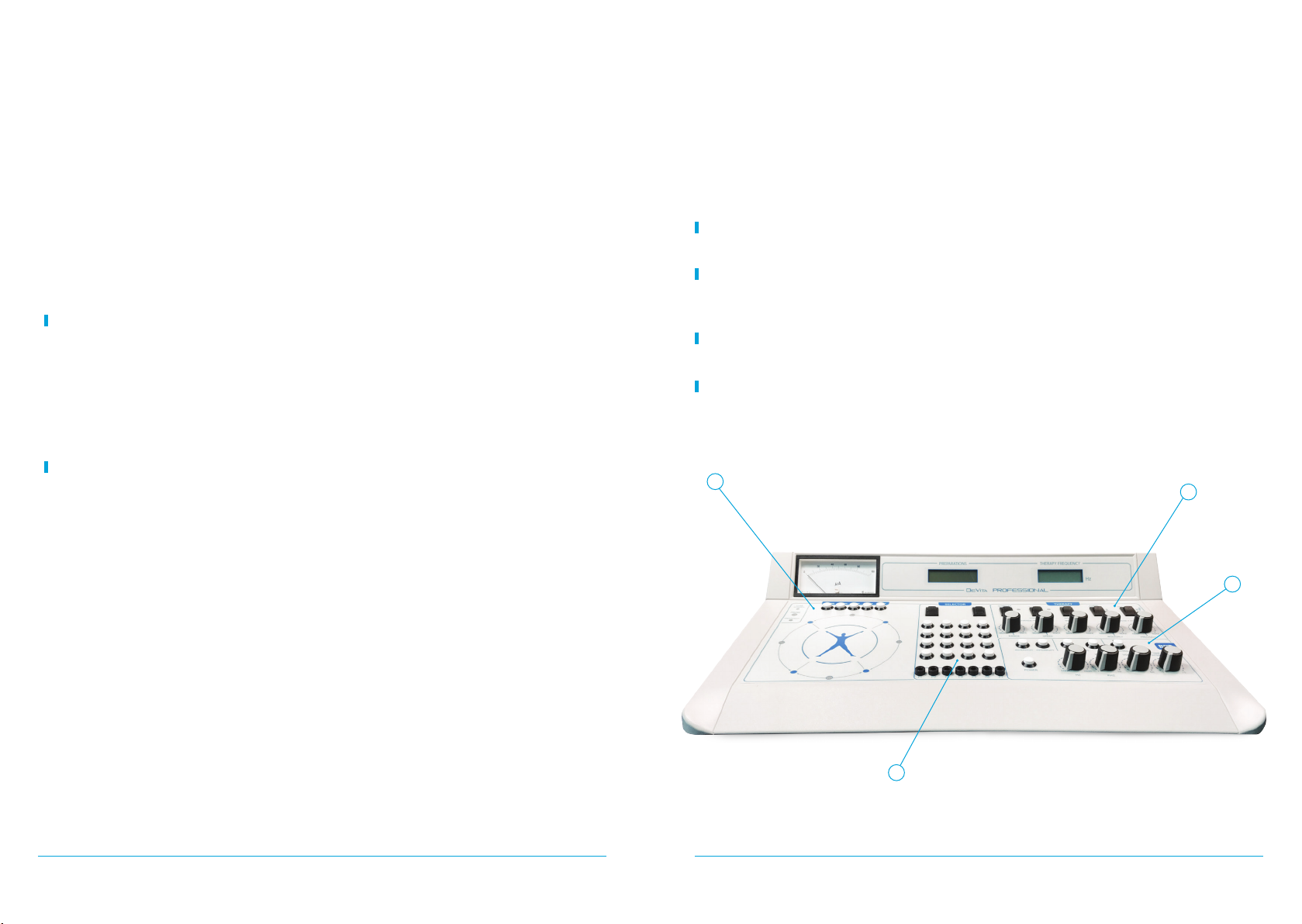
5. EXPLANATION OF THE BASIC MODULES OF THE PROFESSIONAL .....................................................................
Measuring Module ......................................................................................................................................................................
Electronic Selector Module ....................................................................................................................................................
Wellness Module –Therapy Unit .........................................................................................................................................
Wellness Module - Bioresonance Unit ...........................................................................................................................
6. MEASURE MODE – BASIC PRINCIPLES .................................................................................................................................
6.1. MEASURE ....................................................................................................................................................................................
Setting up the device for measure ....................................................................................................................................
VRT Testing Using the Electronic Selector (ES) .........................................................................................................
VRT testing using the resonator (honeycomb) with ampoules ......................................................................
6.2. ELECTRONIC SELECTOR (ES) .............................................................................................................................................
6.3. SETTING UP FOR BIORESONANCE MEASURES ......................................................................................................
Search Techniques and Electrical Parameter Measurement of Biological
Active Points (BAP) ......................................................................................................................................................................
6.4. DIRECT BIORESONANCE TESTING ...................................................................................................................................
Where in the body? What organ? .......................................................................................................................................
6.5. IS IT POSSIBLE TO TEST DIFFERENT THINGS AT THE SAME TIME? ..........................................................
6.6. USING COMPLEX FILTERS TO PRIORITIZE ...................................................................................................................
6
6
6
6
7
7
7
7
7
7
7
8
8
8
8
9
9
9
9
9
11
11
11
12
15
16
18
18
21
21
21
22
22
23
23
23
24
24
25
26
29
29
30
33
34
35
36
37
38
39
39
40
40
40
43
44
44
45
46
46
47
47
48
48
49
50

7
6
Note the meaning of below terms used in the manual:
THERAPY = HEALTH IMPROVEMENT and DIAGNOSTICS = PROGNOSIS OF HEALTH STATUS
Note the meaning of below terms used in the manual:
THERAPY = HEALTH IMPROVEMENT and DIAGNOSTICS = PROGNOSIS OF HEALTH STATUS
1. INTRODUCTION
on its circulation was expressed by ancient Esculapians of China, India, and Egypt. Every human
factors, modern life full of stresses, bad environment, its frequencies deviate from their natural
parameters, and a risk of reduction of body defences can occur.
its energy balance either in the whole or locally.
The most important advantage of DeVita Professional is the availability of device for measuring
the level of the body's condition and programs for health support by sessions. This allows you to
choose an individual prophylactic course for each person.
Wellness technique is a healthy diet, moderate physical exercises, fresh air, and cessation from
harmful habits - largely reduces the risk of various diseases. However, in today’s world it is not
always possible to commit oneself to the concept of wellness consistently. This is especially true
for large cities, with their constant stresses, rapid way of life and a poisoned environment.
DeVita-Professional devices are designed to help the body to maintain vitality at a high level, to
years to come.
2. SPECIFICATION
The measure mode
In the measure mode, measurements can be made according to the methods of Dr. Voll
and Dr. Schimmel. Parameters used are:
• Conductivity indicator ranges from 0 to 100
• Accuracy of measurement, ± 1%
• Voltage between the measure probe and hand electrode is 1.25 V
• Measure current is not greater than 12.5 mkA
• LED lights for «LOW POWER» and «VEGATEST» mode
• The Output signal can be of positive polarity, negative polarity, bipolar, bipolar inverse
• Pulse duration at level of 0.5 = 1 ms
• Range of pulse repetition rate, 0.1-99.99 Hz
• Maximum error of frequency setting, not more than ± 5%
• Output signal is a bipolar pulse bundle with a high frequency
• Range of pulse packet repetition rate, 0.1- 99.99 Hz
• Maximum frequency error of frequency setting, not more than ± 5%
Electronic selector (ES)
• 22800 digitized remedies of a wide variety of homeopathics
• A further 25200 empty memory slots to input your own remedies, foods and homeopathic
remedies
• The maximum number of remedies that can be given simultaneously to the visitor is 18
• Dynamic range, 0.1-99.99Hz
• Maximum error of frequency setting, not more than ± 5%
• Optic range, nm 468, 525, 590, 660, 880
Power
• AC adapter 220V/50Hz 12V/0.5A
• Current consumption, not more than, 0.33A
Operating conditions
• Ambient temperature from 10 to 35°C
• Relative humidity 80% at 25 °C
• PC connection assembly interface “BS-8”
• Average service life, not less than 5 years
• Weight: without accessories and spare parts 3 kg; as a whole unit 7 kg
Package Contents
1 x Device «DeVita Professional»
2 x Brass hand electrodes cylinders
2 x Brass foot electrode plates
1 x Universal measure probe

9
8
Note the meaning of below terms used in the manual:
THERAPY = HEALTH IMPROVEMENT and DIAGNOSTICS = PROGNOSIS OF HEALTH STATUS
Note the meaning of below terms used in the manual:
THERAPY = HEALTH IMPROVEMENT and DIAGNOSTICS = PROGNOSIS OF HEALTH STATUS
1 x Honeycomb cell for ampules
1 x Round metallic dish
1 x Beaker with lid
1 x Electrodes for recording on water
1 x External Antenna unit
1 x Computer interface «BS-8» with «EAVPRO 5.0» program
1 x Power supply unit
1 x Cables set
1 x Documentation set
3. RULES FOR USING THE DEVICE
Operating conditions
an antistatic mat and avoid carpet that tends to accumulate static charge. Shoes should be worn
as bare feet can also accumulate static charge. Wooden chairs are best, covered with cotton fabric,
not synthetic. High frequency electrical equipment should not be close by, not computers and radio
be kept to a minimum.
Safety measures
Do not connect the device to an AC adapter with a damaged power cord. Do not attempt to
repair the device yourself. If a fault occurs, please contact a service centre.
The device can be set up relatively easily by following these simple instructions:
1. Connect the AC adapter to the «12V» socket on the device (see Fig.3, number 2). The polarity
of the voltage does not matter.
2. Insert the AC adapter into a wall socket with 220V voltage.
3. Turn on the device with the «12V» switch. On the front of the device, the «PROB» LED should
illuminate.
unplug the AC adapter.
Warning: The «LOW POWER» LED indicates a reduced voltage power supply. In this case, the
exact correspondences of the technical parameters of the apparatus to the indicated standards
are not guaranteed.
OF THE PROFESSIONAL
The «DeVita Professional» device includes the following basic modules (Fig. 1).
– used for measuring the level of the body's condition according
to Dr. Voll and VRT testing according to Dr. Schimmel.
– contains 22, 800 digitized remedies of a wide variety
of homeopathics, as well as a further 25, 200 empty memory slots to input your own remedies,
foods and homeopathic remedies.
3-Wellness Unit – controls for using Electroacupuncture,
4-Wellness Unit
on the body. On the right side of the device are sockets to connect the individual modules
together (Fig. 2).
Fig. 1: External view of the DEVITA PROFESSIONAL
13
4
2

11
10
Note the meaning of below terms used in the manual:
THERAPY = HEALTH IMPROVEMENT and DIAGNOSTICS = PROGNOSIS OF HEALTH STATUS
Note the meaning of below terms used in the manual:
THERAPY = HEALTH IMPROVEMENT and DIAGNOSTICS = PROGNOSIS OF HEALTH STATUS
Socets (Fig. 2)
1 - «INPUT BRT» – Bioresonance Unit Input;
2 - «OUTPUT BRT» – Bioresonance Unit Output;
3 - «SEL» – Electronic Selector output;
4 - «ACTIVE» – active electrode Output.
Connected to the PROBE;
5 - «PASSIVE» – 1st passive electrode Outputs;
6 - «PASSIVE» – 2nd passive electrode Outputs;
7 - «PROBE» – universal Probe Input connection.
Key and Socets (Fig. 3)
1 - POWER ON/OFF «12V» Switch
2 - Power supply unit input «12V»
3 - QUANTUM light connector
5 - BS-8 interface block connector – for computer connection
Fig. 2: Right side view
1 2 3 4 5 6 7 8 9
10 11
Abduction or quadrant section
Output for quadrant leads;
9 - «RH» – «right hand»
Output for quadrant leads;
11 - «RF» – «right foot»
Output for quadrant leads.
43 5
Fig. 3: Rear view
1
2
6.1 MEASURE
Setting up the device for measure
In order to begin using the bioresonance measures using the Universal probe (we will refer to it
panel
(see Fig. 4, number 4).
In this case, the «PROB» LED illuminates green (Fig. 4, number 2).
Then on the «THERAPY» panel (Fig. 6), set the «THERAPY/DIAGNOSTICS» button to the
«DIAGNOSTICS» position.
to do the following:
1. Connect a wire from the «PASSIVE» socket (Fig. 2) to a brass hand electrode
2. Connect a short wire from the selector output «SEL» to the second socket «PASSIVE» (Fig. 2)
3. Insert the Measure probe (Fig. 5) into the socket «PROBE» (Fig. 2).
The DeVita Professional device allows for
measure according to the methods developed
by Dr. Voll and Dr. Schimmel. The «
panel to control the measure mode is shown
in Fig. 4.
There are three indicator LED lights on
GREEN in colour accept when in
Electroacupuncture mode when it will turn
POWER indicator if the correct voltage is
not being maintained. The second LED light
(no. 2) will be green when the PROBE button
is pressed on the panel. The third LED light
is the VEGATEST light which will be green
when the device is in the VRT MEASURE mode
(pressing the second button on the Measure
on the panel (see Fig. 6).
4 65 7 8
1
3
2

13
12
Note the meaning of below terms used in the manual:
THERAPY = HEALTH IMPROVEMENT and DIAGNOSTICS = PROGNOSIS OF HEALTH STATUS
Note the meaning of below terms used in the manual:
THERAPY = HEALTH IMPROVEMENT and DIAGNOSTICS = PROGNOSIS OF HEALTH STATUS
VRT Testing Using the Electronic Selector (ES)
Testing (VRT) according to Dr. Schimmel, the following set-up is required – see summary in
Diagram 1 below:
1 2
The protocols used for using bioresonance
measures and determining the deviations from
wellness standards are beyond the scope of this
manual. It will be taught in the intensive wellness
practicum that is an essential part of training to
use this sophisticated device. The manual is only
designed to help the practitioner set the device
up and it is good to really familiarize yourselves
with this.
Diagram 1: VRT Testing Using the Electronic Selector (ES)
1. Connect
HAND ELECTRODE
(brass cylinder)
to PASSIVE
connector
VOLL OR VRT MODE
CONNECTING THE ELECTRONIC SELECTOR
2. Connect SEL
to PASSIVE together
with short wire
3. Connect PROBE
to connector
The procedure is summarized in Diagram 2 below:
1. On the «THERAPY» panel, set the «THERAPY/DIAGNOSTICS» key to the «DIAGNOSTICS»
position (see Fig. 6).
2. On the « panel, press the «PROBE» button (see Fig. 4, number 4). In this case, the
«PROB» LED illuminates green.
3. For working with the Selector, it is necessary to connect a wire to the «PASSIVE» socket
(see Fig. 2), located on the right side of the device with the brass hand electrode.
4. Connect a short wire to the selector output «SEL» (see Fig. 2) and then to the second socket
«PASSIVE».
5. Insert the measure probe (Fig. 5) into the socket «PROBE» (Fig. 2).
For VRT testing, it is necessary to switch from Voll testing to the vegetative resonance «VRT»
test mode.
showing a low reading – usually around 20 – as it is in the Voll Testing Mode.
In order to begin testing in the VRT mode, it is necessary to place the probe on the point to
be measured, and then press and hold button «2» on the probe (see Fig. 5) for about 1 second,
Measure Mode- Press «PROBE»
LED turns green when the PROBE is pressed
Press to «DIAGNOSTICS»
MEASURES MODE

15
14
Note the meaning of below terms used in the manual:
THERAPY = HEALTH IMPROVEMENT and DIAGNOSTICS = PROGNOSIS OF HEALTH STATUS
Note the meaning of below terms used in the manual:
THERAPY = HEALTH IMPROVEMENT and DIAGNOSTICS = PROGNOSIS OF HEALTH STATUS
until the «VEGATEST» LED on the device illuminates. You will now be in the VRT testing mode,
and the indicator will automatically jump from the 20 in Voll Mode to 80 in the VRT mode. This is
summarized in Diagram 3.
Button «2» will not work if the probe is not on the point to be measured.
device will now transfer back to the Voll measure mode.
to MANUAL on the «THERAPY» panel. To switch the sound ON, switch to AUTO on the THERAPY
PANEL. This is summarized in Diagram 4.
Press the BUTTON 2 on PROBE for 2 seconds
to enter VRT Mode-VEGATEST. LED will show GREEN.
Press the BUTTON 2 again when exiting
the VRT Mobe and back to VOLL Mobe
2
Enable Sound-press
on «AUTO» SOUND CONTROL
FOR EFFECT
Mute Sound-press
on «MANUAL»
Diagram 4: Sound Control
VRT testing using the resonator (honeycomb)
with ampoules
1. On the measures panel, press the «PROBE» button (Fig. 4, number 4). In this case, the «PROB»
LED illuminates.
2. On the «THERAPY» panel, set the «THERAPY/DIAGNOSTICS» button to the «DIAGNOSTICS»
position (see Fig. 6).
3. Now connect a long wire from the «PASSIVE» socket (see Fig. 2) with the brass hand electrode.
4. Place the «resonator plate» (Fig. 7) on the table and connect this with a wire to the second
«PASSIVE» connector (see Fig. 2).
5. Insert the measure probe into the socket «PROBE».
6. To conduct a measure test, place the ampoule in the resonator plate. One can also test
allergies to allopathic drugs, cosmetics, jewelry, and other allergens by placing these on the
resonator plate, including food intolerances.
You are now ready for testing in the VRT mode – simply place the ampoules that you wish to
test on the resonator block and use VRT testing. This is summarized in Diagram 5 below.
If one does not want to use the digitized remedies in the
Selector, one has a choice to use their own external ampoules with
homeopathic remedies, foods and the like.
In order to set this up, we need to connect the metallic
honeycomb or «resonator plate»(Fig. 7) with the device. This is how
we do this:
Fig. 7: Honeycomb or
Diagram 5 - VRT Testing Using the Resonator
WORKING & TESTING WITH AMPOULES
2. Connect the Resonator
or Honeycmb on the second
PASSIVE connector
1. Connect HAND ELECTRODE (brass cylinder)
3. Connect PROBE
to connector
VRT TESTING MODE
SOUND CONTROL
RESONATOR TESTING

17
16
Note the meaning of below terms used in the manual:
THERAPY = HEALTH IMPROVEMENT and DIAGNOSTICS = PROGNOSIS OF HEALTH STATUS
Note the meaning of below terms used in the manual:
THERAPY = HEALTH IMPROVEMENT and DIAGNOSTICS = PROGNOSIS OF HEALTH STATUS
Once the code number corresponding to the remedy is entered and the Star key (*) is pressed,
the selector will show the name of the remedy on the screen of the Professional. The remedy is
now stored in memory and ready to be administered.
In order to begin to administer this remedy to the visitor, the «OUT» button must be pressed.
Immediately on the screen a message will be displayed.
e.g. «Substance issued: N».
N - Indicates the number of remedies being administered concomitantly.
To stop administering the remedies you have to press the «OUT» key again.
that will be administered together with the previous one, you need to press the UP arrow to move
to another level – this will be indicated on the screen as numbers 1, 2, 3 and so on up to level 18.
When you change levels with the UP arrow, then it is a simple case of entering the code number
for the next remedy that you wish to use.
As mentioned above, it is possible to administer up to 18 remedies simultaneously. These can
be seen on the screen by scrolling using the UP and DOWN arrows on the Selector.
If you wish to erase a remedy from the list, then you simply enter the number zero - «0» - and
it will be erased.
ELECTRONIC SELECTOR
6.2 ELECTRONIC SELECTOR (ES)
On the «PREPARATIONS» display, the message:
remedy you wish to use, taken from the remedy manuals provided. Press « ». When you enter a
wrong number, amend it by pressing the « » key.
remedy, you are interested in administering. These are found in the number of remedy manuals
containing all the homeopathic and homotoxicology remedies from companies such as Heel,
Pascoe, Waleda, Regweg and more.
«POWER»
«LIGHT»
• The ELECTRONIC Selector has 18 LEVELS or FILTERS
• Use SCROLL buttons
• Use number «0» to delete input
The Electronic Selector enables one to access the 22, 000 or so
digitized remedies or ampoules stored in the memory banks of the
DeVita Professional. It enables the practitioner to access any of these
remedies in order to copy onto sugar pills as homeopathics that
can be given to the visitor, or as a direct remedy that can be given
The appearance of the module of the electronic selector is shown
in Fig. 8.
Switch on the selector with the «POWER» button. Connect «SEL»
socket and «PASSIVE» socket with a short cable (Fig. 2).
If necessary, turn on the back light indicator with the «LIGHT» key. Fig. 8: ES
«ES» PANEL
Diagram 7: Electronic Selector
The displey «PREPARATIONS» should appear as:
If you enter the wrong number, press
equivalent to ENTER. To begin
broadcastingn press OUT - selector
will display «Provide substance: N»
designation numbers.

19
18
Note the meaning of below terms used in the manual:
THERAPY = HEALTH IMPROVEMENT and DIAGNOSTICS = PROGNOSIS OF HEALTH STATUS
Note the meaning of below terms used in the manual:
THERAPY = HEALTH IMPROVEMENT and DIAGNOSTICS = PROGNOSIS OF HEALTH STATUS
6.3 SETTING UP FOR BIORESONANCE MEASURES
Before you begin bioresonance testing, you need to set up the Professional device as follows:
Connect a short length of wire on the side of the device from the SEL connector to the PASSIVE
connector – you can use any of the two passive connectors, it does not matter as they are the
same (see Fig. 2).
Connect the hand electrode to a long wire from the remaining PASSIVE connector.
Press the PROBE button (see Fig. 4).
On the SELECTOR section of the device, press POWER and LIGHT
On the «THERAPY» panel of the device, where we see the THERAPY/DIAGNOSTICS switch, place
this on the DIAGNOSTICS section.
You are now ready for bioresonance testing.
In order to be successful in bioresonance testing using the Probe, it is important to identify the
conductivity indicator should show the same. This is the energetic point that interests us.
On a technical level, there are two points to bear in mind:
• We need to get the indicator correct by applying the correct pressure - this is known as
«opening» the point or energizing the point.
• Then we can ask the question and get the answer through the indicator.
It is known as bioresonance as we use a voltage input into
the energetic point (Voltage between the measure probe and
hand electrode is 1.25 V, current is not greater than 12.5 mkA).
If the energetic signature is the same as there is no
resonance, then there will not be an indicator drop. However, if
there is resonance then there will be a stress on the Autonomic
Nervous System and we will witness an indicator drop.
It is similar to the tuning fork phenomenon.
pressure of about 100 – 150 grams.
reliable reading.
We need to use the lightest pressure that gives us the best reading. Using too much pressure
will result in «killing» the point and then we would need to calibrate with another point.
Always wet the probe point with a moistened cotton wool swab or use the swab directly on the
a 0.1% saline solution to moisten the cotton wool ball.
If the indicator on the Voll setting (not VRT setting) gives us a reading above 20 unit then this
minimal movement of the skin so will not interfere with our readings.
At the point where you place the measure probe, there will be a little hollow like a little «hole».
This takes a little practice to master but persistence and patience is what is required to master this
crucially important technique.
the pressure of your measure probe – it should not be more than 100 – 150 g.
On the second time we can release the pressure to make certain that there is an indicator
The more one practices, the better the measurement will become as our muscles get trained
to use the same pressure consistently.
When you have found the point on the Voll testing mode and the reading is above 20 unit, then
to enter the VRT mode, the indicator should automatically go to 80 (see Fig. 5, button 2).
Fig. 9

21
20
Note the meaning of below terms used in the manual:
THERAPY = HEALTH IMPROVEMENT and DIAGNOSTICS = PROGNOSIS OF HEALTH STATUS
Note the meaning of below terms used in the manual:
THERAPY = HEALTH IMPROVEMENT and DIAGNOSTICS = PROGNOSIS OF HEALTH STATUS
Try practicing holding the probe steadily with even pressure on the point in VRT mode and keep
the indicator steady at 80 unit for 5 – 6 seconds.
One way of testing whether the point is valid is to place a MALAISE CONTROL in the visitor’s
other hand or on the honeycomb. The Disorder Control ampoule can be a poison such as a
pesticide that will almost always stress the ANS and result in an indicator drop. An indicator drop
while using a Disorder control is a POSITIVE and valid indication that the point we are reading from
is good. Another disorder control that can be used is Cuprum Metalicum which is in the Selector
(3032*1).
If the indicator responds within 3 seconds, then this is all the time required – within this 3
seconds there will either be an indicator drop or not. It is not good practice to keep the measure
may act as a stressor for another visitor resulting in an indicator drop before the testing has even
began. This is why it is imperative to clean the hand electrode with some alcohol and wipe the
probe with a little cotton wool with alcohol.
The Professional also has a sound or tone connected to the probe and it is good to have this
tone and hue of the sound.
remain at the same level no matter how much pressure you are applying to the skin.
The optimum pressure of the «active» electrode probe on the BAP is a value that lies within the
following limits:
• for an electrode of 2 mm diameter – 50 - 100 gram force
• for an electrode of 3 mm diameter – 60 - 110 gram force
• for an electrode of 4 mm diameter – 70 - 200 gram force
The electrode we use on the Professional is usually 3 mm.
Moving to the «measurement plateau» takes place smoothly over 2-3 seconds, without jerking
of the «active» electrode probe which could result in damage to the epidermis of the skin in the
area of the BAP projection.
The skill of achieving the optimum pressure on the BAP and reaching the «measurement
plateau» can only be acquired with practice and more practice – this is usually the hardest part of
the learning process for most students and some even give up before they have mastered this.
It is a little like playing a musical instrument, it requires practice, discipline and determination, as
well as time in order to improve and reach a satisfactory level. All students should be encouraged
to persist as the rewards are great.
There are not many competent bioresonance measureians and they are in high demand for
determining the causative factors behind many disease processes.
6.4 DIRECT BIORESONANCE TESTING
When testing for one item only, this is known as a DIRECT test which is done at the FIRST
There are a number of questions we can ask?
Where in the body? What organ?
During the direct testing, we place the organ in question, e.g. the liver, in the circuit using the
Selector – if there is an indicator drop then this is an indication that there is a problem with the liver.
This is telling us WHERE in the body is the problem area.
liver. This is FILTER TESTING at level 2, so we are now moving away from the direct testing as
the like. If the indicator drop continues, then it means that there is no relationship between the
microorganism tested and the liver. However, if the indicator remains STABLE without dropping,
the functioning of the liver.
Let’s look at another example, using the prostate:
E.g. PROSTATITIS – put in prostates ampoule and this will tell us that there is a problem with the
prostate. Will get an indicator drop (ID).

23
22
Note the meaning of below terms used in the manual:
THERAPY = HEALTH IMPROVEMENT and DIAGNOSTICS = PROGNOSIS OF HEALTH STATUS
Note the meaning of below terms used in the manual:
THERAPY = HEALTH IMPROVEMENT and DIAGNOSTICS = PROGNOSIS OF HEALTH STATUS
80, then on the second and third there will be a sharp drop. This is a POSITIVE response, meaning
If we now want to see if the prostatitis is related to Chlamydia, for example, we keep the
prostatitis code in level 1 and place the Chlamydia in level 2 – when we now test using VRT we
would expect the opposite indicator reaction if the test is positive and there is indeed a relationship.
This means that if there is a relationship, there will NOT be an indicator drop. If the indicator drop
continues with the Chlamydia in circuit, it means that there is no relationship.
have a valid point.
for CUPRUM METALICUM – 3032*1 – this is the equivalent of the DISORDER CONTROL in other
methods of testing such as VEGA testing.
If there is a drop in the indicator, then this suggests that the point is valid. If there is not a drop
in the indicator, then this means that this point is not valid and will not give us a correct reading.
The Cuprum metallicum will stress the Autonomic Nervous System and this will result in an
indicator drop. One can also use any other toxins or poisons that will also stress the ANS such as
other heavy metals, as well as a pesticide or insecticide in a small ampoule in the honeycomb.
may be due to a number of factors:
way.
2. Could have Reynould’s Syndrome.
6.5 IS IT POSSIBLE TO TEST DIFFERENT THINGS AT THE SAME TIME?
to combine various things that may belong to the same family. For example let us say we
For example, we may place these two:
LEVEL 2 - 3008*4 – Trace minerals
If we then press OUT and test these two together, if there is no indicator drop, then there are no
go back and erase one and only test against one, and vice versa in order to determine which one
family, or the dairy family, or the nightshade family and so on – if there is no drop then they are not
intolerant to this food family. If there is a drop, then one would need to test each individual food in
this family individually.
6.6 USING COMPLEX FILTERS TO PRIORITIZE
We can use these algorithms or codes to decide which quadrant of the body is the most
These codes are:
LEVEL 1 - 3032*1 – Cu met D400
LEVEL 2 - 3008*1 – Zn met D26
LEVEL 3 - 3012*7 – Ferr met D26
LEVEL 4 - 3012*5 – Manganum met D26
are placed together and so you are really working on LEVEL 1.
6.7 CONTRAINDICATIONS TO USING VRT MEASURES
As VRT Measure uses electricity – a small voltage of 1.25V is used at the end of the Probe -
if there are circulatory disturbances in peripheral circulation then it is possible that a thrombosis
can occur.

25
24
Note the meaning of below terms used in the manual:
THERAPY = HEALTH IMPROVEMENT and DIAGNOSTICS = PROGNOSIS OF HEALTH STATUS
Note the meaning of below terms used in the manual:
THERAPY = HEALTH IMPROVEMENT and DIAGNOSTICS = PROGNOSIS OF HEALTH STATUS
Contraindications to the use of VRT Measure therefore include:
• benign and malignant tumours
• hereditary hemorrhagic anaemia
• bleeding disorders
• purpurae and other hemorrhagic conditions;
• pregnancy
• acute infections and fever conditions of unknown origin
• chronic infectious diseases in acute stages (tuberculosis, brucellosis, etc.)
• heart disease, lungs and other internal organs
• active rheumatism
• myocardial infarction in the last two months
• venous thrombosis and embolism in the acute period
• sudden emaciation
• congenital malformations of the central nervous system
• the presence of implanted pacemakers in the visitor
• individual intolerance to electric current
• injuries and diseases of the skin in the location of electrical stimulation
• acute pain syndromes of unknown origin
• condition of acute psychological stimulation or intoxication.
points as well as auricular acupuncture points.
6.8 QUADRANT TESTING
Quadrant testing enables the practitioner to quickly identify general problem areas of the
Setting up for quadrant testing
In the measures mode according to Dr Voll, the device allows a measurement using the
quadrant leads (see Fig 2). Connect the leads to the Abduction or Quadrant Section (nos. 8 – 11). To
brass hand-connectors to no 9 connector). These connectors are located on the right side of the
device (Fig. 2). See summary in Diagram 8 below.
plates to no 11).
On the «THERAPY» panel of the device (Fig. 1, section 3) set the THERAPY/DIAGNOSTICS switch
to the «DIAGNOSTICS» position.
Conducting quadrant testing
With the THERAPY/DIAGNOSTICS switch on DIAGNOSTICS, and the visitor holding the two
brass hand electrodes, and feet on the two foot electrodes, carry out the Quadrant measurements
as follows (see Fig. 4 to identify the buttons below):
1. Press button 5 (LH/RH) to begin measuring the «LH-RH» – note the indicator reading (Fig. 4)
2. Press button 6 (LF/RF) to begin measuring the «LF-RF» – note the indicator reading (Fig. 4)
3. Press button 7 (LH/LF) to begin measuring the «LH-LF» – note the indicator reading (Fig. 4)
4. Press button 8 (RH/RF) to begin measuring the «RH-RF» – note the indicator reading (Fig. 4).
Make notes of the measurements for each of the 4 quadrants as this is important for the
interpretation.
Set MODE switch to «DIAGNOSTICS»
Measurements are performed in the following sequence:
1.LH-RH
2. LF-RF
3. LH-LF
4. RH-RF
Fig. 10: Connection Diagram for Quadrant Testing
QUADRANT TESTING

27
26
Note the meaning of below terms used in the manual:
THERAPY = HEALTH IMPROVEMENT and DIAGNOSTICS = PROGNOSIS OF HEALTH STATUS
Note the meaning of below terms used in the manual:
THERAPY = HEALTH IMPROVEMENT and DIAGNOSTICS = PROGNOSIS OF HEALTH STATUS
Interpreting the quadrant testing results
degeneration in organs found in the 4 quadrants. The 4 quadrants relate to organs or physiological
systems, as shown in the Diagram 9 below.
QUADRANT RELATIONSHIP
NO. MEASUREMENT SEQUENCE RELATIONSHIP WITH ORGANS & TISSUES
1RH - LH
(+) (-)
Heard, Lungs, Esophagus,
Cervical-Thoracic Spine
2RF - LF
(+) (-)
Uroganital organs, Rectum,
Lumbosacral Spine
3LH - LF
(+) (-)
and Transverse Colon, Spleen, Pancreas,
Kidney and Uroganital organs
4RH - RF
(+) (-)
AscendingColon, Appendix, Kidney and
Uroganital organs
Illustrated below in Diagram 10 is a typical example of the use of quadrant diagnosis based on
between the lowest and highest numbers of any of the 4 measures or quadrants to identify
pathology. This will become clearer as we study the numbers on Diagram 10 below.
in the 4 quadrants of more than 6 units or points on the indicator. The F-F electrode is indicating 95,
The fact that 95 is a higher number than the other measurements of 82 is indicating
INFLAMMATION. If this number was lower than 82 by at least 6 points, then this would be an
indication of DEGENERATION. We are always looking to compare the highest and lowest numbers
organ in this quadrant, in this case the prostate, it is necessary to use VRT bioresonance testing,
the prostate, or prostatitis.
AN EXAMPLE OF INFLAMMATION AN EXAMPLE OF INFLAMMATION
QUADRANT MEASUREMENT RESULTS
h-h
82
95
f-f
h-f (l)
82
h-f (r)
82
95
f-f
h-h
82
h-f (l)
82
h-f (r)
82
Chromic appendicitis or right-side adnexitisAdnexiti (prostatits)
PRELIMINARY CONDITION PRELIMINARY CONDITION

29
28
Note the meaning of below terms used in the manual:
THERAPY = HEALTH IMPROVEMENT and DIAGNOSTICS = PROGNOSIS OF HEALTH STATUS
Note the meaning of below terms used in the manual:
THERAPY = HEALTH IMPROVEMENT and DIAGNOSTICS = PROGNOSIS OF HEALTH STATUS
QUADRANT MEASUREMENT RESULTS
Again to reiterate, if the measure in one quadrant is HIGHER than the other quadrants, then
this would be an indication of INFLAMMATION of the organ systems in that particular quadrant.
If the quadrant measure is LOWER than the other quadrant readings, then this is an indication
of DEGENERATION.
The Quadrant measurements is a good way to quickly determine where
there may be pathologies or imbalances in the body – it is more a qualitative measure than
a quantitative one as it points to WHERE in the body the problem may be, not WHICH particular
7.1 BIORESONANCE (BRT) EFFECT MODE
of the body. No external energy (low-frequency, ultrasonic, etc.) is produced by the device itself as
itself.
a second electrode, the harmonious frequencies being positively fed back (positive feedback)
whilst the disharmonious frequencies are negatively fed back, i.e. inverted (negative feedback).
AN EXAMPLE OF INFLAMMATION
h-h
82
68
f-f
h-f (l)
82
h-f (r)
82
Degenerative process
of pelvic organs
PRELIMINARY CONDITION
One can examine the various organs in the lower quadrants using VRT testing using the
following algorithms:
FEMALE
Ovaries – 4047*6
Vagina – 3026*1
Uterus – 4048*1
Cervix – 785*1
Endometrium – 792*1
Fallopian tubes – 823*1
Female urethra – 826*1
MALE
Testes – 3020*6
Seminiferous tubules – 786*1
Right epididymis – 793*1
Seminal vescicles – 3020*7
Vas deferens – 791*1
Prostate – 3021*3
Penis – 805*1
Urethra – 827*1
GENERAL
Kidney – 3018*3
Bladder – 3021*4
Lumbar vertebrae – 3022*4
Sacral vertebrae – 3022*5
Examining the same diagram again, but comparing the top diagram with the bottom, even
Let us now examine another example where this time the problem is one of degeneration as
The fact that the F-F measure is lower means that we are looking at a DEGENERATIVE picture
of the organs represented in that particular quadrant.

31
30
Note the meaning of below terms used in the manual:
THERAPY = HEALTH IMPROVEMENT and DIAGNOSTICS = PROGNOSIS OF HEALTH STATUS
Note the meaning of below terms used in the manual:
THERAPY = HEALTH IMPROVEMENT and DIAGNOSTICS = PROGNOSIS OF HEALTH STATUS
Let us say, for example, that we get the following readings:
LH = 80
RH = 50
RF = 60
LF = 95
We then proceed to treat each pair separately, moving clockwise around the circle. The INPUT
BRT is always held in the LOWEST reading of the pair being treated, whereas the OUTPUT BRT is
always held in the hand or foot with the HIGHEST reading. This is because the energy will travel
from the OUTPUT BRT electrode through the strongest pair and then to the weaker quadrant of
the body that requires strengthening.
To summarize:
OUTPUT ELECTRODE = HIGHEST READING
INPUT ELECTRODE = LOWEST READING
physiological endogenous regulatory forces can regulate the biological processes unhindered.
traditional methods, or involves a lot of time or expense.
Above all, BRT helps with weakening of the immune system, allergies, pain of all types and so on.
treat the visitor with the same hand and foot electrodes – this is considered a BASIC BRT
EFFECT that will help the visitor to remove any energetic blockages, therefore facilitating their
healing process, as well as inverting and neutralizing any pathological frequencies from the visitor
possible to use the hand electrodes for problem areas above the waist, and the foot electrodes for
In order to use the device for BASIC BRT EFFECT, the following must be set-up:
1. Connect the hand electrodes to INPUT BRT and OUTPUT BRT.
2. Using the BRT control panel (Fig 11) – turn POWER button ON.
3. Set the VOLUME knob to 7 – at this setting the signal intensity being picked up by the visitor is
time between each signal. As we increase the TIME OF INTERRUPT we also increase the pause
time between the signals, while the signal intensity decreases. As we decrease the TIME OF
INTERRUPT, we reduce the pause time and increase the signal intensity. For adults (18 years plus),
we set it to 7 and for children (less than 18 years), we set it to 3.5.
In order to determine which electrodes are held where, we need to use VRT testing on each of
the thumbs and large toes – see Diagram 12 below.
Diagram 12: VRT Testing
III
I
Input
Output
Output
Input
80
95
50
60
II
IV
Input Input
LH
LF
RH
RF
BIORESONANCE VRT TESTING
Output Output

33
32
Note the meaning of below terms used in the manual:
THERAPY = HEALTH IMPROVEMENT and DIAGNOSTICS = PROGNOSIS OF HEALTH STATUS
Note the meaning of below terms used in the manual:
THERAPY = HEALTH IMPROVEMENT and DIAGNOSTICS = PROGNOSIS OF HEALTH STATUS
A powerful feature of the Professional is the ability to invert pathological frequencies related to
allergens and therefore neutralize these so that they no longer create symptoms.
This is summarized in diagram 14 below.
Connect the Resonator plate or pot using a short wire to the INPUT BRT of the Professional. To
the other end of the round container connect another long wire and to the end of this a brass hand
electrode. To this round container will be added the ALLERGEN such as pollen, or dust, or food etc.
To the other resonator plate or pot connect a long wire and attach another hand electrode to the
end of this. This will go to the OUTPUT BRT connector on the side of the Professional.
• Press INVERSION ON.
• Press INTERRUPT button to OFF.
• The TIME OF INTERRUPT button is not needed when the INTERRUPT button is OFF.
• Set the VOLUME control to 60.
• FILTER is OFF.
joins lines – at the centre of this – this is right in the middle of the thumb. Measure each thumb
of each hand – the hand that has the highest reading will hold the INPUT electrode containing the
ALLERGEN. In the other hand, hold the OUTPUT electrode.
This allergen desensitization program should be repeated 4 times for best results – this can
be done over 4 consecutive days or longer with intervals in between. Drink plenty of water during
the desensitization.
(50) – as the LH has the highest reading, we place the hand electrode from the INPUT BRT into the
Then we will then move clockwise around the quadrant, treating the RH (50) and the RF (60). As
the RF is the highest reading in this pair, we remove the hand electrode and replace it with the foot
electrode from the OUTPUT BRT connector, which the Right Foot will rest on, while the Right Hand
We basically do the same for the RH – LF and LF – LH pairs, using the same principles as
mentioned above.
If two pairs are of equal measurement, say the RH is 50 and the LH is 50, then we will initially
use the INPUT BRT electrode in the right hand for 5 minutes, with the OUTPUT BRT in the other
a further 5 minutes.
The complete BASIC BRT EFFECT should be completed in less than 25 minutes.
«THERAPY» panel, set the «THERAPY\DIAGNOSTICS» key to the «DIAGNOSTICS» position
(see Fig. 6).
Switch on BRT mode with the «POWER» button on the «BRT» panel (see Fig. 11) or button «1»
on the Measure probe.
The setup is summarized in Diagram 13 below.
1. FILTERS & CONTROL - OFF
2. INVERSION & INTERRUPT - IN
3. VOLUME - Max (60)
4. TIME OF INTERRUPT - Set to 3.5 for children
or 7 for adults
BRT MODE BRT AGAINST ALLERGIES
EXEMPLE: How to get rid of allergy to olive pollen?
1. Connect resonator and hand electrode to OUTPUT BRT - water / alcohol
2. Connect the honeycomb or resonator and hand electrode with the INPUT BRT
connector - olive pollen
INTERRUPT = OFF
INVERSION = ON
INTERRUPT = ON
VOLUME = 7 or 3.5
FILTER = OFF
1
52
6
5. INPUP BRT - Hand or Foot electrode
6. OUTPUT BRT - Hand or Foot electrode
7. Press POWER - To enable BRT

35
34
Note the meaning of below terms used in the manual:
THERAPY = HEALTH IMPROVEMENT and DIAGNOSTICS = PROGNOSIS OF HEALTH STATUS
Note the meaning of below terms used in the manual:
THERAPY = HEALTH IMPROVEMENT and DIAGNOSTICS = PROGNOSIS OF HEALTH STATUS
Wellness with , autonosodes and ES
, faeces, nails and skin which
all carry pathological frequencies and invert these to help neutralize them and therefore alleviate
Drainage, and other homeopathics from the Electronic Selector. See Diagram 15 below for a
summary:
which would normally take about 20 minutes with the VOLUME set to 7. This means that the
the body secretions themselves.
In this case, when the BRT treatment is complete, we can turn the VOLUME up to 60 and run the
programme for 5-7 minutes to complete the autonosode. This homeopathic is given to maintain
EXEMPLE: SALIVA, BLOOD, MUCUS, URINE, FAECES, SKIN, NAILS
2. Connect resonator and hand electrode to OUTPUT BRT connector - water/alcohol
1 2
INVERSION = ON
INTERRUPT = OFF
VOLUME = 60
LOW FILTER = ON
with VOLL testing)
using the Antenna, while concomitantly feeding in remedies and detox programmes from the
Electronic Selector (ES).
See the set up in the diagram below – the short wire connects between the INPUT BRT and the
SEL, while the OUTPUT POT connects to the OUTPUT BRT connector and the hand electrode plugs
directly into the OUTPUT POT - summary in Diagram 16 below.
WELLNESS WITH AUTONOZODES & ES
EXEMPLE: SALIVA, BLOOD, MUCUS, URINE, FAECES, SKIN, NAILS
2. Connect resonator and hand electrode to OUTPUT BRT connector - water/alcohol
1 2
• INVERSION = ON
• INTERRUPT = OFF
• VOLUME = 60
• LOW settowith VOLL testing)
OUTPUT: Water/Alcohol
TIME to COMPLETION: 5-7 min
Diagram 15-b: Autonosodes and ES
1. Short wire frome INPUT BRT to the SEL connector
2. Connect resonator and hand electrode to OUTPUT BRT connector - water/alcohol
1
2
INVERSION = ON
INTERRUPT = OFF
VOLUME = 60
LOW FILTER = ON
settowith VOLL testing)
ES: DRAINAGE, DETOX, MESENCHYME
Diagram 16: Autonosodes and ES
WELLNESS ALLERGIES WITH BRT
AUTONOZODES & ES
EXEMPLE: SALIVA, BLOOD, MUCUS, URINE, FAECES, SKIN, NAILS
3

37
36
Note the meaning of below terms used in the manual:
THERAPY = HEALTH IMPROVEMENT and DIAGNOSTICS = PROGNOSIS OF HEALTH STATUS
Note the meaning of below terms used in the manual:
THERAPY = HEALTH IMPROVEMENT and DIAGNOSTICS = PROGNOSIS OF HEALTH STATUS
out LOW or HIGH signals – this may be required by the experienced specialist who is absolutely
certain about in the degree of disability the person.
degree of disability the person.
through – this one would want to do if the disease process being treated was ACUTE.
other frequencies through – this one would want to do if the disease process being treated was
CHRONIC.
below this is made clearer.
Looking at Diagram 17, if we determine that one of the organs we are testing, say prostate is
st 100 Hz
range as the potency D3 is higher than 100 Hz. This will allow frequencies between 101 and 1,000
Hz to penetrate, but cut out the frequencies below 100 Hz.
1 2 3 4 5 6 7 8 9 1022 3 4 5 6 7 8 9 1032 3 4 5 6 7 8 9 1042 3 4 5 6 7 8 9 105
panel is needed.
1. Switch on BRT mode with the «POWER» button on the «BRT» panel (see Fig. 11). In this case,
the corresponding LED illuminates.
2. Set «VOLUME» to 60 units.
3. Switch on the «Control» mode with the «CONTROL» button. In this case, the corresponding
LED illuminates and an audible signal sounds.
4. Switch on the «Inversion» mode with the «INVERSION» button. The sound will stop, signaling
pathological information suppression mode. Switch on the «inversion» mode with the «INVERSION»
button again.
7. Switch on the «Interrupt» mode with the «INTERRUPT» button. Set the «TIME OF INTERRUPT»
knob to position «1». There should be a long beep and a short pause. At position «15» there should
This is the end of the testing routine – this does not necessarily have to be repeated every time
the specialist uses BRT – perhaps it is good to run this checking routine every day when BRT is
began with visitors.
CHOOSING FILTERS BASED ON POTENCIES

39
38
Note the meaning of below terms used in the manual:
THERAPY = HEALTH IMPROVEMENT and DIAGNOSTICS = PROGNOSIS OF HEALTH STATUS
Note the meaning of below terms used in the manual:
THERAPY = HEALTH IMPROVEMENT and DIAGNOSTICS = PROGNOSIS OF HEALTH STATUS
7.2 ELECTROACUPUNCTURE EFFECT MODE
acupuncture and the Voll acupoints. These are the points where treatment is conducted using the
Probe – there is also a small probe provided for this type of work in the Professional.
The ACTIVE connector is the POSITIVE (+ve) and the PASSIVE connector is the NEGATIVE (-ve).
To set up the Professional for Electroacupuncture, do the following:
electrode on the PASSIVE connector (-ve). One can also use the MEASURE PROBE (Fig. 5) in the
PROBE connector as the –ve.
2. Set the INTENSITY knob to MIN position. This is important; as if the INTENSITY is on high and
the visitor picks up the hand electrodes they will be given a sudden shock which is harmless but
unpleasant!
3. Press THERAPY on the «THERAPY» unit (Diagram 18)
4. Set the FREQUENCY using the ROUGHLY and PRECISELY knobs. You will see the frequency
in hertz on the screen «THERAPY FREQUENCY».
5. Set to MANUAL mode.
6. Set the polarity of the pulses with «FORM IMPULSE» and «POLARITY» buttons. With the
FORM IMPULSE we can choose the form of the wave we want to use. If we need to ADD energy or
«Qi» to the acupuncture meridians, as in cases of DEGENERATION – we use the –ve polarity button
then the button is DOWN. In the UP position energy will be given to the acupoint for cases of
degenerative processes.
8. When the button is DOWN on the Sinusidal wave, we use this setting when there is no
degenerative process but the problem is more functional. See Diagram 18 for a summary of
settings.
2. FORM IMPULS & POLARITY
1.
AUTO
MANUAL
corresponds to «Wave swing»
(0.1 - 99,99 Hz)
corresponds to Setting
(0.1 - 99,99 Hz)
7.3 ELECTROMAGNETIC EFFECT MODE
in AUTO MODE where the device will set itself to wobble between 0.1 – 99,99 Hz and back again
AUTOMATICALLY – the only thing that can be changed here is only the wobble speed.
The other mode is the MANUAL MODE where one can either set the FIXED frequency and the
device will run only at this frequency MANUAL MODE, or one can set a range of frequencies and
wobble between them (MANUAL MODE WITH SWING).
Let us examine how to set up all these three modes:
Auto mode
1. Set the «THERAPY/DIAGNOSTICS» switch to the «THERAPY» position (Fig. 6).
2. Connect the Antenna to the «ANTENNA» socket on the back of the device (Fig. 3, number 4).
3. Set the «MANUAL» mode of the device with the «AUTO/MANUAL» key set to the «AUTO»
mode: this corresponds to the automatic adjustment of the frequency range from 0.1 to 99,99 Hz.
4. Set the «RANGE» knob to MIN
5. One can change the wobble speed with the «SPEED» knob – for children about ¼ turn and
adults ½ turn - SPEED – for children this should be set to 1 minute and adults 3 minutes.
LCD display shows the exposure frequency.
These instructions are summarized in Diagram 19 below.
Place on THERAPY
Place on AUTO MODE
RANGE button on MIN
SPEED botton Settings:
¼ setting for CHILDREN
½ setting for ADULTS INTENSITY
FREQUENCY dose not
work in AUTO mode
Connect Antena
for Electromagnetic
Therapy (EMT)
Table of contents
Other Deta-Elis Measuring Instrument manuals