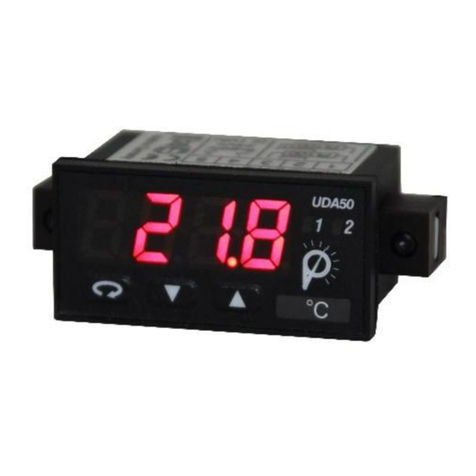
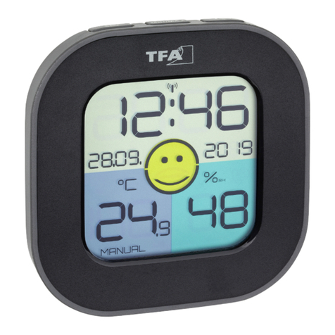
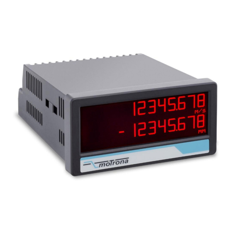
promesstec UDA 50-A Series User manual

user manual UDA 50-…-A & -B
UDA 50-…B… from page 2
UDA 50-…A… from page 15

Technical features:
•red display of -1999…9999 digits (optional: green, orange or blue)
•minimal installation depth: 27 mm without plug-in terminal
•Display adjustment via factory settings or directly at the sensor signal possible
•Min/Max-memory
•10 adjustable supporting points
•display flashing at treshold exceedance / undershooting
•tara-function
•programming lock via code entry
•protection class IP65 at the front
•Plug-in screw terminal
•accessories: pc-based configuration software PM-TOOL with CD and USB-adapter for displays
without keyboard and for easy parameterisation of standard devices
user manual UDA 50-…-B-0
Direct current / Direct voltage signals 0-20 mA, 4-20 mA, 0-10 VDC
UDA 50 version 2.1.1
promesstec GmbH
Niedersachsenstraße 4
D –48465 Schüttorf
Fon: +49 (0)25923 / 90229-0
Fax: +49 (0)25923 / 90229-29
www.promesstec.com

Identification
STANDARD-TYPE ORDER NUMER
Direct voltage / Direct current
Housing dimension:
48x24 mm
Articel-no. 99-000949
UDA 50-2-B-0
Articel-no. 99-001711
UDA 50-3-B-0
Dimension symbols are to specified when ordering, e.g. mbar

Content
1
1. Short description 2
2. Assembly 2
3. Electrical connection and connection examples 3
4. Function description and operation 4
4.1. Programming software PM-TOOL 4
5. Setting the display 5
5.1. Switching on 5
5.2. Standard parameterisation (flat operating level) 5
Value assignment to control the signal input
5.3. Programming lock RUN 6
Activation / Deactivation of the programming interlock or change into extended
parameterisation
5.4. Extended parameterisation 6
Superior device functions like e.g.:
- rescaling of the input signals, EndA, OFFA 6
- parameterisation of the TARA-function, TARA 6
- zero point slowdown of the input signal, Zero 7
- Assignment of functions to the direction keys 7
- adjustment of limit values for optical alarm, LI-1/2 7
- safety parameter for locking of the programming, Code 9
- input of supporting points for the linearisation of the input signals, spct 9
6. Reset of Default values 9
Reset of the parameter onto delivery condition
7. Alarms / Switching points 10
Functional principle of the optical switching points
8. Technical data 11
9. Safety instructions 13
10. Error description 14

2. Assembly
2
1. Short description
Please read the safety advices on page 13 before installation and keep this user manual for future reference.
1. After removing the fixing elements, insert the device.
2. Check the seal to make sure it fits securently.
3. Click the fixing elements back into place and tighten the clamping screw by hand. Then use
screwdriver to tighten them another half a turn.
ATTENTION! The torque should not exceed 0,1 Nm!
Dichtung
48,0
24,0
3,0
54,0
Einbautiefe inkl.
Anschlussklemme
°C
1. Short description
2. Assembly
The panel instrument UDA 50 is a 4-digit display for direct voltage / direct current signals and a visual limit
value monitoring via the display. The configuration happens via three front keys or via the optional PC-
software PM-TOOL. An integrated programming lock prevents unrequested changes of the parameter and
can be unlocked again via an individual code.
The electrical connection happens on the rear side via plug-in terminals.
Selectable functions like e.g. the query of the min/max value, a zero point calming, a direct limit value
adjustment in the operating mode and additional measuring support points for linearization complete the
modern device concept.

3. Electrical connection
3
3. Electrical connection
Connection examples:
Below you find some connection examples, which demonstrate some practical applications:
Type UDA 50 –Supply 24 VDC or 12 VDC, galvanically isolated, depending
on version, see type code
24 VDC UDA 50-2…
12 VDC UDA 50-3…
12 VDC 12 VDC 12 VDC
In connection with a
2-wire-sensor 4-20 mA In connection with a
3-wire-sensor 0/4-20 mA In connection with a
3-wire-sensor 0-10V

4. Function description and operation
Level Button Description
Menu level
Change to parameterisation level with the relevant parameters
For navigation at the menu level
Parameter level
Serves to confirm the performed parameterization
Adjusting the value or setting
4
4. Function description and operation
Operation
The operation is divided into different levels.
Menu level
Here it is possible to navigate between the individual menu items.
Parameterisation level:
The parameters stored in the menu item can be parameterised here.
Functions that can be adjusted or changed are always indicated with a flashing of the display. Adjustments
made at the parameterisation level should be always confirmed by pressing the [P] key to save them.
However, the display automatically saves all adjustments and then switches to operation mode if no further
keys are pressed within 10 seconds.
Menu level Parameter level
Example:
4.1. Programming via configuration software:
Included with the software on CD, is a USB cable with device adapter. The connection is made via a12-pin
micromatch connector on the back of the device and to the PC side with a USB connector.
System requiremets: PC with USB-interface
Software: Windows XP, Windows VISTA
With this tool the device configuration can be generated, omitted and saved on the PC. The easy-to-use
program interface allows the parameters to be changed, with the mode of operation and the possible selection
options being specified by the program.
ATTENTION!
During parameterisation with connected measuring signal, make sure that the measuring signal has no mass
supply to the programming plug.
The programming adapter is galvanic not isolated and directly connected with the PC. Reversing the polarity
of the input signal can cause a current to flow through the adapter and destroy the device and connected
components!

5
5.1. Switching on
After completing the installation, you can put the device into operation by applying the supply voltage. Check
all electrical connections once again beforehand to ensure that they are connected correctly.
Starting sequence
During the switch-on process, the segment test (8 8 8 8), the message of the software type and subsequently the
software version are displayed for 1 second for the same time. The start sequence is followed by the change
to the operating or display mode.
5.2. Standard parameterisation:
To be able to parameterise the display, press the [P] key in operating mode for 1 second. The display then
changes to the menu level with the first menu item TYPE.
5. Setting the display
Menu level Parameterisation level
Selection of the input signal TYPE:
Default: sens
As measuring input variants 0/4-20 mA or 0-10 VDC signals are available as factory calibration
(without application of the sensor signal) and Sens as sensor calibration (with applied measuring
signal). With [P] the selection is confirmed and the display changes back to the menu level.
Setting the measuring range end value END:
Default: 1000
The final value is adjusted from the smallest to the largest digit with [▲] [▼]and confirmed
digit-selectively with [P]. A minus sign can only be parameterised on the highest value digit.
After the last digit the display changes back to the menu level. If Sens was selected as the input
variant, you can now choose between noca and cal.. With noca the previously set display value is
taken over, with cal the adjustment is made via the measuring section and the analog input value
is taken over.
Setting the measuring range start value offs:
Default: 0000
The initial value is adjusted from the smallest to the largest digit with [▲] [▼]and confirmed
digit-selectively with [P]. After the last digit the display switches back to the menu level. If Sens
was selected as the input variant, you can now choose between noca and cal.With noca the
previously set display value is taken over, with cal the adjustment is made via the measuring
section and the analog input value is taken over.
Setting the decimal point dot:
Default: 0
The decimal point of the display can be adjusted with [▲] [▼]. With [P] the selection is
confirmed and the display changes back to the menu level.
5. Setting the display

6
5. Setting the display
Menu-level Parameterization level
Setting the display time SEC:
Default: 01.0
The display time is set with [▲] [▼]. The jumps are in steps of 0.1 up to 1 second and in steps
of 1.0 up to 10.0. With [P] the selection is confirmed and the display changes to the menu level.
5.3. Programming interlock RUN
Activation/deactivation of the programming lock and completion of standard
parameterization run:
Default: uloc
Here, [▲] [▼] can be used to select between deactivated key lock Uloc (factory setting) and
activated key lock Loc. The selection is made with [P]. After this, the display confirms the
settings with "- - - -" and automatically switches to the operating mode. If Loc was selected, the
keyboard is locked. To enter the menu level again, [P] must be pressed for 3 seconds in the
operating mode. The now appearing CODE (factory setting 1 2 3 4)is entered with [▲] [▼]and [P]
and unlocks the keyboard. An incorrect entry is displayed with FAIL.
dann
Menu level Parameterization level
Rescaling the measurement input values, EndA:
With the help of this function the final value can be rescaled to e.g. 19.5 mA input signal without
applying the measuring signal. These parameters are not available when sensor calibration is
selected.
Rescaling the measurement input values, OFFA:
With the help of this function the initial value can be rescaled to e.g. 3.5 mA input signal without
applying the measuring signal. These parameters are not available when sensor calibration is
selected.
5.4. Extended parameterization
If the [▲] & [▼] keys are pressed for one second during standard parameterization, the display changes to the
extended parameterization mode. Operation is the same as in the standard parameterization.

7
5. Setting up the device
Menu level Parameterization level
Setting the tara/offset value, TArA:
Default: 0
The specified value is added to the linearized value. This is how the characteristic curve can be
shifted by the selected amount.
Zero point slowdown, ZErO:
Default: 0
With zero point calming, a value range around the zero point can be preselected at which the
display shows a zero. If, for example, a 10 should be set, the display would show a zero in a
value range from -10 to +10 and continue with -11 below and +11 above.
Assignment (deposit) of key functions, Tast:
Default: no
Here, either a min/max value query or a limit value correction can be stored on the direction
keys for the operating mode.
If the min/max memory is activated with EHER the measured min/max values are stored during
operation and can be retrieved via the direction keys [▲] [▼]. The values are lost when the
device is restarted. The values are lost when the device is restarted.
If the limit value correction LI.1 is selected, the values of the limit values can be changed during
operation without interfering with the operating sequence. With tara the display is tared to zero
and permanently stored as offset. The display acknowledges the correct taring with 0000 in the
display. If No is parameterized, the direction keys [▼] [▲] have no function in the operating
mode.
Flashing on display, FLAS:
Default: no
Here a display flashing can be added as an additional alarm function either to the first limit
value (selection: LI-1), to the second limit value (selection: LI-2)or to both limit values (selection:
LI-12). With No (factory setting) no flashing is assigned.
Limit value, LI-1:
Default: 0200
The limit value specifies the threshold above which the alarm reacts or is activated /
deactivated.

8
5. Setting up the device
Menu level Parameterization level
Hysteresis for limit value, HY-1:
Default: 0000
The hysteresis defines a difference to the limit value by which an alarm reacts delayed.
Function for limit value undercut/ limit value exceeded, FU-1:
Default: hi9h
The limit value violation is selected with Louu (for LOW = lower limit value) and that with HiGH (for
HIGH = upper limit value). Derived from "lower limit" = lower limit value and higher limit = upper
limit value. If, for example, limit value 1 is set to a switching threshold of 100 and assigned the
function high,the alarm is activated when the switching threshold is reached. If the limit value is
assigned to Low an alarm is triggered when the value falls below the switching threshold,
provided that the hysteresis is zero.
Limit values, LI-2:
Default: 0300
The limit value specifies the threshold above which the alarm reacts or is activated/deactivated.
Hysteresis for limit values, HY-2:
Default: 0000
The hysteresis defines a difference to the limit value by which an alarm reacts delayed.
Function for limit value undercut/ limit value exceeded, FU-2:
Default: hi9h
The limit value violation is selected with Louu (for LOW = lower limit value) and that with HiGH (for
HIGH = upper limit value) Derived from "lower limit" = lower limit value and higher limit = upper
limit value. If, for example, limit value 1 is set to a switching threshold of 100 and assigned the
function high ,the alarm is activated when the switching threshold is reached. If the limit value is
assigned to Low an alarm is triggered when the value falls below the switching threshold, as long
as the hysteresis is zero.

9
6. Reset to default values
Menu level parameterization level
Setting the code, CODE:
Default: 1234
With this setting it is possible to select an individual code (factory setting 1 2 3 4) for the
programming lock. For programming lock/unlock please proceed according to menu item run.
Number of additional supporting points, SPCt:
Default: 0
8 support points can be defined in addition to the start and end values in order to linearize non-
linear sensor values. Only the activated support point parameters are displayed.
Display value for supporting points, dIS1…dIS5:
Under this parameter the interpolation points are defined in terms of values. With sensor
calibration, as with end value/offset, you are asked at the end whether a calibration is to be
triggered.
Analogue values for supporting points, INP1…INP8:
The supporting points are always specified according to the selected input signal mA/V. Here
the desired analog values can be freely parameterized in ascending order.
6. Reset to default values
To set the device to a defined basic state, it is possible to perform a reset to the default values.
For this purpose, the following procedure shall be applied:
•Switch off the voltage supply of the device
•Press [P] key
•Switch on the power supply and press the [P] key until the display shows "- - - -"..
Reset loads the default values and uses them for further operation. This returns the device to the state it was
in on delivery.
ATTENTION!
•All application specific data is lost.

Limit value exceeded „High“
With the operating current, the
switching point S1-S2 is switched off
below the switching threshold and is
activated when the switching
threshold is reached.
limit value undercut „low“
During quiescent current, the
switching point S1-S2 is switched
below the switching threshold and is
switched off when the switching
threshold is reached.
10
7. Alarms / switching points
Alarms / optical switching points display
Limit values can be visually signaled by flashing of the 7-segment display.
Function principle of the alarms
Alarm deactivated, display value
Threshold Threshold value / limit value of the switchover
Hysteresis Width of the window between the switching thresholds
Operating principle Exceeding the limit value / falling below the limit value
7. Alarms / switching points
Functional principle of the optical switching points:

8. Technical data
Housing
Dimensions 48x24x27 mm (WxHxD)
48x24x54 mm (WxHxD) including plug-in terminal
Mounting cutout 45,0+0,6 x 22,2+0,3 mm
Wall thickness up to 3 mm
Fixing screw element
Material PC Polycarbonat, black, UL94V-0
Sealing material EPDM, 65 Shore, black
Protection class standard IP65 (front), IP00 (back side)
Weight approx. 100 g
Connection Plug-in Terminal; wire cross section up to 2,5 mm2
Display
Digit height 10 mm
Segment color red (optional green, orange or blue)
Display range -1999 up to 9999
Setpoints optical display flashing
Overflow horizontal bars at the top
Underflow horizontal bars at the bottom
Display time 0,1 to 10,0 seconds
Input Measuring
range Ri Measuring fault Digit
min. -22…max. 24 mA 0/4 –20 mA ~ 100 Ω0,1 % of measuring range ±1
min. -12…max. 12 VDC 0-10 VDC ~ 200 kΩ0,1 % of measuring range ±1
Accuracy
Temperature drift 100 ppm / K
Measuring time 0,1…10,0 seconds
Measuring principle U/F-conversion
Resolution approx. 18 Bit at 1s measuring time
Power pack 24 VDC ±10 % max. 1 VA, or 12 VDC ±10% max. 1 VA, depending on
version, see type code
Memory EEPROM
Data preservation ≥ 100 years at 25°C
11
8. Technical data

Ambient conditions
Working temperature 0…60°C
Storing temperature -20…80°C
Climatic resistance relative humidity 0-80% on years average without dew
EMV EN 61326
CE-sign Conformity to directive 2004/108/EG
Safety regulations According to Low Voltage Directive 2006/95/EG
EN 61010; EN 60664-1
12
8. Technical data

Please read the following safety instructions and the assembly chapter 2before installation and
keep it for future reference.
Intended use
The device is intended for the evaluation and display of sensor signals.
In the event of improper use or operation personal injury and/or damage to
property may occur.
Control of the device
The devices are checked before shipment and shipped in perfect condition. If any damage is
visible on the device, we recommend a close inspection of the transport packaging. In case of
damage, please inform the supplier immediately.
Installation
The device may only be installed by a specialist with appropriate qualifications, such as an
industrial electronics technician or a specialist with comparable training.
9. Safety instructions
Installation instructions
There must be no magnetic or electric fields in the immediate vicinity of the device, e.g. due to
transformers, two-way radios or electrostatic discharges. The fuse protection of the supply should
not exceed a value of 6A inert.
•Do not install inductive loads (relays, solenoid valves, etc.) close to the device and suppress them
using RC spark quenching combinations or free-wheeling diodes.
•Lay input and output lines spatially separated from each other and not parallel to each other.
Route outgoing and return lines side by side. If possible, use twisted-pair cables. This will give
you the most accurate measurement results.
•If high accuracy is required and the measuring signal is small, the sensor leads must be shielded
and twisted. As a general rule, these must not be laid in the immediate vicinity of consumer
supply lines. In the case of shielding, this should only be connected on one side to a suitable
equipotential bonding (usually knife-edge ground).
•The device is not suitable for installation in explosive areas.
•An electrical connection deviating from the connection diagram can lead to danger to persons
and destruction of the device.
•The clamp area of the devices is part of the service area. Hier sind elektrostatische Entladungen
zu vermeiden. Dangerous body currents can occur in the clamp area due to high voltages, which
is why increased caution is required.
•Galvanically isolated potentials within a system must be connected to a suitable point (usually
earth or system ground). This results in lower interference sensitivity to radiated energy and
avoids dangerous potentials that can build up on long lines or be caused by faulty wiring.
13
9. Safety instructions

14
Error describtion Measures
1. The device indicates a permanent
overflow. •The input has a very large measured value,
check the measuring distance.
•If an input with a small sensor signal is selected,
it is only connected on one side or the input is
open.
•Not all activated interpolation points are
parameterized. Check whether the relevant
parameters are set correctly.
2. The device indicates a permanent
underflow. •The input has a very small measured value,
check the measuring distance.
•If an input with a small sensor signal is selected,
it is only connected on one side or the input is
open.
•Not all activated interpolation points are
parameterized. Check whether the relevant
parameters are set correctly.
3. The device displays „HELP“in the
7-segment display •The device has detected an error in the
configuration memory, perform a reset to the
default values and reconfigure the device
according to your application.
4. Programming numbers for
parameterization of the input are not
available
•The programming lock is activated
•Enter correct code
5. The device displays „Err1“ in the
7-segment display •In case of errors of this category please contact
the manufacturer.
6. The device does not respond as
expected. •If you are not sure that the device has been
parameterized before, restore the delivery state
as described in chapter 6.
10. Error description
10. Error description

Technical features:
•red display of -1999…9999 digits (optional: green, orange or blue)
•minimal installation depth: 27 mm without plug-in terminal
•display adjustment via factory settings or directly at the sensor signal possible
•Min-/Max-memory
•Display flashes when limit value is exceeded/below limit value
•Line adjustment
•Programming lock via code entry
•Protection class IP65 front
•plug-in screw terminal
•Accessories: PC-based configuration software with CD and USB adapter for displays without
keyboard and for easy parameterization of standard devices
User manual UDA 50-…-A-0
UDA 50 version 2.1.1
promesstec GmbH
Niedersachsenstraße 4
D –48465 Schüttorf
Fon: +49 (0)25923 / 90229-0
Fax: +49 (0)25923 / 90229-29
www.promesstec.com

Identification
STANDARD-TYPE ORDER NUMBER
Pt100 2-/3-wire
Housing dimension:
48x24 mm
Article-no.: 99-000950
UDA 50-2-A-0
Article-no.: 99-000975
UDA 50-3-A-0
Dimension symbols are to be specified on request when ordering, e.g. °C

Content
17
1. Short describtion 18
2. Assembly 18
3. Electrical connection and connection examples 19
4. Functional description and operation 20
4.1. Programming software PM-TOOL 20
5. Setting the display 21
5.1. switching on 21
5.2. Standard parametrization (flat operating level) 21
Value assignment to control the signal input, line matching
5.3. Programming lock RUN 22
Activation/deactivation of the programming lock or
Change to the extended parameterization
5.4. Extended parameterization 22
Higher-level device functions such as:
- Assigning functions to the direction keys 22
- Setting of limit values for visual alarm, LI-1/2 22
- safety parameter for lock of the programming, Code 23
6. Reset of Default value 24
Resetting the parameters to the delivery state
7. Alarm / switching points 25
Functional principle of the optical switching points
8. Technical data 26
9. Safety instructions 28
10. Error describtion 29
This manual suits for next models
1
Table of contents
Other promesstec Measuring Instrument manuals

