Deta eVolo EVC7005 User manual

1
INSTALLATION AND OPERATION MANUAL
THE INSTALLER MUST BE EVOLO TRAINED AND REGISTERED
TO ENABLE THIS PRODUCT TO BE COMMISSIONED,
OTHERWISE THE WARRANTY IS INVALID
THIS MANUAL MUST BE LEFT WITH THE PROPERTY
Item Code
Description
EVC7005
eVoomXT 7.4/22kW EV Charge Point

2
Contents
INSTALLATION MANUAL
3
1. Overview
4
2. Safety Instructions
5
3. Product Overview
6
4. Packaging Contents List
7
5. Installation Design
8
6. Installation
9
7. Commissioning the EV Charge Point
12
8. Trouble Shooting
15
9. Product Specification
16
OPERATOR MANUAL
1. Overview
17
2. Safety Instructions
17
3. Charge Point Manager Setup
18
4. Using the charge point
19
5. LED Indicators
21
6. Trouble Shooting
22
7. Statement of Compliance
23
8. Warranty
23
9. Disclaimer
23

3
INSTALLATION MANUAL
Site: ________________________________________
Location: ________________________________________
Postcode: ________________________________________

4
1. Overview
IMPORTANT
Please read this manual fully before starting the installation, maintaining or operating this unit
Description
The eVolo AC charge point is designed to charge electric vehicles (hereinafter referred to as
EVs).
This product can be controlled via an APP and requires an internet connection for general
use, software updates etc. This internet connection can be hardwired or via Wi-Fi. The
eVoomXT also has 4G capability by adding a 4G data SIM card. For the purposes of
commissioning, a mobile device which is Bluetooth enabled and has a mobile data
connection, e.g. 4G, can be paired to the eVoomXT.
Users with a mobile device with Bluetooth can control the eVoomXT, once paired, should
the internet connection have failed.
Intended Use
The eVolo AC charge point is intended for charging of EVs only. It is suitable for both indoor
and outdoor use.
This product must be commissioned by an approved eVolo installer.
The end user should register on the eVolo website by scanning the web QR code on the side
of the charge point before being prompted to download the user APP.
Product Features
•Touch screen display displaying energy usage
•Individual users can be billed for the electricity used
•Single or three phase installations
•Load balancing options available
•APP control or via the RFID card
•LED indications
•Energy usage can be viewed within the APP
•Scheduled charging can be set within the APP
•Ethernet or Wi-Fi connection
•4G capability (SIM card not included)
•Bluetooth connection for commissioning
•Built in approved MID energy meter

5
2. Safety Instructions
Safety Instructions
The images and illustrations depicted in this manual may differ slightly from the actual
product.
•Read and follow all warnings and instructions before installing and operating the
charge point.
•Isolate the electrical supply before commencing the installation.
•Installation must be carried out by a qualified electrician ensuring the installation
complies with the current edition of the IET wiring regulations - BS 7671.
•This equipment must be earthed through a permanent wiring system.
•Do not install or use this equipment near flammable, explosive, combustible materials,
chemicals or vapors.
•Children should be supervised when around this equipment.
•Do not insert fingers or foreign objects into the electric vehicle connector.
•Do not use the equipment if any flexible power cord or EV cable is frayed, broken or
otherwise damaged, or fails to operate.
•Use copper conductors only.
•Do not operate the equipment outside its operating temperature range of -30 to 50°C.
•Incorrect installation and testing of the equipment could potentially damage the
vehicle's battery, components, and/or the equipment itself.
•Handle the equipment with care during transportation and installation. The mounting
base must be installed on a flat surface and not twisted; do not use excessive force to
pull when connecting the charge point to the base; do not step on the equipment, to
prevent damage to it or any components.
•If using the eVolo/Autel Charge APP to control your charge points at a single site, all
charge points must be the same make.
WARNING Disconnect the charge point before installation resistance testing.
WARNING This device is intended only for charging vehicles.
CAUTION To avoid a risk of fire or electric shock, this product must be installed
and connected to a permanent fixed installation. Ventilation not
required during charging.
CAUTION The cable between the charge point and the EV should not be extended
CAUTION Risk of electric shock. Do not remove cover or attempt to open the
enclosure. No user serviceable parts inside. Refer servicing to qualified
service personnel.
DANGER If you use the equipment in any other way than described in this
manual or other related documents, possible death, injury and damage
to property can occur. For use with and for charging Electric Vehicles
only. Use the equipment only as intended.
6
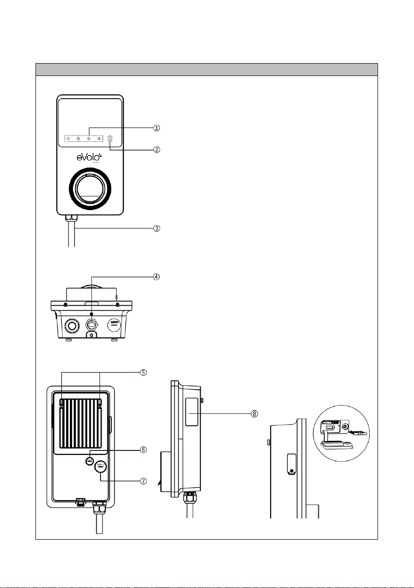
3. Product Overview
Features
Front View
1. LED Indicators (from left to
right):
•Power LED
•Internet Connection
LED
•Charging LED
•Bluetooth Connection
LED
2. RFID LED icon
3. Power Cable
Bottom View
4. RJ45 Ethernet Port
Rear and Side View
5. Mounting Lugs
6. Data Cable entry
7. Power Cable entry
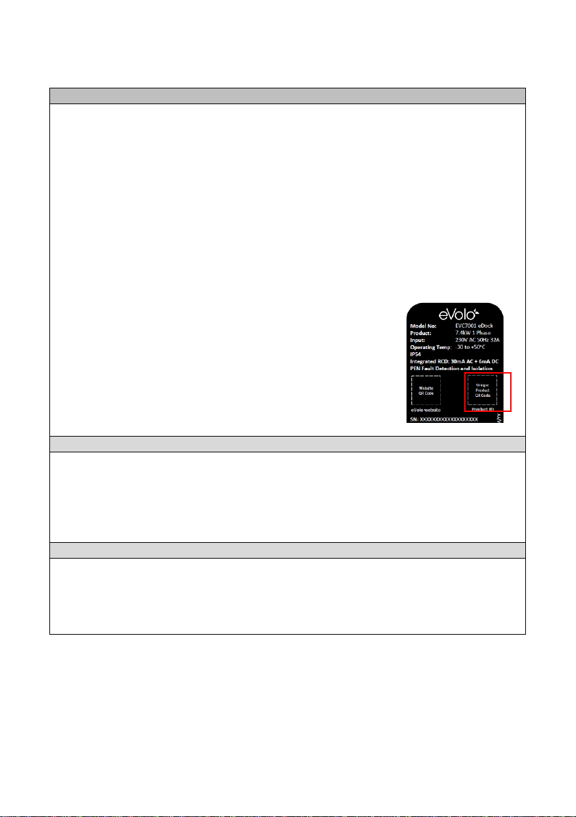
8. Product Label –contains
eVolo website QR code and
unique product QR code
4G option (standard size)

7
4. Packing List
Parts Included
Before you begin, ensure all the parts below can be found within the packaging box:
Charge
Point
Wall
Mounting
Bracket
6 x 50mm
Screws (x2)
Wall Plugs
(x2)
M5 x 10mm
Screw (x1)
Waterproof
Ethernet
Cable Gland
M16 Closed
Grommet
M25 Closed
Grommet
Torx
Security
Key:
T10 (x1)
T25 (x1)
RFID cards
(x2)

8
5. Installation Design
Design Considerations
The eVoomXT is designed for use in communal areas where the the user may be billed for
the electricity being used to charge their EV.
No diversity to be allowed.
Dedicated Distribution Board
If multiple charge points are fed from a dedicated landlords 3-phase distribution board
(with no other loads connected), the maximum current that an EV can draw automatically
adjusts depending upon the number of EV’s being charged.
To achieve this, the charge points must be ‘grouped’ together with one set to ‘Primary’ and
a maximum of 8 ‘Secondaries’ within the Config APP. The ‘Primary’ charge point must have
a cabled internet connection and the other charge points need to be set to ‘Secondary’ and
either have a cabled or Wi-Fi internet connection. The maximum current available on that
phase for the charge points that are within that group needs to be set on the ‘Primary’
charge point within the Config APP.
If these charge points are connected on single phase radials, they should be distributed
evenly across the phases and can deliver 7.4kW maximum. One charge point per phase
needs to be set to ‘Primary’ and the others to ‘Secondary’.
This principal applies for a 3-phase supply to each charge point, which can deliver a 22kW
maximum, and all these charge points need to be grouped. Only one charge point is set to
‘Primary’ with a maximum of 8 ‘Secondary’ chargers.
Distribution Board feeding EV’s and other loads
If charge points are connected to a distribution board that also feeds other loads, MID
energy meters are needed to monitor the current that the distribution board is drawing.
The charge points need to be ‘grouped’, configured into ‘Primary’ and ‘Secondary’ and have
internet connections as above. A RS485 data cable connects the MID energy meter and the
‘Primary’ charge point.
The maximum current available to the distibution board needs to be set on the ‘Primary’
charge point within the Config APP. The ‘Primary’ charge point will monitor current being
drawn against maximum current available, and manage the remaining availablecurrent
between EV’s connected to these charge points.
Loss of internet
If the internet connection fails, the charge points will deliver a maximum of 6A.

9
6. Installation
Location of EV Charge Point
•Install your charge point on a flat and vertical surface capable of supporting its weight
(the charge point has a weight of approximately 4.2kg)
•Position the charge point in a location where it is not vulnerable to being damaged
•The eVoomXT charge point is supplied with a combined power and RS485 cable;
termination in a suitable enclosure should be considered
•Data cabling should also be considered and requires a RJ45 plug to connect to the
charge point
•The car charge point can be mounted on a suitable post
•If using Wi-Fi for communication, signal strength needs to be determined before
installation commences
•For a more reliable internet connection, it is recommended that an Ethernet cable is
routed to the charge point
•Consider the charge point location relative to the vehicle, i.e. whether the EV’s
charging cable will sufficiently reach the vehicle’s charging port
Cable Entry
•The eVoomXT is fitted with a supply cable for
terminating in a separate junction box
•This cable has combined RS485 conductors
•The rear cable entry for data cables (A) is
recommended. Alternatively, the charge point
has an external RJ45 connection (B) at the
bottom
Installation
1. Fix the mounting bracket in the required
position, noting the correct orientation
•It is recommened that the socket height is 700
–1000mm (as recommended in PAS1899)
•Use the 6mm screws and wall plugs supplied
to fix to a solid surface
Wall plugs require a 8mmØ hole x 50mm
If fitting a data cable from the rear, move to Step 2,
if not move to step 6.
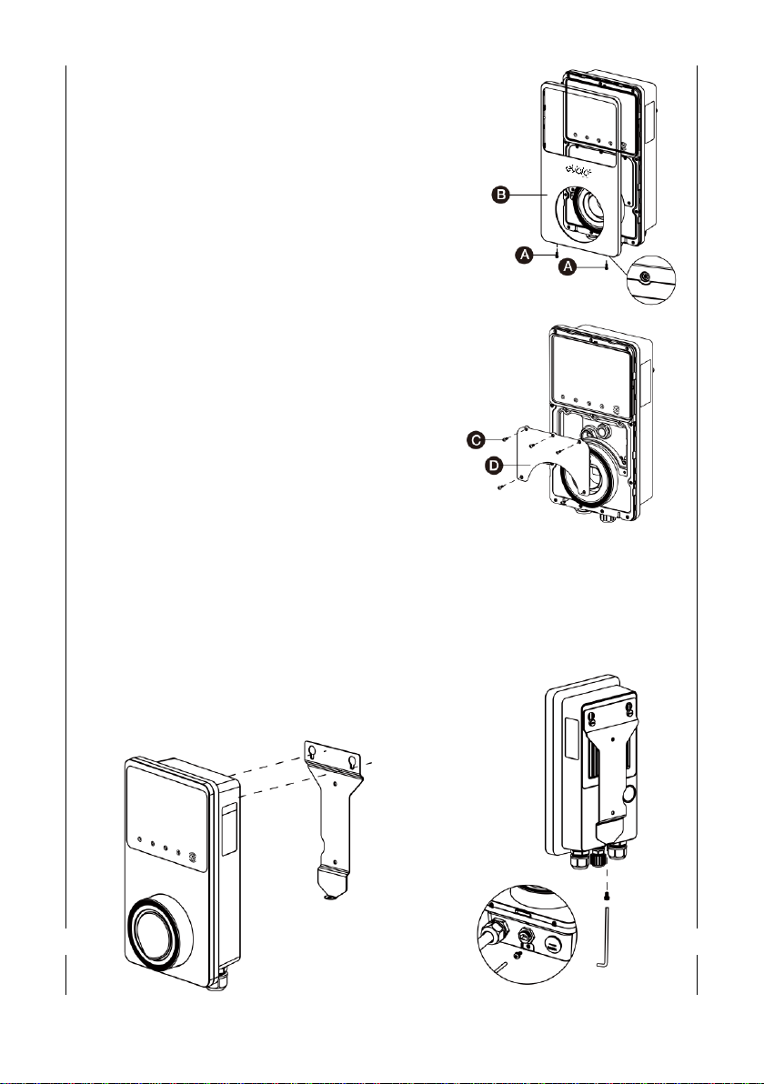
10
2. Remove the facial cover
•Remove the two screws (A) at the bottom of
the cover with the screwdriver type T10
•Unclip the cover (B) from the bottom
3. Remove the terminal cover
•Unscrew the five screws (C) to remove the
inner terminal cover (D).
4. Connect/Terminate Data Cables
•Remove the blanking plugs from the rear cable
entry points and replace glands or grommets
as required
•For Cat5e/6 cable - remove existing connector
(which links to the port at the bottom of the
charge point) and connect new connector
•For RS485 –again, remove and isolate existing
conductors, terminate new conductors
5. Reinstate the terminal cover and facia cover
6. Hook the charge point onto the mounting
bracket and tighten the bottom M5 x 10mm
securing screw
11
7. Terminate Mains Cable
•Connect the below wires:
•Earth (PE): green/yellow striped
•Neutral (N): blue
•Live (L1): brown
•Live (L2): black (3-phase)
•Live (L3): grey (3-phase)
•The cable has RS485 conductors combined –terminate these if
required, otherwise terminate in separate terminal block or wrap
with insulation tape
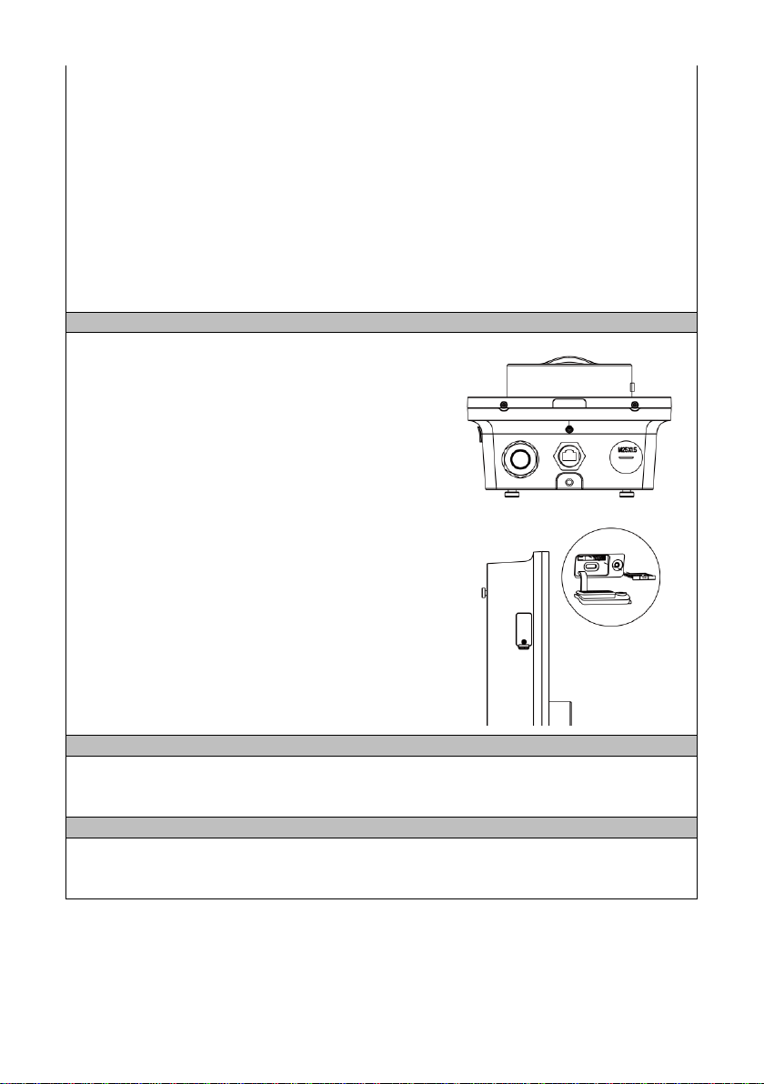
Internet Connection
Ethernet Cable
The ethernet cable can be plugged into the port at
the bottom of the product.
Alternatively, the rear cable position can be used.
In this case, remove the cable plugged into the port
under cover (Q)
•Insert the Ethernet cable through the M16
grommet from the back entry
•Connect the Ethernet cable to the port
4G Connection
If a cabled connection is not possible, a 4G
connection can be obtained by inserting a 4G SIM
card into the slot on the left hand side of the charge
point.
RS485 Communication
RS485 communication cable, e.g. from an energy meter, CT clamp, is terminated on the
rear of the EV charge point, below the RJ45 data connector.
Electrical Installation Testing
The charge point should be disconnected from the installation during insulation resistance
testing.
12
7. Commissioning the EV Charge Point
Commissioning
The eVolo EV Charge Point must be set up and commissioned by an approved installer.
The charge point should be disconnected from the installation during insulation resistance
testing.
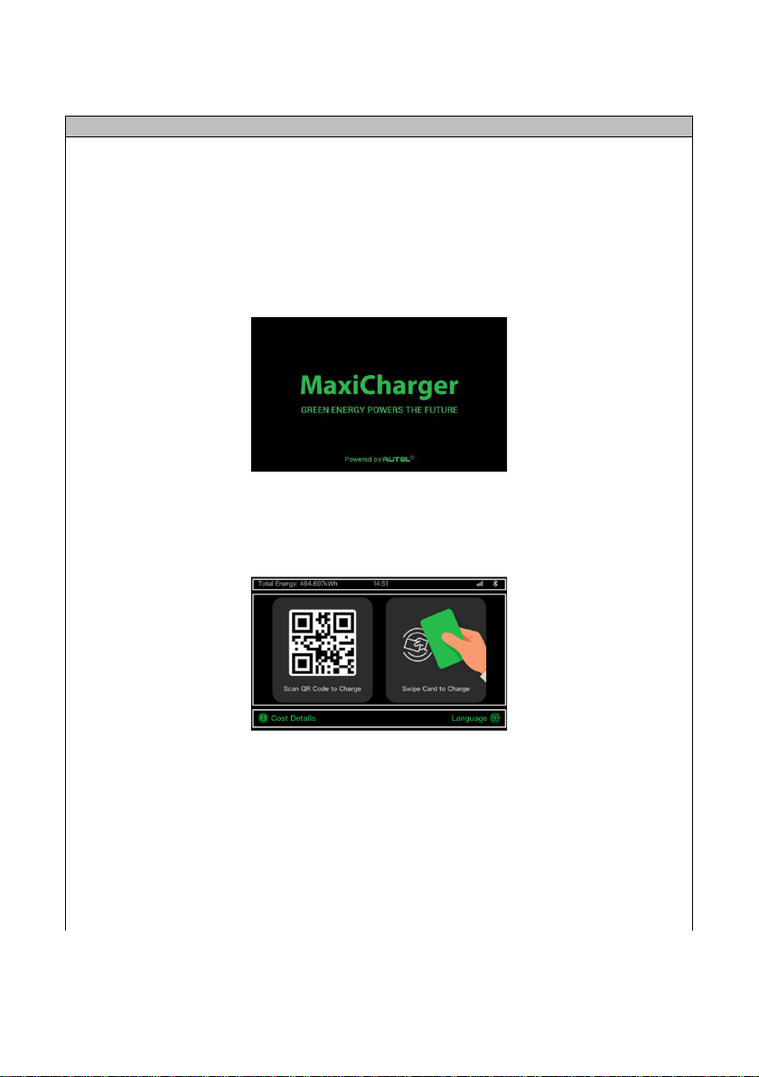
•When power is initally applied to the charge point:
•The loading screen will appear:
•The power LED should illuminate green and will go through a series of self-checks
•If the Charging LED illuminates yellow or red, see LED Indicators In Opertor User
Manual section below. If the problem persists, contact Technical Support
•Following boot up, the touchscreen displays the home/standby screen
The QR code on the home/standby screen is the product ID
The EV Charge Point requires the Autel Config commissioning APP to be downloaded from
www.evolo-uk.com. The APP is password protected.
If an internet connection is not available from the property or a 4G connection via a data
SIM card not be available, the charge point can be commissioned using a mobile device
which is Bluetooth enabled and a mobile data connection.

13
1. Ensure Bluetooth on the mobile device is enabled
2. Add and scan the Product ID QR code which is on the rating label on the side of the
product
3. If prompted, enter the unique PIN number
•The PIN can be found on page 3 of this Installation and Operation Manual
•The Product serial number number appears at the top your screen
4. Set the following by selecting each parameter:
Parameter
Action
Wi-Fi Connection
•If no internet connection, ignore this parameter
•If internet connection is hardwired, ignore this
parameter
•If internet connection is wireless, select ‘Add
Network’ and follow the on screen prompt to add a
wireless network
•Press Back(<) to return to the parameters menu
Charger location
•Verify the charger location on the map within the APP
(assuming location services switched on), and set as
required
•Select ‘OK’ to save setting and return to the
parameters menu
Charge Current Limit
•Select maximum charging current as determined by
the installation/circuit design
•Select ‘OK’ to save settings and return to the
parameters menu
Randomised Delay
•This must be set to On
•Press Back(<) to return to the parameters menu
Schedule
•This must be set to On
Firmware Update
•Check firmware is up to date
OCPP
(Open Charge Point
Protocol)
•This defaults to the Autel® cloud
•Alternative cloud management systems can be chosen
from dropdown menu
•Do not change without consulting eVolo Technical
Support
APN
•This changes the mobile Access Point Network that
the charge point is connected to. If the charge point
is connected to the internet via a 4G data SIM card,
APN settings may need to be manually configured.
•To adjust the APN settings, select the APN menu,
input the APN name as required by the SIM
manufacturer and choose the internet protocol and
authentication type

14
Local DLB
•Select: Set as ‘Primary Charger’
•If more than one eVolo charge point is connected to a
network, only one can be set as ‘Primary Charger’
•If external load management hardware has not been
installed, e.g. smart meter, CT clamp, the Smart Meter
switch must be set to Off
•Total Charger Quantity –enter the quantity of EV
Charge Points supplied from the consumer unit,
usually set to 1
•Maximum Available Power (kW) –set to same figure
as entered in Charge Current Limit, if only one charge
point is connected to the properties supply
•Number of Phases –select Single-phase
RCD Test
•The charge point simulates an earth fault –following
on screen instructions
Press Back(<) to return to the main menu showing the EV
charge point serial number located in the ‘Home’ tab
5. The charge point should be tested using an EV charge point tester
After commissioning, the mobile device must be unlinked from the EV charge point by
pressing unlink located in the ‘Bluetooth connected’ field
Note: If power to the charge point is lost during commissioning, Bluetooth data connection
to the mobile device will be lost and the commissioning APP will disconnect from the
charge point.
Once power is restored, please reconnect to the charge point by selecting the serial
number from the ‘Home’tab

15
8. Trouble Shooting –Commissioning
Item
Problems
Solutions
1
No power
•Check the incoming supply to the charger
•Check the charge point is connecting the mounting base
correctly
2
No network
•Check the RJ45 connector is fully inserted
•Check the network cable continuity
•Check the network settings
3
No Wi-Fi
connection
•Check the network frequency is 2.4GHz
•Check the Wi-Fi signal strength
•Check the network security settings
•Reboot the Wi-Fi router
4
No Bluetooth
connection
•Make sure the Bluetooth is enabled on your mobile
device and the charge point is powered on and
operating properly
•‘Forget’ the charge point in the Bluetooth settings on
your mobile device and pair the charge point to your
device via Bluetooth again.
•If the problem persists, contact customer support
5
Unable to register
charge point
•Check whether the QR code on the charger is consistent
with the QR code on the Installation & Operation
Manual. If so, make sure the Bluetooth is enabled on
your mobile device; if not, contact customer support.
6
Earth fault
•Make sure the charge point is earthed correctly.
See FAQ within the Autel® Charge APP for full list

16
9. Product Specification
Specification
AC Charging Output
Maximum 7.4kW/22kW
Input Supply
230V/410V AC 50 Hz 32Amax. single or three phase
Input
1.5m flexible combined 3-phase 6mm2power & RS485 data
cable
Earthing Systems
TNC-S or TT
Connector Type
Untethered Type 2 Socket
Indications
4 LEDs multicolored
Touch Screen LCD Display
5” Touch LCD screen
Metering
Built in meter IC, ± 1 % (accuracy)
Integrated RCD
AC 30mA + DC 6mA
Protection
•Overcurrent
•PEN fault detection and isolation
•Integrated surge protection
Connectivity
•Ethernet (RJ45)
•Bluetooth
•Wi-Fi (2.4GHz)
•RS485
•4G
Communication Protocols
OCPP 1.6J
Mounting
Wall-mounted or floor using an optional pedestal
Enclosure Ratings
IP54, IK08, indoor or outdoor installation
Operating Temperature
-30 to +50°C
Storage Temperature
-40 to +70°C
Safety and Compliance
•BS IEC/EN 61851-1
•BS EN 61851-22
•BS EN 62196-1
•BS EN 61008-1
•BS EN 60947-2
•BS IEC 62955
•The Electric Vehicles (Smart Charge Points) Regs.2021
Codes and Standards
UKCA, CE (TUV)
Load management
•The maximum charging current can be set within the
commissioning APP
•Additional hardware, e.g. MID energy meter, can be used
to manage the current to the EV depending the available
supply at a point in time

17
OPERATOR USER MANUAL
1. Overview
Description
The eVolo AC charge point is designed to charge electric vehicles (hereinafter called EVs) at
your premises.
Your eVolo EV charge point is a connected product (as required by the Regulations) and
requires an internet connection. The charge point needs to operate via a smart phone APP
where an account needs to be registered.
The charge point default control setting is for the Autel® Charge APP. The charge point can
be operated by other software as required by the CPO (Charge Point Operator).
Intended Use
The eVolo AC charge point is intended for charging of EVs only. It is suitable for both indoor
and outdoor use.
This product must be installed and commissioned by an approved eVolo installer.
2. Safety Instructions
Safety Instructions
CAUTION Use of the EV charge point may affect the operation of or impair any
medical or implantable electronic devices, such as an implantable
cardiac pacemaker or an implantable cardiovascular defibrillator.
Before using the EV charge point, check with your electronic device
manufacturer regarding the effects that charging an EV may have on
such electronic devices.
18
3. Charge Point Manager Setup
Management Software
The charge point is set by default to Autel’s cloud management software.
If using the Autel cloud management software, the user must download the Autel Charge
APP.
If the charge point has been set to an alternative cloud management software, this should
have been set up during commissioning and their APP must be downloaded by the user.
Accordingly, the user will need to be instructed which APP to download and use.
Instructions within this APP will need to be followed.
When required, the unique product ID QR code can be found
on the home/standby screen and on the product label on
the side of the product, shown in red in the diagram.
Billing
When the electrical supply is being supplied by the landlord/3rd party, the charge point
account is billed for the electricity being used via the CPO. The cloud management
software can be used to determine the amount electricity being used.
RFID Cards
The charge point can be controlled by the RFID cards that are supplied with it.
Additional cards can be obtained from evolo-uk.com.

19
4. Using the EV Charge Point
Operation
From the home/standby screen, the Cost Details can be viewed and the language can
be changed.
Button
Tap to confirm the information on the screen
Cost Details
Tap to view the charging cost
Language
Tap to choose your language for the charger
Stop
Tap to stop a charge session
Back
Tap to return to the previous screen
Start charging options
1. Use the APP
2. Use the RFID card
3. Connect the EV by inserting the charging cable –EV will start charging at the scheduled
time
The charging LED on the charger should flash green.
Stop charging options
1. Use the APP
2. Use the RFID card
3. Schedule time
4. Stop button on the LCD touch screen, if enabled
20
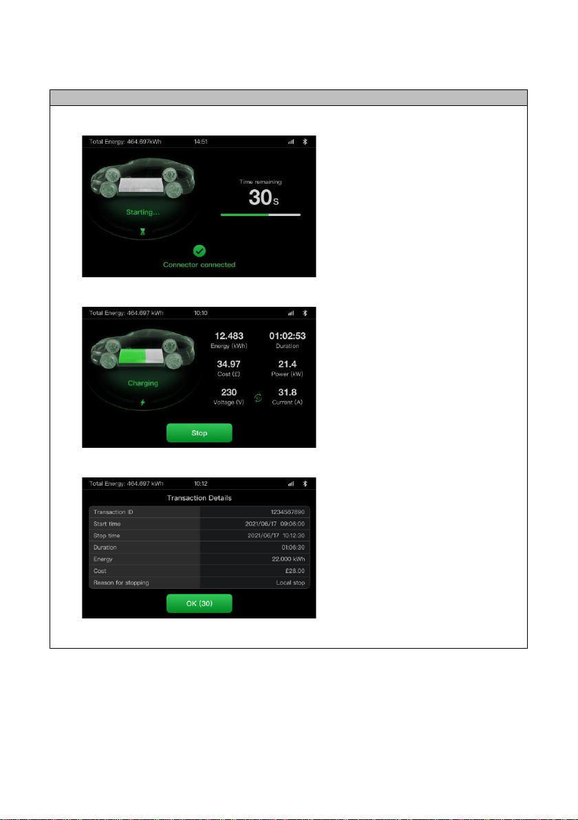
Screens
Preparing to Charge Screen
Charging Screen
Transaction Details Screen
Display subject to change due to firmware updates
Table of contents


