Project EV EVA-22S-SE-RFID User manual
22KW
User Manual
A Complete Guide From
Installation To Operation
EVA-22S-SE-RFID / EVA-22S-SE-RFID-4G
EVA-22S-SE-RFID-C / EVA-22S-SE-RFID-4G-C
Three Phase AC Charger
User Manual
Information Correct as of 05/23

Disclaimer
22KW
Thank you for using Project EV charging equipment!
EVA series intelligent single-phase AC charger is a power supply device that uses
professional and advanced technology to provide energy supply to electric
vehicles, it also has friendly man-machine interface and versatile functions of
control, billing, and communication. The charger can be connected to a
back-office server to utilise the functions of diversified communication options,
including wired Ethernet, WIFI, 4G is available for back-office server connection.
We sincerely hope that this product can meet your needs and will continuously
improve the quality of our products.
Disclaimer
This user manual is copyrighted by Project EV. (Hereinafter referred to as “ATESS
Power Technology”). No company or person may extract or copy part or all
of this user manual without the written permission of ATESS Power
Technology. Content must not be transmitted in any form, including
materials and publications.
All rights reserved. ATESS Power Technology has the final right to
interpret this user manual. The information in this manual is subject to
change without notice.
Product Features
22KW
We pack our products with the best features, so you can
make the most out of your EV charger.
All of our 7.3kW fast charge points, up to our 40kW rapid chargers, are all OZEV
approved. All of our chargers are OCPP 1.6 compliant, all meeting UK & European
standards, and they are all covered by a market leading five-year warranty.
Features Packed as
Standard
PRO EARTH
NO SPIKE REQUIRED
CABLE LOCK
SYSTEM
18TH EDITION
COMPLIANT
5 YEAR
WARRANTY
ONBOARD RCBO
ISOLATION
DYNAMIC
LOAD MANAGEMENT
OFF-PEAK
TIME SHIFTING
SOLAR
COMPATIBLE
Project EV are proud to be one of the most competitively priced electric vehicle charge
point manufacturers on the market, with a highly versatile range, we are positive
Project EV can solve all your charging needs.
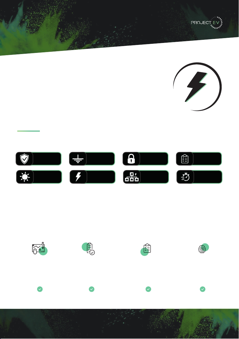
Key Features
Compact Design
Attractive appearance, simple
but elegant
Full Protection
Full electrical protection, over/under
temperature protection, etc
Global Standard
OCPP v1.6 open charge point
protocol. IEC 62196 type II
connector
Intelligent
Intelligent power adjustment,
emergency stop, WiFi/APP/ethernet
monitoring
2

Contents
22KW
- Disclaimer
- Product Features
- Product Description
- Specification
EVA-22S-SE-RFID / EVA-22S-SE-RFID-C
EVA-22S-SE-RFID-4G / EVA-22S-SE-RFID-4G-C
- Packaging List
- Installation
Wall Mounted
Pole Mounted
CT Clamp
- Load Management
- Modbus Meter
- Configuring a laptop for commissioning
- Laptop Commissioning settings explained
- Project EV Standard App
Using the App
Creating a new account
Commissioning Process
EV Smart Charge Point Regulations
App Status
Charger Control Methods
Scheduling a charge
Making your unit bespoke
Account Management
- Troubleshooting
- Further Support
- Warranty
- FAQ’s
3
1
2
4
5-6
7
9-11
12
13
14
15- 16
17-19
20-36
37-39
40
41-44
45-46

Product Description
22KW
4
1
2
3
4
5
6
7
8
9
10
11
12
13
1. LOGO and logo backlight
2. LCD display
3. RFID ready
4. Status indicator
5. Emergency stop button
6. Forced On/Off button
7. Socket outlet (plug holder for cabled
version)
8. Side window and nameplate
9. Mounting bracket
10. WiFi/4G Antenna
11. Side window/RCD
12. Waterproof cable gland for AC input
cables
13. Waterproof cable gland for
communication wires

3 x CT Clamp (EV-CTClamp)
or 3 Phase Modbus Meter
Required (EV-TPM)
3 x CT Clamp (EV-CTClamp)
or 3 Phase Modbus Meter
Required (EV-TPM)
Protection
Over voltage protection
Under voltage protection
Over load protection
Short circuit protection
Earth leakage protection
Over-temp protection
Surge protection
PEN fault protection
Anti Tamper Switch
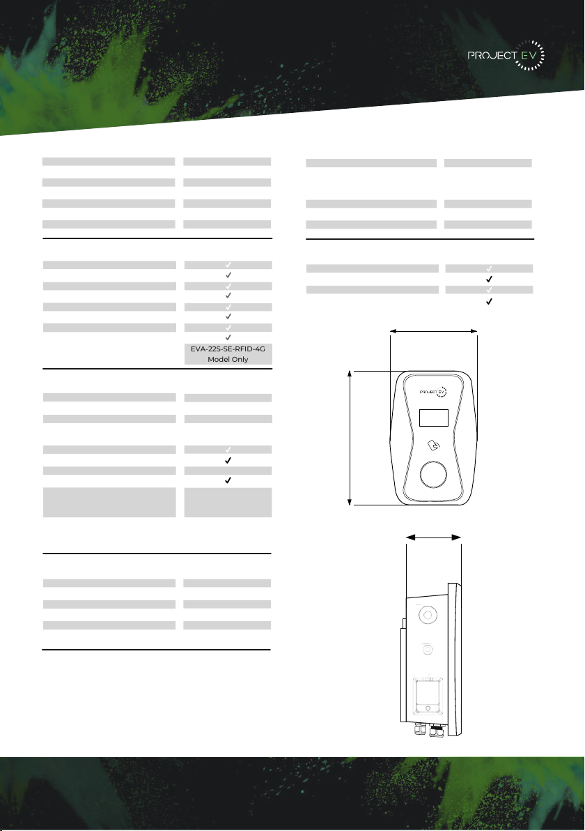
Specification
EVA-22S-SE-RFID / EVA-22S-SE-RFID-C
5
IP65
-25ºC~+50ºC
0-95% non-condensing
Natural air cooling
<8W
IK10
Protection degree
Environment temperature
Relative humidity
Cooling
Standby power consumption
IK Rating
Working Environment
Function & Accessory
Yes
Yes/Yes
Type 2 (socket)
LCD
Ethernet/WIFI
Outlet Type
RCBO
LED Indicator light
Emergency stop button
Intelligent power adjustment
RFID
Solar Mode
Load Management
Opt.
Type A +6mA DC fault
current protection
(Equivalent to Type B)
CE
SA8000 Accredited
OZEV Approved
UKCA
Certification
Mechanical
300/465/170mm
<9KG
Standard
Opt. EV-FLRSTAND
Opt. EV-GMEVA-S-2
Wall-mounting
Floor-pole
Grount-mounting
Dimension (W/H/D)
Weight
Mounting & Accessories
Input Amps
Input voltage
Input frequency
Output voltage
Max. output power
Max. output current
Charging interface type
32a Three Phase
415V AC
50HZ
415 AC
22KW
32A per phase
IEC 62196-2, Type 2
Input & Output
Mounting Accessories
Wall-mounting
Ground-mounting pole
Yes
Opt
Input & Output
Input voltage
Input frequency
Output voltage
Max. output power
Max. output current
Charging interface type
Function and Accessory
LCD
Ethernet/WIFI/4G
Payment support
Connector
RCD
LED Indicator light
Emergency stop button
Intelligent power adjustment
RFID
Mechanical
Dimension (W/H/D)
Weight
Working environment
Protection degree
Environment temperature
Relative humidity
Maximum altitude
Cooling
Standby power consumption
Protection
Over voltage protection
Under voltage protection
Over load protection
Short circuit protection
Earth leakage protection
Over-temp protection
Surge protection
400V AC
50Hz
400V AC
22KW
32A Per Phase
IEC 62196-2, Type ll
Yes
Yes
Yes
Yes
Yes
Yes
Yes
Yes
Yes/Yes/Opt
RFID/QR(standard)
Socket
Type A + 6mA DC fault current
protection (Equivalent to Type
B)
Yes
Yes
Opt
Yes
IP65
-20ºC ~ +50ºC
0-95% non-condensing
<2000m
Natural air cooling
<8W
300/465/170mm
<10KG
CE
Certification
Certificate
300
466
170
EVA-22S-SE-RFID-C
Model Only
Specification
EVA-22S-SE-RFID-4G / EVA-22S-SE-RFID-4G-C
6
IP65
-25ºC~+50ºC
0-95% non-condensing
Natural air cooling
<8W
IK10
Protection degree
Environment temperature
Relative humidity
Cooling
Standby power consumption
IK Rating
Working Environment
Protection
Over voltage protection
Under voltage protection
Over load protection
Short circuit protection
Earth leakage protection
Over-temp protection
Surge protection
PEN fault protection
Anti Tamper Switch
Function & Accessory
Yes
Yes/Yes
Type 2 (socket)
LCD
Ethernet/4G
Outlet Type
RCBO
LED Indicator light
Emergency stop button
Intelligent power adjustment
RFID
Solar Mode
Load Management
Opt.
3 x CT Clamp (EV-CTClamp)
or 3 Phase Modbus Meter
Required (EV-TPM)
3 x CT Clamp (EV-CTClamp)
or 3 Phase Modbus Meter
Required (EV-TPM)
Type A +6mA DC fault
current protection
(Equivalent to Type B)
CE
SA8000 Accredited
OZEV Approved
UKCA
Certification
Mechanical
300/465/170mm
<9KG
Standard
Opt. EV-FLRSTAND
Opt. EV-GMEVA-S-2
Wall-mounting
Floor-pole
Ground-mounting
Dimension (W/H/D)
Weight
Mounting & Accessories
Input Amps
Input voltage
Input frequency
Output voltage
Max. output power
Max. output current
Charging interface type
32a Three Phase
415V AC
50HZ
415V AC
22KW
32A per phase
IEC 62196-2, Type 2
Input & Output
Mounting Accessories
Wall-mounting
Ground-mounting pole
Yes
Opt
Input & Output
Input voltage
Input frequency
Output voltage
Max. output power
Max. output current
Charging interface type
Function and Accessory
LCD
Ethernet/WIFI/4G
Payment support
Connector
RCD
LED Indicator light
Emergency stop button
Intelligent power adjustment
RFID
Mechanical
Dimension (W/H/D)
Weight
Working environment
Protection degree
Environment temperature
Relative humidity
Maximum altitude
Cooling
Standby power consumption
Protection
Over voltage protection
Under voltage protection
Over load protection
Short circuit protection
Earth leakage protection
Over-temp protection
Surge protection
400V AC
50Hz
400V AC
22KW
32A Per Phase
IEC 62196-2, Type ll
Yes
Yes
Yes
Yes
Yes
Yes
Yes
Yes
Yes/Yes/Opt
RFID/QR(standard)
Socket
Type A + 6mA DC fault current
protection (Equivalent to Type
B)
Yes
Yes
Opt
Yes
IP65
-20ºC ~ +50ºC
0-95% non-condensing
<2000m
Natural air cooling
<8W
300/465/170mm
<10KG
CE
Certification
Certificate
300
466
170
Mounting Accessories
Wall-mounting
Ground-mounting pole
Yes
Opt
Input & Output
Input voltage
Input frequency
Output voltage
Max. output power
Max. output current
Charging interface type
Function and Accessory
LCD
Ethernet/WIFI/4G
Payment support
Connector
RCD
LED Indicator light
Emergency stop button
Intelligent power adjustment
RFID
Mechanical
Dimension (W/H/D)
Weight
Working environment
Protection degree
Environment temperature
Relative humidity
Maximum altitude
Cooling
Standby power consumption
Protection
Over voltage protection
Under voltage protection
Over load protection
Short circuit protection
Earth leakage protection
Over-temp protection
Surge protection
400V AC
50Hz
400V AC
22KW
32A Per Phase
IEC 62196-2, Type ll
Yes
Yes
Yes
Yes
Yes
Yes
Yes
Yes
Yes/Yes/Opt
RFID/QR(standard)
Socket
Type A + 6mA DC fault current
protection (Equivalent to Type
B)
Yes
Yes
Opt
Yes
IP65
-20ºC ~ +50ºC
0-95% non-condensing
<2000m
Natural air cooling
<8W
300/465/170mm
<10KG
CE
Certification
Certificate
300
466
170
EVA-22S-SE-RFID-4G
Model Only

Packaging List
22KW
Number Name Quantity Other
Comments
3
1
2
4
5
6
1
1
1
1
Charger
Quality Certificate
Mounting Bracket
ST6.3 x 40
Stainless Steel Hex Head
Self Drilling Screws
12 X 46
Plastic Expansion Plugs
RFID Card
Attached to
bracket
RFID
function will
be
equipped
with user
card
7
4
4

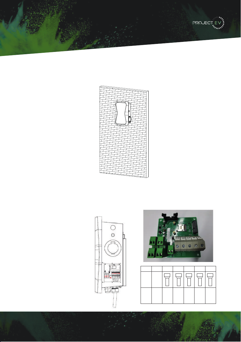
Installation
Wall Mounted
Mount on a Wall
1. Open the packaging, you will see the charge point, mounting bracket (attached to the
charger), and a bag of mounting accessories which will also include the RFID card.
2. Remove the mounting bracket from the charge point, use it as a template to mark the
position of the 10mm drill holes. Drill the holes and hammer the expansion bolts in the
accessories bag into the holes. Then use the fixings provided to fit bracket to wall.
,, 3DFNDJLQJOLVW
1R 1DPH 4W\ 5HPDUN
&KDUJHU
8VHUPDQXDO
4XDOLW\FHUWLILFDWH
0RXQWLQJEUDFNHW
&DEOHKRRN
67;
6WDLQOHVVVWHHOKH[KHDG
VHOIGULOOLQJVFUHZV
;
3ODVWLFH[SDQVLRQSOXJV
)RUFDEOHGYHUVLRQ
IRUVRFNHWYHUVLRQIRUFDEOHG
YHUVLRQRIWKHVFUHZVDUH
IRUFDEOHKRRNIL[LQJ
IRUVRFNHWYHUVLRQIRU
FDEOHGYHUVLRQRIWKHSOXJV
DUHIRUFDEOHKRRNIL[LQJ
,,, ,QVWDOODWLRQDQGZLULQJ
0RXQWRQDZDOO
2SHQ WKHSDFNDJLQJ\RX¶OOVHHDFKDUJHSRLQWDPRXQWLQJEUDFNHWD XVHUPDQXDO
DQGDEDJRIPRXQWLQJDFFHVVRULHV7KHUHLVDOVRDQ5),'FDUGLIWKHFKDUJHSRLQWLV5),'
YHUVLRQ)RUFDEOHGYHUVLRQDFDEOHKRRNHULVDOVRLQFOXGHGLQVLGH
5HPRYHWKH PRXQWLQJ EUDFNHWIURPWKH FKDUJH SRLQWXVHLW DV DWHPSODWHWR PDUN
WKH SRVLWLRQ RI WKH GULOO KROHV 'ULOO WKH KROHV DQG KDPPHU WKH H[SDQVLRQ EROWV LQ WKH
DFFHVVRULHVEDJLQWRWKHKROHV7KHQIL[WKHPRXQWLQJEUDFNHWRQWRWKHZDOO
8VHUFDUG 5),'IXQFWLRQZLOOEHHTXLSSHG
ZLWKXVHUFDUG
II. Packaging List III. Installation and wiring
No. Name Qty Remark
1Charger 1
2 User manual 1
3 Quality certicate 1
4 Mounting bracket 1
5 Cable hook 1 For cables version
6
ST6.3X40
Stainless steel hex-head
self drilling screws
4-7
4 for socket version, 7 for cabled
version (3 of the 7 screws are for
cable hook xing
712x46
Plastic expansion plugs 4-7
4 for socket version, 7 for cabled
version (3 of the 7 screws are for
cable hook xing
8 User card 1 RFID function will be equipped with
user card
3.1 Mount on a wall
3.1.1 Open the packaging, you’ll see a charge point, a mounting bracket, a user manual
and a bag of mounting accessories. There is also an RFID card if the charge point is
RFID version. For cabled version, a cable hooker is also included inside.
3.1.2 Remove the mounting bracket from the charge point, use it as a template to mark
the position of the drill holes. Use the expansion bolts from the accessories bag and
hammer these into the drilled holes. Then x the mounting bracket onto the wall.
6 7
8
Mounting Accessories
Wall-mounting
Ground-mounting pole
Yes
Opt
Input & Output
Input voltage
Input frequency
Output voltage
Max. output power
Max. output current
Charging interface type
Function and Accessory
LCD
Ethernet/WIFI/4G
Payment support
Connector
RCD
LED Indicator light
Emergency stop button
Intelligent power adjustment
RFID
Mechanical
Dimension (W/H/D)
Weight
Working environment
Protection degree
Environment temperature
Relative humidity
Maximum altitude
Cooling
Standby power consumption
Protection
Over voltage protection
Under voltage protection
Over load protection
Short circuit protection
Earth leakage protection
Over-temp protection
Surge protection
400V AC
50Hz
400V AC
22KW
32A Per Phase
IEC 62196-2, Type ll
Yes
Yes
Yes
Yes
Yes
Yes
Yes
Yes
Yes/Yes/Opt
RFID/QR(standard)
Socket
Type A + 6mA DC fault current
protection (Equivalent to Type
B)
Yes
Yes
Opt
Yes
IP65
-20ºC ~ +50ºC
0-95% non-condensing
<2000m
Natural air cooling
<8W
300/465/170mm
<10KG
CE
Certification
Certificate
300
466
170
Installation
Wall Mounted
3. Mount the charge point onto the bracket, and fix it with the 2 screws at the bottom of a
charge point. This will secure the charger to the bracket.
4. Crimp the below, shown insulated ferrule or ring terminals on the end of the AC input
wires. Connect the wires into the terminal block of the charge point as below. Check the
wiring and then close the RCBO in the side window. Close the side window with the cover,
then the wiring is done.
3XWWKHFKDUJHSRLQWRQWRWKHEUDFNHWDQGIL[LWZLWKWKHVFUHZVDWWKHERWWRPRI
WKHFKDUJHSRLQW7KHLQVWDOODWLRQLVGRQH
&ULPSWKHEHORZVKRZQLQVXODWHGIHUUXOHRUULQJWHUPLQDOVRQWKHHQGRIWKH$&LQSXW
ZLUHV&RQQHFWWKHZLUHVLQWRWKHWHUPLQDOEORFNRIWKHFKDUJHSRLQWDVEHORZ&KHFNWKH
ZLULQJDQGWKHQFORVHWKH5&'LQWKHVLGHZLQGRZ&ORVHWKHVLGHZLQGRZZLWKWKHFRYHU
WKHQWKHZULQJLVGRQH
0RXQWRQDSROH
2SHQWKHSDFNDJLQJRIWKHSROHWDNHRXWWKHSROHDQGPRXQWLQJDFFHVVRULHV
7KHSROHPXVWEHLQVWDOOHGRQDKDUGVXUIDFHFRQFUHWHVXUIDFHLVUHFRPPHQGHGLW
FDQDOVREHPRXQWHGRQDVROLGJURXQG'ULOOKROHVDFFRUGLQJWRWKHUHTXLUHPHQWVPDUNHG
RQWKHLOOXVWUDWLRQIRUIL[LQJH[SDQVLRQEROWV
)L[WKHSROHRQWRWKHKROHVZLWKH[SDQVLRQEROWV7KHLQSXWFDEOHVVKDOOJRLQWRWKH
SROH IURP WKH ERWWRP PLGGOH DUHD DQG FRPH RXW RI LW IURP WKH DUHD EHORZ WKH FDEOH
KRRNHU
3.1.3 Put the charge point onto the bracket, and x it with the 2 screws at the bottom of
the charge point. The installation is done.
3.1.4 Crimp the insulated ferrule or ring terminals on the end of the AC input wires.
Connect the wires into the terminal block of the charge point as below. Check the
wiring and then close the RCD in the side window. Close the side window with the
cover, then the wiring is completed.
3.2.2 The pole must be installed on a hard surface, concrete surface is recommended,
it can also be mounted on a solid ground. Drill holes according to the requirements
marked on the illustration for xing expansion bolts.
3.2.3 Fix the pole onto the holes with expansion bolts. The input cables shall go
into the pole from the bottom middle area and come out of it from the area below the
cable hooker.
3.2 Mount on a pole
3.2.1 Open the packaging of the pole, take out the pole and mounting accessories.
8 9
9
Terminal 22K
22KWire ≥16m²
≥AWG5
≥16m²
≥AWG5
≥16m²
≥AWG5
≥16m²
≥AWG5
≥16m²
≥AWG5
Model L1 L2 L3 NPE
Disclaimer: All terminals
must be torqued to 5.5Nm.
3XWWKHFKDUJHSRLQWRQWRWKHEUDFNHW DQGIL[LWZLWKWKHVFUHZV DWWKHERWWRPRI
WKHFKDUJHSRLQW7KHLQVWDOODWLRQLVGRQH
&ULPSWKHEHORZVKRZQLQVXODWHGIHUUXOHRUULQJWHUPLQDOVRQWKHHQGRIWKH$&LQSXW
ZLUHV&RQQHFWWKHZLUHVLQWRWKHWHUPLQDOEORFNRIWKHFKDUJHSRLQWDVEHORZ&KHFNWKH
ZLULQJDQGWKHQFORVHWKH5&'LQWKHVLGHZLQGRZ&ORVHWKHVLGHZLQGRZZLWKWKHFRYHU
WKHQWKHZULQJLVGRQH
0RXQWRQDSROH
2SHQWKHSDFNDJLQJRIWKHSROHWDNHRXWWKHSROHDQGPRXQWLQJDFFHVVRULHV
7KHSROHPXVWEHLQVWDOOHGRQDKDUGVXUIDFHFRQFUHWHVXUIDFHLVUHFRPPHQGHGLW
FDQDOVREHPRXQWHGRQDVROLGJURXQG'ULOOKROHVDFFRUGLQJWRWKHUHTXLUHPHQWVPDUNHG
RQWKHLOOXVWUDWLRQIRUIL[LQJH[SDQVLRQEROWV
)L[WKHSROHRQWRWKHKROHVZLWKH[SDQVLRQEROWV7KHLQSXWFDEOHVVKDOOJRLQWRWKH
SROH IURP WKH ERWWRP PLGGOH DUHD DQG FRPH RXW RI LW IURP WKH DUHD EHORZ WKH FDEOH
KRRNHU
3.1.3 Put the charge point onto the bracket, and x it with the 2 screws at the bottom of
the charge point. The installation is done.
3.1.4 Crimp the insulated ferrule or ring terminals on the end of the AC input wires.
Connect the wires into the terminal block of the charge point as below. Check the
wiring and then close the RCD in the side window. Close the side window with the
cover, then the wiring is completed.
3.2.2 The pole must be installed on a hard surface, concrete surface is recommended,
it can also be mounted on a solid ground. Drill holes according to the requirements
marked on the illustration for xing expansion bolts.
3.2.3 Fix the pole onto the holes with expansion bolts. The input cables shall go
into the pole from the bottom middle area and come out of it from the area below the
cable hooker.
3.2 Mount on a pole
3.2.1 Open the packaging of the pole, take out the pole and mounting accessories.
8 9
3XWWKHFKDUJHSRLQWRQWRWKHEUDFNHWDQGIL[LWZLWKWKHVFUHZVDWWKHERWWRPRI
WKHFKDUJHSRLQW7KHLQVWDOODWLRQLVGRQH
&ULPSWKHEHORZVKRZQLQVXODWHGIHUUXOHRUULQJWHUPLQDOVRQWKHHQGRIWKH$&LQSXW
ZLUHV&RQQHFWWKHZLUHVLQWRWKHWHUPLQDOEORFNRIWKHFKDUJHSRLQWDVEHORZ&KHFNWKH
ZLULQJDQGWKHQFORVHWKH5&'LQWKHVLGHZLQGRZ&ORVHWKHVLGHZLQGRZZLWKWKHFRYHU
WKHQWKHZULQJLVGRQH
0RXQWRQDSROH
2SHQWKHSDFNDJLQJRIWKHSROHWDNHRXWWKHSROHDQGPRXQWLQJDFFHVVRULHV
7KHSROHPXVWEHLQVWDOOHGRQDKDUGVXUIDFHFRQFUHWHVXUIDFHLVUHFRPPHQGHGLW
FDQDOVREHPRXQWHGRQDVROLGJURXQG'ULOOKROHVDFFRUGLQJWRWKHUHTXLUHPHQWVPDUNHG
RQWKHLOOXVWUDWLRQIRUIL[LQJH[SDQVLRQEROWV
)L[WKHSROHRQWRWKHKROHVZLWKH[SDQVLRQEROWV7KHLQSXWFDEOHVVKDOOJRLQWRWKH
SROH IURP WKH ERWWRP PLGGOH DUHD DQG FRPH RXW RI LW IURP WKH DUHD EHORZ WKH FDEOH
KRRNHU
3.1.3 Put the charge point onto the bracket, and x it with the 2 screws at the bottom of
the charge point. The installation is done.
3.1.4 Crimp the insulated ferrule or ring terminals on the end of the AC input wires.
Connect the wires into the terminal block of the charge point as below. Check the
wiring and then close the RCD in the side window. Close the side window with the
cover, then the wiring is completed.
3.2.2 The pole must be installed on a hard surface, concrete surface is recommended,
it can also be mounted on a solid ground. Drill holes according to the requirements
marked on the illustration for xing expansion bolts.
3.2.3 Fix the pole onto the holes with expansion bolts. The input cables shall go
into the pole from the bottom middle area and come out of it from the area below the
cable hooker.
3.2 Mount on a pole
3.2.1 Open the packaging of the pole, take out the pole and mounting accessories.
8 9

Mounting Accessories
Wall-mounting
Ground-mounting pole
Yes
Opt
Input & Output
Input voltage
Input frequency
Output voltage
Max. output power
Max. output current
Charging interface type
Function and Accessory
LCD
Ethernet/WIFI/4G
Payment support
Connector
RCD
LED Indicator light
Emergency stop button
Intelligent power adjustment
RFID
Mechanical
Dimension (W/H/D)
Weight
Working environment
Protection degree
Environment temperature
Relative humidity
Maximum altitude
Cooling
Standby power consumption
Protection
Over voltage protection
Under voltage protection
Over load protection
Short circuit protection
Earth leakage protection
Over-temp protection
Surge protection
400V AC
50Hz
400V AC
22KW
32A Per Phase
IEC 62196-2, Type ll
Yes
Yes
Yes
Yes
Yes
Yes
Yes
Yes
Yes/Yes/Opt
RFID/QR(standard)
Socket
Type A + 6mA DC fault current
protection (Equivalent to Type
B)
Yes
Yes
Opt
Yes
IP65
-20ºC ~ +50ºC
0-95% non-condensing
<2000m
Natural air cooling
<8W
300/465/170mm
<10KG
CE
Certification
Certificate
300
466
170
3XWWKHFKDUJHSRLQWRQWRWKHEUDFNHWDQGIL[LWZLWKWKHVFUHZVDWWKHERWWRPRI
WKHFKDUJHSRLQW7KHLQVWDOODWLRQLVGRQH
&ULPSWKHEHORZVKRZQLQVXODWHGIHUUXOHRUULQJWHUPLQDOVRQWKHHQGRIWKH$&LQSXW
ZLUHV&RQQHFWWKHZLUHVLQWRWKHWHUPLQDOEORFNRIWKHFKDUJHSRLQWDVEHORZ&KHFNWKH
ZLULQJDQGWKHQFORVHWKH5&'LQWKHVLGHZLQGRZ&ORVHWKHVLGHZLQGRZZLWKWKHFRYHU
WKHQWKHZULQJLVGRQH
0RXQWRQDSROH
2SHQWKHSDFNDJLQJRIWKHSROHWDNHRXWWKHSROHDQGPRXQWLQJDFFHVVRULHV
7KHSROHPXVWEHLQVWDOOHGRQDKDUGVXUIDFHFRQFUHWHVXUIDFHLVUHFRPPHQGHGLW
FDQDOVREHPRXQWHGRQDVROLGJURXQG'ULOOKROHVDFFRUGLQJWRWKHUHTXLUHPHQWVPDUNHG
RQWKHLOOXVWUDWLRQIRUIL[LQJH[SDQVLRQEROWV
)L[WKHSROHRQWRWKHKROHVZLWKH[SDQVLRQEROWV7KHLQSXWFDEOHVVKDOOJRLQWRWKH
SROH IURP WKH ERWWRP PLGGOH DUHD DQG FRPH RXW RI LW IURP WKH DUHD EHORZ WKH FDEOH
KRRNHU
3.1.3 Put the charge point onto the bracket, and x it with the 2 screws at the bottom of
the charge point. The installation is done.
3.1.4 Crimp the insulated ferrule or ring terminals on the end of the AC input wires.
Connect the wires into the terminal block of the charge point as below. Check the
wiring and then close the RCD in the side window. Close the side window with the
cover, then the wiring is completed.
3.2.2 The pole must be installed on a hard surface, concrete surface is recommended,
it can also be mounted on a solid ground. Drill holes according to the requirements
marked on the illustration for xing expansion bolts.
3.2.3 Fix the pole onto the holes with expansion bolts. The input cables shall go
into the pole from the bottom middle area and come out of it from the area below the
cable hooker.
3.2 Mount on a pole
3.2.1 Open the packaging of the pole, take out the pole and mounting accessories.
8 9
Installation
Pole Mounted
Mount on a Pole
1. Open the packaging of the pole, take out the pole and mounting accessories.
2. The pole must be installed on a hard surface (concrete surface is recommended or
ground mount for soft ground). It can also be mounted on a solid ground. Drill holes
according to the requirements marked on the illustration for fixing expansion bolts.
3. Fix the pole onto the holes with expansion bolts. The input cables go into the pole from
the centre at the bottom and will exit through the grommit provided below the charger.
3XWWKHFKDUJHSRLQWRQWRWKHEUDFNHW DQGIL[LWZLWKWKHVFUHZV DWWKHERWWRPRI
WKHFKDUJHSRLQW7KHLQVWDOODWLRQLVGRQH
&ULPSWKHEHORZVKRZQLQVXODWHGIHUUXOHRUULQJWHUPLQDOVRQWKHHQGRIWKH$&LQSXW
ZLUHV&RQQHFWWKHZLUHVLQWRWKHWHUPLQDOEORFNRIWKHFKDUJHSRLQWDVEHORZ&KHFNWKH
ZLULQJDQGWKHQFORVHWKH5&'LQWKHVLGHZLQGRZ&ORVHWKHVLGHZLQGRZZLWKWKHFRYHU
WKHQWKHZULQJLVGRQH
0RXQWRQDSROH
2SHQWKHSDFNDJLQJRIWKHSROHWDNHRXWWKHSROHDQGPRXQWLQJDFFHVVRULHV
7KHSROHPXVWEHLQVWDOOHGRQDKDUGVXUIDFHFRQFUHWHVXUIDFHLVUHFRPPHQGHGLW
FDQDOVREHPRXQWHGRQDVROLGJURXQG'ULOOKROHVDFFRUGLQJWRWKHUHTXLUHPHQWVPDUNHG
RQWKHLOOXVWUDWLRQIRUIL[LQJH[SDQVLRQEROWV
)L[WKHSROHRQWRWKHKROHVZLWKH[SDQVLRQEROWV7KHLQSXWFDEOHVVKDOOJRLQWRWKH
SROH IURP WKH ERWWRP PLGGOH DUHD DQG FRPH RXW RI LW IURP WKH DUHD EHORZ WKH FDEOH
KRRNHU
3.1.3 Put the charge point onto the bracket, and x it with the 2 screws at the bottom of
the charge point. The installation is done.
3.1.4 Crimp the insulated ferrule or ring terminals on the end of the AC input wires.
Connect the wires into the terminal block of the charge point as below. Check the
wiring and then close the RCD in the side window. Close the side window with the
cover, then the wiring is completed.
3.2.2 The pole must be installed on a hard surface, concrete surface is recommended,
it can also be mounted on a solid ground. Drill holes according to the requirements
marked on the illustration for xing expansion bolts.
3.2.3 Fix the pole onto the holes with expansion bolts. The input cables shall go
into the pole from the bottom middle area and come out of it from the area below the
cable hooker.
3.2 Mount on a pole
3.2.1 Open the packaging of the pole, take out the pole and mounting accessories.
8 9
3XWWKHFKDUJHSRLQWRQWRWKHEUDFNHWDQGIL[LWZLWKWKHVFUHZVDWWKHERWWRPRI
WKHFKDUJHSRLQW7KHLQVWDOODWLRQLVGRQH
&ULPSWKHEHORZVKRZQLQVXODWHGIHUUXOHRUULQJWHUPLQDOVRQWKHHQGRIWKH$&LQSXW
ZLUHV&RQQHFWWKHZLUHVLQWRWKHWHUPLQDOEORFNRIWKHFKDUJHSRLQWDVEHORZ&KHFNWKH
ZLULQJDQGWKHQFORVHWKH5&'LQWKHVLGHZLQGRZ&ORVHWKHVLGHZLQGRZZLWKWKHFRYHU
WKHQWKHZULQJLVGRQH
0RXQWRQDSROH
2SHQWKHSDFNDJLQJRIWKHSROHWDNHRXWWKHSROHDQGPRXQWLQJDFFHVVRULHV
7KHSROHPXVWEHLQVWDOOHGRQDKDUGVXUIDFHFRQFUHWHVXUIDFHLVUHFRPPHQGHGLW
FDQDOVREHPRXQWHGRQDVROLGJURXQG'ULOOKROHVDFFRUGLQJWRWKHUHTXLUHPHQWVPDUNHG
RQWKHLOOXVWUDWLRQIRUIL[LQJH[SDQVLRQEROWV
)L[WKHSROHRQWRWKHKROHVZLWKH[SDQVLRQEROWV7KHLQSXWFDEOHVVKDOOJRLQWRWKH
SROH IURP WKH ERWWRP PLGGOH DUHD DQG FRPH RXW RI LW IURP WKH DUHD EHORZ WKH FDEOH
KRRNHU
3.1.3 Put the charge point onto the bracket, and x it with the 2 screws at the bottom of
the charge point. The installation is done.
3.1.4 Crimp the insulated ferrule or ring terminals on the end of the AC input wires.
Connect the wires into the terminal block of the charge point as below. Check the
wiring and then close the RCD in the side window. Close the side window with the
cover, then the wiring is completed.
3.2.2 The pole must be installed on a hard surface, concrete surface is recommended,
it can also be mounted on a solid ground. Drill holes according to the requirements
marked on the illustration for xing expansion bolts.
3.2.3 Fix the pole onto the holes with expansion bolts. The input cables shall go
into the pole from the bottom middle area and come out of it from the area below the
cable hooker.
3.2 Mount on a pole
3.2.1 Open the packaging of the pole, take out the pole and mounting accessories.
8 9
3XWWKHFKDUJHSRLQWRQWRWKHEUDFNHWDQGIL[LWZLWKWKHVFUHZVDWWKHERWWRPRI
WKHFKDUJHSRLQW7KHLQVWDOODWLRQLVGRQH
&ULPSWKHEHORZVKRZQLQVXODWHGIHUUXOHRUULQJWHUPLQDOVRQWKHHQGRIWKH$&LQSXW
ZLUHV&RQQHFWWKHZLUHVLQWRWKHWHUPLQDOEORFNRIWKHFKDUJHSRLQWDVEHORZ&KHFNWKH
ZLULQJDQGWKHQFORVHWKH5&'LQWKHVLGHZLQGRZ&ORVHWKHVLGHZLQGRZZLWKWKHFRYHU
WKHQWKHZULQJLVGRQH
0RXQWRQDSROH
2SHQWKHSDFNDJLQJRIWKHSROHWDNHRXWWKHSROHDQGPRXQWLQJDFFHVVRULHV
7KHSROHPXVWEHLQVWDOOHGRQDKDUGVXUIDFHFRQFUHWHVXUIDFHLVUHFRPPHQGHGLW
FDQDOVREHPRXQWHGRQDVROLGJURXQG'ULOOKROHVDFFRUGLQJWRWKHUHTXLUHPHQWVPDUNHG
RQWKHLOOXVWUDWLRQIRUIL[LQJH[SDQVLRQEROWV
)L[WKHSROHRQWRWKHKROHVZLWKH[SDQVLRQEROWV7KHLQSXWFDEOHVVKDOOJRLQWRWKH
SROH IURP WKH ERWWRP PLGGOH DUHD DQG FRPH RXW RI LW IURP WKH DUHD EHORZ WKH FDEOH
KRRNHU
3.1.3 Put the charge point onto the bracket, and x it with the 2 screws at the bottom of
the charge point. The installation is done.
3.1.4 Crimp the insulated ferrule or ring terminals on the end of the AC input wires.
Connect the wires into the terminal block of the charge point as below. Check the
wiring and then close the RCD in the side window. Close the side window with the
cover, then the wiring is completed.
3.2.2 The pole must be installed on a hard surface, concrete surface is recommended,
it can also be mounted on a solid ground. Drill holes according to the requirements
marked on the illustration for xing expansion bolts.
3.2.3 Fix the pole onto the holes with expansion bolts. The input cables shall go
into the pole from the bottom middle area and come out of it from the area below the
cable hooker.
3.2 Mount on a pole
3.2.1 Open the packaging of the pole, take out the pole and mounting accessories.
8 9
10
G 6RPH URXWHUV KDYH :L)L RQH LV *+] WKH RWKHU LV *+] 0RVW KRPHV MXVW XVH WKH
*+]:L)LDVWKHLUGHIDXOW:L)L%XWWKHFKDUJHUFDQRQO\FRQQHFWWRWKH*+]:L)L6RLI
WKH FKDUJHU FDQ FRQQHFW WR \RXU PRELOH SKRQH KRWVSRW EXW FDQQRW FRQQHFW WR WKH KRPH
:L)L3OHDVHFKHFNZLWKWKHKRPHRZQHURUFKHFNRQWKHLUURXWHUWRVHHLI\RXDUHXVLQJWKH
*+]:L)L3OHDVHGRXVHWKH*+]:L)LIRUFKDUJHUFRQQHFWLRQ
H &KHFNLI WKH FKDUJHU LVVWLOOFRQQHFWHG WR WKH FRPSXWHU 3OHDVH XQSOXJLWIURP FRPSXWHU
RWKHUZLVHWKHFKDUJHUZRQªWFRQQHFWWRWKHEDFNRIILFHVHUYHU
I &KHFN LI VHUYHU DGGUHVV LV FRUUHFW LQ WKH§6HUYHU 85/¨ ILHOG 7KH FRUUHFW VHWWLQJ LV
ZVFKDUJHJURZDWWFRPRFSSZV
&DQQRWDFFHVVSDUDPHWHUVHWWLQJSDJH
&OLFN 6WDUW 0HQX!&RQWURO 3DQHO!1HWZRUN DQG 6KDULQJ &HQWHU )RU :LQGRZV DQG
KLJKHUVHDUFKIRUDQGRSHQ&RQWURO3DQHODQGVHOHFW1HWZRUNDQG,QWHUQHW
7RVHWDVWDWLF,3RQ\RXU:LQGRZVFRPSXWHU
A &KHFNLI\RXKDYHFRQQHFWHGWKHFKDUJHUWR\RXUFRPSXWHU
B &KHFNLI\RXKDYHFKDQJHWKHFRPSXWHUªV,3WR[[FDQEHDQ\YDOXHEHWZHHQ
DQGH[FHSW
&OLFN&KDQJHDGDSWHUVHWWLQJV
d. Some routers have 2 WiFi signals, one is 2.4GHz, the other is 5GHz. Most homes
use the 5GHz WiFi as their default WiFi but the charger can only connect to the 2.4GHz
WiFi. So if the charger can connect to your mobile phone hotspot, but cannot connect
to the home WiFi please check the router to see if you are using the 5GHz WiFi. Use the
2.4GHz WiFi for charger connection.
e. Check if the charger is still connected to the computer. Please unplug it from
computer otherwise the charger won’t connect to the back-oce server.
f. Check if server address is correct in the“Server URL” eld. The correct setting is :
ws://ess-charge.atesspower.com:80/ocpp/ws
7.4 Cannot access parameter setting page
a. Check if you have connected the charger to your computer,
b. Check if you have changed the computer’s IP to 192.168.1.x (x can be any value
between 1 and 255 except 5).
To set a static IP on your Windows computer:
(1). Click Start Menu>Control Panel>Network and Sharing Center. (For Windows 8 and
higher, search for and open Control Panel and select Network and Internet).
(2). Click Change adapter settings.
30 31

Installation
Pole Mounted
4. Position the charge point bracket and secure it on the pole with the 4 screws provided
with pole. Once the bracket is secure, mount the charger onto the bracket and fix it with
the 2 screws at the bottom of the charge point. This will secure the charger to the bracket.
5. Remove the side plate, crimp the cables using insulated ferrule’s into terminals provided.
Polarity can be found written on the PCB below the connection’s. Check the wiring before
powering up - the RCBO is in the top window and may need the reset indicator resetting
by pressing this in before the RCBO can be reset. Once complete, re-fit the access panel.
)L[WKHPRXQWLQJEUDFNHWRQWRWKHSROH
3RVLWLRQ WKHFKDUJH SRLQW RQWRWKH EUDFNHWDQG VHFXUH LWRQ WKHEUDFNHW ZLWKWKH
VFUHZV
&ULPSWKHEHORZVKRZQLQVXODWHGIHUUXOHRUULQJWHUPLQDOVRQWKHHQGRIWKH$&LQSXW
ZLUHV&RQQHFWWKHZLUHVLQWRWKHWHUPLQDOEORFNRIWKHFKDUJHSRLQWDVEHORZ&KHFNWKH
ZLULQJDQGWKHQFORVHWKH5&'LQWKHVLGHZLQGRZ&ORVHWKHVLGHZLQGRZZLWKWKHFRYHU
WKHQWKHZULQJLVGRQH
,9 3DUDPHWHUVHWWLQJ
$IWHUWKHLQVWDOODWLRQDQGZLULQJLVGRQHFRQQHFWWKH&KDUJHUWRDFRPSXWHUDQGFRQILJXUH
SDUDPHWHUVYLDWKHZHEEURZVHURIWKHFRPSXWHUWKHQWKH&KDUJHUFDQEHUHDG\IRUXVH
6HWFRPSXWHU¶V,3
7KH &KDUJHU¶V GHIDXOW ,3 DGGUHVV LV 7R DFFHVV WKH SDUDPHWHU VHWWLQJ
LQWHUIDFH \RX¶OO QHHG WR ILUVW VHW WKH FRPSXWHU¶V ,3 WR [[ FDQ EH DQ\
YDOXHEHWZHHQDQGH[FHSWIRUHJ
7RVHWDVWDWLF,3RQ\RXU:LQGRZVFRPSXWHU
&OLFN6WDUW0HQX !&RQWURO3DQHO! 1HWZRUNDQG6KDULQJ &HQWHU)RU :LQGRZVDQG
KLJKHUVHDUFKIRUDQGRSHQ&RQWURO3DQHODQGVHOHFW1HWZRUNDQG,QWHUQHW
&OLFN&KDQJHDGDSWHUVHWWLQJV
IV. Parameter setting
After the installation and wiring is done, connect the Charger to a computer and
congure parameters via the web browser of the computer. The charger is then ready
for use.
4.1 Set computer’s IP
The Charger’s default IP address is 192.168.1.5. To access the parameter setting
interface, you’ll need to rst set the computer’s IP to 192.168.1.x (x can be any value
between 1 and 255 except for 5, e.g. 192.168.1.10).
To set a static IP on your Windows computer:
1. Click Start Menu > Control Panel > Network and Sharing Center. (For Windows 8 and
higher, search for and open Control Panel and select Network and Internet).
2. Click Change adapter settings.
3.2.4 Fix the mounting bracket onto the pole.
3.2.5 Position the charge point onto the bracket and secure it on the bracket with the
2 screws.
3.2.6 Crimp the insulated ferrule or ring terminals on the end of the AC input wires.
Connect the wires into the terminal block of the charge point as below. Check the
wiring and then close the RCD in the side window. Close the side window with the
cover, then the wiring is completed.
10 11
3XWWKHFKDUJHSRLQWRQWRWKHEUDFNHWDQGIL[LWZLWKWKHVFUHZVDWWKHERWWRPRI
WKHFKDUJHSRLQW7KHLQVWDOODWLRQLVGRQH
&ULPSWKHEHORZVKRZQLQVXODWHGIHUUXOHRUULQJWHUPLQDOVRQWKHHQGRIWKH$&LQSXW
ZLUHV&RQQHFWWKHZLUHVLQWRWKHWHUPLQDOEORFNRIWKHFKDUJHSRLQWDVEHORZ&KHFNWKH
ZLULQJDQGWKHQFORVHWKH5&'LQWKHVLGHZLQGRZ&ORVHWKHVLGHZLQGRZZLWKWKHFRYHU
WKHQWKHZULQJLVGRQH
0RXQWRQDSROH
2SHQWKHSDFNDJLQJRIWKHSROHWDNHRXWWKHSROHDQGPRXQWLQJDFFHVVRULHV
7KHSROHPXVWEHLQVWDOOHGRQDKDUGVXUIDFHFRQFUHWHVXUIDFHLVUHFRPPHQGHGLW
FDQDOVREHPRXQWHGRQDVROLGJURXQG'ULOOKROHVDFFRUGLQJWRWKHUHTXLUHPHQWVPDUNHG
RQWKHLOOXVWUDWLRQIRUIL[LQJH[SDQVLRQEROWV
)L[WKHSROHRQWRWKHKROHVZLWKH[SDQVLRQEROWV7KHLQSXWFDEOHVVKDOOJRLQWRWKH
SROH IURP WKH ERWWRP PLGGOH DUHD DQG FRPH RXW RI LW IURP WKH DUHD EHORZ WKH FDEOH
KRRNHU
3.1.3 Put the charge point onto the bracket, and x it with the 2 screws at the bottom of
the charge point. The installation is done.
3.1.4 Crimp the insulated ferrule or ring terminals on the end of the AC input wires.
Connect the wires into the terminal block of the charge point as below. Check the
wiring and then close the RCD in the side window. Close the side window with the
cover, then the wiring is completed.
3.2.2 The pole must be installed on a hard surface, concrete surface is recommended,
it can also be mounted on a solid ground. Drill holes according to the requirements
marked on the illustration for xing expansion bolts.
3.2.3 Fix the pole onto the holes with expansion bolts. The input cables shall go
into the pole from the bottom middle area and come out of it from the area below the
cable hooker.
3.2 Mount on a pole
3.2.1 Open the packaging of the pole, take out the pole and mounting accessories.
8 9
11
G 6RPH URXWHUV KDYH :L)L RQH LV *+] WKH RWKHU LV *+] 0RVW KRPHV MXVW XVH WKH
*+]:L)LDVWKHLUGHIDXOW:L)L%XWWKHFKDUJHUFDQRQO\FRQQHFWWRWKH*+]:L)L6RLI
WKH FKDUJHU FDQ FRQQHFW WR \RXU PRELOH SKRQH KRWVSRW EXW FDQQRW FRQQHFW WR WKH KRPH
:L)L3OHDVHFKHFNZLWKWKHKRPHRZQHURUFKHFNRQWKHLUURXWHUWRVHHLI\RXDUHXVLQJWKH
*+]:L)L3OHDVHGRXVHWKH*+]:L)LIRUFKDUJHUFRQQHFWLRQ
H &KHFNLI WKH FKDUJHU LVVWLOOFRQQHFWHG WR WKH FRPSXWHU 3OHDVH XQSOXJLWIURP FRPSXWHU
RWKHUZLVHWKHFKDUJHUZRQªWFRQQHFWWRWKHEDFNRIILFHVHUYHU
I &KHFN LI VHUYHU DGGUHVV LV FRUUHFW LQ WKH§6HUYHU 85/¨ ILHOG 7KH FRUUHFW VHWWLQJ LV
ZVFKDUJHJURZDWWFRPRFSSZV
&DQQRWDFFHVVSDUDPHWHUVHWWLQJSDJH
&OLFN 6WDUW 0HQX!&RQWURO 3DQHO!1HWZRUN DQG 6KDULQJ &HQWHU )RU :LQGRZV DQG
KLJKHUVHDUFKIRUDQGRSHQ&RQWURO3DQHODQGVHOHFW1HWZRUNDQG,QWHUQHW
7RVHWDVWDWLF,3RQ\RXU:LQGRZVFRPSXWHU
A &KHFNLI\RXKDYHFRQQHFWHGWKHFKDUJHUWR\RXUFRPSXWHU
B &KHFNLI\RXKDYHFKDQJHWKHFRPSXWHUªV,3WR[[FDQEHDQ\YDOXHEHWZHHQ
DQGH[FHSW
&OLFN&KDQJHDGDSWHUVHWWLQJV
d. Some routers have 2 WiFi signals, one is 2.4GHz, the other is 5GHz. Most homes
use the 5GHz WiFi as their default WiFi but the charger can only connect to the 2.4GHz
WiFi. So if the charger can connect to your mobile phone hotspot, but cannot connect
to the home WiFi please check the router to see if you are using the 5GHz WiFi. Use the
2.4GHz WiFi for charger connection.
e. Check if the charger is still connected to the computer. Please unplug it from
computer otherwise the charger won’t connect to the back-oce server.
f. Check if server address is correct in the“Server URL” eld. The correct setting is :
ws://ess-charge.atesspower.com:80/ocpp/ws
7.4 Cannot access parameter setting page
a. Check if you have connected the charger to your computer,
b. Check if you have changed the computer’s IP to 192.168.1.x (x can be any value
between 1 and 255 except 5).
To set a static IP on your Windows computer:
(1). Click Start Menu>Control Panel>Network and Sharing Center. (For Windows 8 and
higher, search for and open Control Panel and select Network and Internet).
(2). Click Change adapter settings.
30 31
Installation
CT Clamp
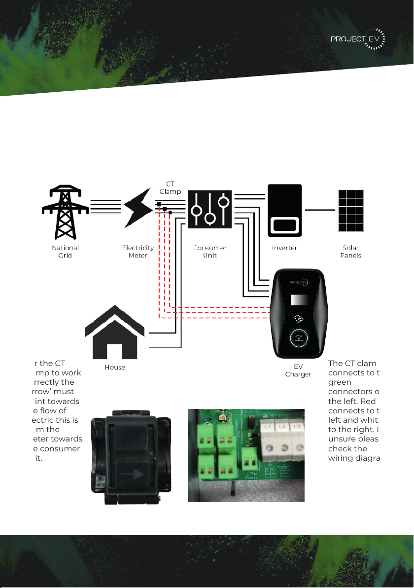
To monitor the real-time power import and export, a CT clamp is needed for this function
to work properly. The CT Clamp is needed to operate and use, both solar and dynamic load
balancing only.
Note: CT Clamp wiring can be extended up to 50m using Cat5e cable.
The CT clamp
connects to the
green
connectors on
the left. Red
connects to the
left and white
to the right. If
unsure please
check the
wiring diagram
on the PCB
underneath
connections L1
and L2.
For the CT
clamp to work
correctly the
‘Arrow’ must
point towards
the flow of
electric this is
from the
meter towards
the consumer
unit.
12
5LJKWFOLFNRQ/RFDO$UHD&RQQHFWLRQDQGFOLFNRQ3URSHUWLHV
6HOHFW,QWHUQHW3URWRFRO9HUVLRQ7&3,3YDQGFOLFNRQ3URSHUWLHV
6HOHFW8VHWKHIROORZLQJ,3DGGUHVVDQGHQWHUWKH,3DGGUHVV6XEQHW0DVN'HIDXOW
*DWHZD\&OLFN2.DQGFORVHWKH/RFDO$UHD&RQQHFWLRQSURSHUWLHVZLQGRZ
F &KHFN ZKDW ZHE EURZVHU LV EHLQJ XVHG LW¶V VXJJHVWHG WR XVH )LUHIR[ RU ,( &KURPH
FDQQRWEHXVHGWRXSGDWHILUPZDUH
G &KHFNLI\RXKDYH LQSXWWKHFRPSOHWHFRQWHQWZKLFKLVKWWSLQWKH
DGGUHVVILHOGGRQRWOHDYHRXWWKHKWWSRUWKH³´
H 6RPHWLPHV\RXPD\QHHGWRUHVWDUWWKHFKDUJHUWRDFFHVVLWVSDUDPHWHUVHWWLQJSDJH
I ,I \RX KDYH FKDQJHG WKH FKDUJHU¶V ,3 WR RWKHU YDOXH DQG FDQQRW UHPHPEHU \RX FDQ
UHVWRUHWKHFKDUJHUWRIDFWRU\VHWWLQJE\ORQJSUHVVWKHUHVHWEXWWRQ7KHQ\RXFDQDFFHVV
LWXVLQJKWWS
3OHDVHQRWH$IWHUUHVWRULQJWKHFKDUJHUWRIDFWRU\VHWWLQJ\RX¶OOQHHGWRUHVHWWKHFKDUJHU
,'DQGVHUYHUXUORWKHUZLVHWKHFKDUJHUZRQ¶WEHFRQQHFWHGWRWKHEDFNRIILFHVHUYHU
5HVHWEXWWRQ
(3). Right-click on Local Area Connection and click on Properties.
(4). Select Internet Protocol Version 4 (TCP/IPv4) and click on Properties.
(5). Select “Use the following IP address” and enter the IP address, Subnet Mask,
Default Gateway. Click OK and close the Local Area Connection properties window.
c. Check which web browser is being used, it’s suggested you use Firefox or IE.
Chrome cannot be used to update rmware.
d. Check if you have input the complete path, which is http://192.168.1.5:8080, in the
address eld, do not leave out the http:// or the“:8080”.
e. You may need to restart the charger to access its parameter setting page.
f. If you have changed the charger’s IP to another value but cannot remember it, you
can restore the charger to factory setting by pressing and holding the reset button.
Then you can access it using http://192.168.1.5:8080.
Please note: After restoring the charger to factory setting, you need to reset the
charger ID and server url, or the charger won’t be connected to the back-oce server.
32 33

3XWWKHFKDUJHSRLQWRQWRWKHEUDFNHWDQGIL[LWZLWKWKHVFUHZVDWWKHERWWRPRI
WKHFKDUJHSRLQW7KHLQVWDOODWLRQLVGRQH
&ULPSWKHEHORZVKRZQLQVXODWHGIHUUXOHRUULQJWHUPLQDOVRQWKHHQGRIWKH$&LQSXW
ZLUHV&RQQHFWWKHZLUHVLQWRWKHWHUPLQDOEORFNRIWKHFKDUJHSRLQWDVEHORZ&KHFNWKH
ZLULQJDQGWKHQFORVHWKH5&'LQWKHVLGHZLQGRZ&ORVHWKHVLGHZLQGRZZLWKWKHFRYHU
WKHQWKHZULQJLVGRQH
0RXQWRQDSROH
2SHQWKHSDFNDJLQJRIWKHSROHWDNHRXWWKHSROHDQGPRXQWLQJDFFHVVRULHV
7KHSROHPXVWEHLQVWDOOHGRQDKDUGVXUIDFHFRQFUHWHVXUIDFHLVUHFRPPHQGHGLW
FDQDOVREHPRXQWHGRQDVROLGJURXQG'ULOOKROHVDFFRUGLQJWRWKHUHTXLUHPHQWVPDUNHG
RQWKHLOOXVWUDWLRQIRUIL[LQJH[SDQVLRQEROWV
)L[WKHSROHRQWRWKHKROHVZLWKH[SDQVLRQEROWV7KHLQSXWFDEOHVVKDOOJRLQWRWKH
SROH IURP WKH ERWWRP PLGGOH DUHD DQG FRPH RXW RI LW IURP WKH DUHD EHORZ WKH FDEOH
KRRNHU
3.1.3 Put the charge point onto the bracket, and x it with the 2 screws at the bottom of
the charge point. The installation is done.
3.1.4 Crimp the insulated ferrule or ring terminals on the end of the AC input wires.
Connect the wires into the terminal block of the charge point as below. Check the
wiring and then close the RCD in the side window. Close the side window with the
cover, then the wiring is completed.
3.2.2 The pole must be installed on a hard surface, concrete surface is recommended,
it can also be mounted on a solid ground. Drill holes according to the requirements
marked on the illustration for xing expansion bolts.
3.2.3 Fix the pole onto the holes with expansion bolts. The input cables shall go
into the pole from the bottom middle area and come out of it from the area below the
cable hooker.
3.2 Mount on a pole
3.2.1 Open the packaging of the pole, take out the pole and mounting accessories.
8 9
13
Load Management
22KW
Dynamic Load Management
For dynamic load management to work the CT clamp must be installed correctly and the
following setting must be set:
- Enable Power Allocation - Enabled
- External current sampling method - CT2000
- External monitored max input power (kw) - main fuse size
External monitored max input power is measured in kw and must be set to the main fuse
size so that if the load on the property was to reach the limit set the charger would reduce
it’s output accordingly to not exceed the property main fuse.
60A = 13kw
80A = 18kw
100A = 23kw
Static Load Management
For installations where dynamic load management is not possible you can hard limit the
charger using setting ‘charger maximum output current (A)’ - As default this will be 32A
(7.3kw) however can be downrated to as low as 6A (1.76kw) if required and anything
inbetween.
5LJKWFOLFNRQ/RFDO$UHD&RQQHFWLRQDQGFOLFNRQ3URSHUWLHV
6HOHFW,QWHUQHW3URWRFRO9HUVLRQ7&3,3YDQGFOLFNRQ3URSHUWLHV
6HOHFW8VHWKHIROORZLQJ,3DGGUHVVDQGHQWHUWKH,3DGGUHVV6XEQHW0DVN'HIDXOW
*DWHZD\&OLFN2.DQGFORVHWKH/RFDO$UHD&RQQHFWLRQSURSHUWLHVZLQGRZ
F &KHFN ZKDW ZHE EURZVHU LV EHLQJ XVHG LW¶V VXJJHVWHG WR XVH )LUHIR[ RU ,( &KURPH
FDQQRWEHXVHGWRXSGDWHILUPZDUH
G &KHFNLI\RXKDYH LQSXWWKHFRPSOHWHFRQWHQWZKLFKLVKWWSLQWKH
DGGUHVVILHOGGRQRWOHDYHRXWWKHKWWSRUWKH³´
H 6RPHWLPHV\RXPD\QHHGWRUHVWDUWWKHFKDUJHUWRDFFHVVLWVSDUDPHWHUVHWWLQJSDJH
I ,I \RX KDYH FKDQJHG WKH FKDUJHU¶V ,3 WR RWKHU YDOXH DQG FDQQRW UHPHPEHU \RX FDQ
UHVWRUHWKHFKDUJHUWRIDFWRU\VHWWLQJE\ORQJSUHVVWKHUHVHWEXWWRQ7KHQ\RXFDQDFFHVV
LWXVLQJKWWS
3OHDVHQRWH$IWHUUHVWRULQJWKHFKDUJHUWRIDFWRU\VHWWLQJ\RX¶OOQHHGWRUHVHWWKHFKDUJHU
,'DQGVHUYHUXUORWKHUZLVHWKHFKDUJHUZRQ¶WEHFRQQHFWHGWRWKHEDFNRIILFHVHUYHU
5HVHWEXWWRQ
(3). Right-click on Local Area Connection and click on Properties.
(4). Select Internet Protocol Version 4 (TCP/IPv4) and click on Properties.
(5). Select “Use the following IP address” and enter the IP address, Subnet Mask,
Default Gateway. Click OK and close the Local Area Connection properties window.
c. Check which web browser is being used, it’s suggested you use Firefox or IE.
Chrome cannot be used to update rmware.
d. Check if you have input the complete path, which is http://192.168.1.5:8080, in the
address eld, do not leave out the http:// or the“:8080”.
e. You may need to restart the charger to access its parameter setting page.
f. If you have changed the charger’s IP to another value but cannot remember it, you
can restore the charger to factory setting by pressing and holding the reset button.
Then you can access it using http://192.168.1.5:8080.
Please note: After restoring the charger to factory setting, you need to reset the
charger ID and server url, or the charger won’t be connected to the back-oce server.
32 33
3XWWKHFKDUJHSRLQWRQWRWKHEUDFNHWDQGIL[LWZLWKWKHVFUHZVDWWKHERWWRPRI
WKHFKDUJHSRLQW7KHLQVWDOODWLRQLVGRQH
&ULPSWKHEHORZVKRZQLQVXODWHGIHUUXOHRUULQJWHUPLQDOVRQWKHHQGRIWKH$&LQSXW
ZLUHV&RQQHFWWKHZLUHVLQWRWKHWHUPLQDOEORFNRIWKHFKDUJHSRLQWDVEHORZ&KHFNWKH
ZLULQJDQGWKHQFORVHWKH5&'LQWKHVLGHZLQGRZ&ORVHWKHVLGHZLQGRZZLWKWKHFRYHU
WKHQWKHZULQJLVGRQH
0RXQWRQDSROH
2SHQWKHSDFNDJLQJRIWKHSROHWDNHRXWWKHSROHDQGPRXQWLQJDFFHVVRULHV
7KHSROHPXVWEHLQVWDOOHGRQDKDUGVXUIDFHFRQFUHWHVXUIDFHLVUHFRPPHQGHGLW
FDQDOVREHPRXQWHGRQDVROLGJURXQG'ULOOKROHVDFFRUGLQJWRWKHUHTXLUHPHQWVPDUNHG
RQWKHLOOXVWUDWLRQIRUIL[LQJH[SDQVLRQEROWV
)L[WKHSROHRQWRWKHKROHVZLWKH[SDQVLRQEROWV7KHLQSXWFDEOHVVKDOOJRLQWRWKH
SROH IURP WKH ERWWRP PLGGOH DUHD DQG FRPH RXW RI LW IURP WKH DUHD EHORZ WKH FDEOH
KRRNHU
3.1.3 Put the charge point onto the bracket, and x it with the 2 screws at the bottom of
the charge point. The installation is done.
3.1.4 Crimp the insulated ferrule or ring terminals on the end of the AC input wires.
Connect the wires into the terminal block of the charge point as below. Check the
wiring and then close the RCD in the side window. Close the side window with the
cover, then the wiring is completed.
3.2.2 The pole must be installed on a hard surface, concrete surface is recommended,
it can also be mounted on a solid ground. Drill holes according to the requirements
marked on the illustration for xing expansion bolts.
3.2.3 Fix the pole onto the holes with expansion bolts. The input cables shall go
into the pole from the bottom middle area and come out of it from the area below the
cable hooker.
3.2 Mount on a pole
3.2.1 Open the packaging of the pole, take out the pole and mounting accessories.
8 9
14
Installation
Modbus Meter
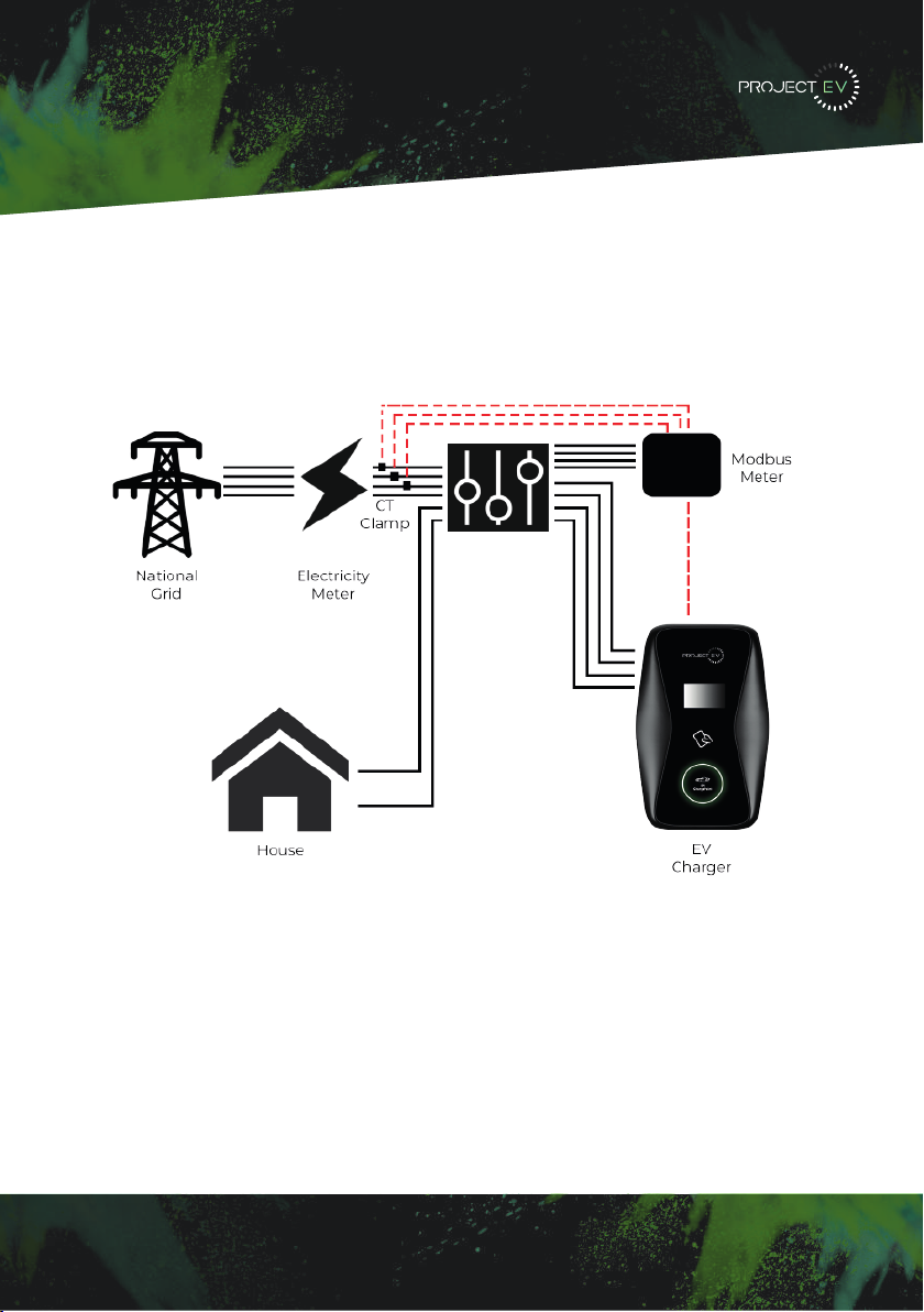
To monitor the real-time power import and export, a CT clamp is needed for this function
to work properly. The CT Clamp is needed to operate and use, both solar and dynamic load
balancing only.
Note: CT Clamp wiring can be extended up to 50m using Cat5e cable.
G 6RPH URXWHUV KDYH :L)L RQH LV *+] WKH RWKHU LV *+] 0RVW KRPHV MXVW XVH WKH
*+]:L)LDVWKHLUGHIDXOW:L)L%XWWKHFKDUJHUFDQRQO\FRQQHFWWRWKH*+]:L)L6RLI
WKH FKDUJHU FDQ FRQQHFW WR \RXU PRELOH SKRQH KRWVSRW EXW FDQQRW FRQQHFW WR WKH KRPH
:L)L3OHDVHFKHFNZLWKWKHKRPHRZQHURUFKHFNRQWKHLUURXWHUWRVHHLI\RXDUHXVLQJWKH
*+]:L)L3OHDVHGRXVHWKH*+]:L)LIRUFKDUJHUFRQQHFWLRQ
H &KHFNLI WKH FKDUJHU LVVWLOOFRQQHFWHG WR WKH FRPSXWHU 3OHDVH XQSOXJLWIURP FRPSXWHU
RWKHUZLVHWKHFKDUJHUZRQªWFRQQHFWWRWKHEDFNRIILFHVHUYHU
I &KHFN LI VHUYHU DGGUHVV LV FRUUHFW LQ WKH§6HUYHU 85/¨ ILHOG 7KH FRUUHFW VHWWLQJ LV
ZVFKDUJHJURZDWWFRPRFSSZV
&DQQRWDFFHVVSDUDPHWHUVHWWLQJSDJH
&OLFN 6WDUW 0HQX!&RQWURO 3DQHO!1HWZRUN DQG 6KDULQJ &HQWHU )RU :LQGRZV DQG
KLJKHUVHDUFKIRUDQGRSHQ&RQWURO3DQHODQGVHOHFW1HWZRUNDQG,QWHUQHW
7RVHWDVWDWLF,3RQ\RXU:LQGRZVFRPSXWHU
A &KHFNLI\RXKDYHFRQQHFWHGWKHFKDUJHUWR\RXUFRPSXWHU
B &KHFNLI\RXKDYHFKDQJHWKHFRPSXWHUªV,3WR[[FDQEHDQ\YDOXHEHWZHHQ
DQGH[FHSW
&OLFN&KDQJHDGDSWHUVHWWLQJV
d. Some routers have 2 WiFi signals, one is 2.4GHz, the other is 5GHz. Most homes
use the 5GHz WiFi as their default WiFi but the charger can only connect to the 2.4GHz
WiFi. So if the charger can connect to your mobile phone hotspot, but cannot connect
to the home WiFi please check the router to see if you are using the 5GHz WiFi. Use the
2.4GHz WiFi for charger connection.
e. Check if the charger is still connected to the computer. Please unplug it from
computer otherwise the charger won’t connect to the back-oce server.
f. Check if server address is correct in the“Server URL” eld. The correct setting is :
ws://ess-charge.atesspower.com:80/ocpp/ws
7.4 Cannot access parameter setting page
a. Check if you have connected the charger to your computer,
b. Check if you have changed the computer’s IP to 192.168.1.x (x can be any value
between 1 and 255 except 5).
To set a static IP on your Windows computer:
(1). Click Start Menu>Control Panel>Network and Sharing Center. (For Windows 8 and
higher, search for and open Control Panel and select Network and Internet).
(2). Click Change adapter settings.
30 31
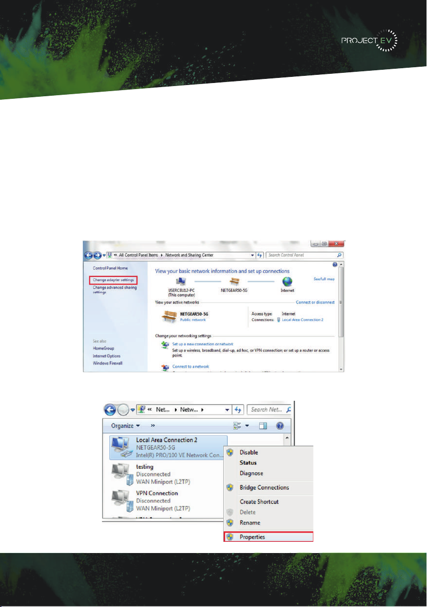
Setting the laptop for a static IP.
The Charger’s default IP address is 192.168.1.5. To access the parameter setting interface,
you’ll need to first set the computer’s IP to 192.168.1.3
To set a static IP on your Windows computer:
1. Click Start Menu > Control Panel > Network and Sharing Center. (For Windows 8 and
higher, search for and open Control Panel and select Network and Internet).
2. Click Change adapter settings.
3. Right-click on Local Area Connection Ethernet and click on properties.
G 6RPH URXWHUV KDYH :L)L RQH LV *+] WKH RWKHU LV *+] 0RVW KRPHV MXVW XVH WKH
*+]:L)LDVWKHLUGHIDXOW:L)L%XWWKHFKDUJHUFDQRQO\FRQQHFWWRWKH*+]:L)L6RLI
WKH FKDUJHU FDQ FRQQHFW WR \RXU PRELOH SKRQH KRWVSRW EXW FDQQRW FRQQHFW WR WKH KRPH
:L)L3OHDVHFKHFNZLWKWKHKRPHRZQHURUFKHFNRQWKHLUURXWHUWRVHHLI\RXDUHXVLQJWKH
*+]:L)L3OHDVHGRXVHWKH*+]:L)LIRUFKDUJHUFRQQHFWLRQ
H &KHFNLI WKH FKDUJHU LVVWLOOFRQQHFWHG WR WKH FRPSXWHU 3OHDVH XQSOXJLWIURP FRPSXWHU
RWKHUZLVHWKHFKDUJHUZRQªWFRQQHFWWRWKHEDFNRIILFHVHUYHU
I &KHFN LI VHUYHU DGGUHVV LV FRUUHFW LQ WKH§6HUYHU 85/¨ ILHOG 7KH FRUUHFW VHWWLQJ LV
ZVFKDUJHJURZDWWFRPRFSSZV
&DQQRWDFFHVVSDUDPHWHUVHWWLQJSDJH
&OLFN 6WDUW 0HQX!&RQWURO 3DQHO!1HWZRUN DQG 6KDULQJ &HQWHU )RU :LQGRZV DQG
KLJKHUVHDUFKIRUDQGRSHQ&RQWURO3DQHODQGVHOHFW1HWZRUNDQG,QWHUQHW
7RVHWDVWDWLF,3RQ\RXU:LQGRZVFRPSXWHU
A &KHFNLI\RXKDYHFRQQHFWHGWKHFKDUJHUWR\RXUFRPSXWHU
B &KHFNLI\RXKDYHFKDQJHWKHFRPSXWHUªV,3WR[[FDQEHDQ\YDOXHEHWZHHQ
DQGH[FHSW
&OLFN&KDQJHDGDSWHUVHWWLQJV
d. Some routers have 2 WiFi signals, one is 2.4GHz, the other is 5GHz. Most homes
use the 5GHz WiFi as their default WiFi but the charger can only connect to the 2.4GHz
WiFi. So if the charger can connect to your mobile phone hotspot, but cannot connect
to the home WiFi please check the router to see if you are using the 5GHz WiFi. Use the
2.4GHz WiFi for charger connection.
e. Check if the charger is still connected to the computer. Please unplug it from
computer otherwise the charger won’t connect to the back-oce server.
f. Check if server address is correct in the“Server URL” eld. The correct setting is :
ws://ess-charge.atesspower.com:80/ocpp/ws
7.4 Cannot access parameter setting page
a. Check if you have connected the charger to your computer,
b. Check if you have changed the computer’s IP to 192.168.1.x (x can be any value
between 1 and 255 except 5).
To set a static IP on your Windows computer:
(1). Click Start Menu>Control Panel>Network and Sharing Center. (For Windows 8 and
higher, search for and open Control Panel and select Network and Internet).
(2). Click Change adapter settings.
30 31
5LJKWFOLFNRQ/RFDO$UHD&RQQHFWLRQDQGFOLFNRQ3URSHUWLHV
6HOHFW,QWHUQHW3URWRFRO9HUVLRQ7&3,3YDQGFOLFNRQ3URSHUWLHV
6HOHFW8VHWKHIROORZLQJ,3DGGUHVVDQGHQWHUWKH,3DGGUHVV6XEQHW0DVN'HIDXOW
*DWHZD\&OLFN2.DQGFORVHWKH/RFDO$UHD&RQQHFWLRQSURSHUWLHVZLQGRZ
F &KHFN ZKDW ZHE EURZVHU LV EHLQJ XVHG LW¶V VXJJHVWHG WR XVH )LUHIR[ RU ,( &KURPH
FDQQRWEHXVHGWRXSGDWHILUPZDUH
G &KHFNLI \RXKDYHLQSXWWKHFRPSOHWH FRQWHQWZKLFKLVKWWSLQ WKH
DGGUHVVILHOGGRQRWOHDYHRXWWKHKWWSRUWKH³´
H 6RPHWLPHV\RXPD\QHHGWRUHVWDUWWKHFKDUJHUWRDFFHVVLWVSDUDPHWHUVHWWLQJSDJH
I ,I \RX KDYH FKDQJHG WKH FKDUJHU¶V ,3 WR RWKHU YDOXH DQG FDQQRW UHPHPEHU \RX FDQ
UHVWRUHWKHFKDUJHUWRIDFWRU\VHWWLQJE\ORQJSUHVVWKHUHVHWEXWWRQ7KHQ\RXFDQDFFHVV
LWXVLQJKWWS
3OHDVHQRWH$IWHUUHVWRULQJWKHFKDUJHUWRIDFWRU\VHWWLQJ\RX¶OOQHHGWRUHVHWWKHFKDUJHU
,'DQGVHUYHUXUORWKHUZLVHWKHFKDUJHUZRQ¶WEHFRQQHFWHGWRWKHEDFNRIILFHVHUYHU
5HVHWEXWWRQ
(3). Right-click on Local Area Connection and click on Properties.
(4). Select Internet Protocol Version 4 (TCP/IPv4) and click on Properties.
(5). Select “Use the following IP address” and enter the IP address, Subnet Mask,
Default Gateway. Click OK and close the Local Area Connection properties window.
c. Check which web browser is being used, it’s suggested you use Firefox or IE.
Chrome cannot be used to update rmware.
d. Check if you have input the complete path, which is http://192.168.1.5:8080, in the
address eld, do not leave out the http:// or the“:8080”.
e. You may need to restart the charger to access its parameter setting page.
f. If you have changed the charger’s IP to another value but cannot remember it, you
can restore the charger to factory setting by pressing and holding the reset button.
Then you can access it using http://192.168.1.5:8080.
Please note: After restoring the charger to factory setting, you need to reset the
charger ID and server url, or the charger won’t be connected to the back-oce server.
32 33
Configuring a laptop
for commissioning
15

4. Select Internet Protocol Version 4 (TCP/IPV4) and click on properties.
5. Select ‘Use the following IP address’ and enter the IP address, subnet mask, default
gateway. Click OK and close the Local Area Connection properties window.
5LJKWFOLFNRQ/RFDO$UHD&RQQHFWLRQDQGFOLFNRQ3URSHUWLHV
6HOHFW,QWHUQHW3URWRFRO9HUVLRQ7&3,3YDQGFOLFNRQ3URSHUWLHV
6HOHFW8VHWKHIROORZLQJ,3DGGUHVVDQGHQWHUWKH,3DGGUHVV6XEQHW0DVN'HIDXOW
*DWHZD\&OLFN2.DQGFORVHWKH/RFDO$UHD&RQQHFWLRQSURSHUWLHVZLQGRZ
F &KHFN ZKDW ZHE EURZVHU LV EHLQJ XVHG LW¶V VXJJHVWHG WR XVH )LUHIR[ RU ,( &KURPH
FDQQRWEHXVHGWRXSGDWHILUPZDUH
G &KHFNLI\RXKDYH LQSXWWKHFRPSOHWHFRQWHQWZKLFKLVKWWSLQWKH
DGGUHVVILHOGGRQRWOHDYHRXWWKHKWWSRUWKH³´
H 6RPHWLPHV\RXPD\QHHGWRUHVWDUWWKHFKDUJHUWRDFFHVVLWVSDUDPHWHUVHWWLQJSDJH
I ,I \RX KDYH FKDQJHG WKH FKDUJHU¶V ,3 WR RWKHU YDOXH DQG FDQQRW UHPHPEHU \RX FDQ
UHVWRUHWKHFKDUJHUWRIDFWRU\VHWWLQJE\ORQJSUHVVWKHUHVHWEXWWRQ7KHQ\RXFDQDFFHVV
LWXVLQJKWWS
3OHDVHQRWH$IWHUUHVWRULQJWKHFKDUJHUWRIDFWRU\VHWWLQJ\RX¶OOQHHGWRUHVHWWKHFKDUJHU
,'DQGVHUYHUXUORWKHUZLVHWKHFKDUJHUZRQ¶WEHFRQQHFWHGWRWKHEDFNRIILFHVHUYHU
5HVHWEXWWRQ
(3). Right-click on Local Area Connection and click on Properties.
(4). Select Internet Protocol Version 4 (TCP/IPv4) and click on Properties.
(5). Select “Use the following IP address” and enter the IP address, Subnet Mask,
Default Gateway. Click OK and close the Local Area Connection properties window.
c. Check which web browser is being used, it’s suggested you use Firefox or IE.
Chrome cannot be used to update rmware.
d. Check if you have input the complete path, which is http://192.168.1.5:8080, in the
address eld, do not leave out the http:// or the“:8080”.
e. You may need to restart the charger to access its parameter setting page.
f. If you have changed the charger’s IP to another value but cannot remember it, you
can restore the charger to factory setting by pressing and holding the reset button.
Then you can access it using http://192.168.1.5:8080.
Please note: After restoring the charger to factory setting, you need to reset the
charger ID and server url, or the charger won’t be connected to the back-oce server.
32 33
Configuring a laptop
for commissioning
16

5LJKWFOLFNRQ/RFDO$UHD&RQQHFWLRQDQGFOLFNRQ3URSHUWLHV
6HOHFW,QWHUQHW3URWRFRO9HUVLRQ7&3,3YDQGFOLFNRQ3URSHUWLHV
6HOHFW8VHWKHIROORZLQJ,3DGGUHVVDQGHQWHUWKH,3DGGUHVV6XEQHW0DVN'HIDXOW
*DWHZD\&OLFN2.DQGFORVHWKH/RFDO$UHD&RQQHFWLRQSURSHUWLHVZLQGRZ
F &KHFN ZKDW ZHE EURZVHU LV EHLQJ XVHG LW¶V VXJJHVWHG WR XVH )LUHIR[ RU ,( &KURPH
FDQQRWEHXVHGWRXSGDWHILUPZDUH
G &KHFNLI\RXKDYH LQSXWWKHFRPSOHWHFRQWHQWZKLFKLVKWWSLQWKH
DGGUHVVILHOGGRQRWOHDYHRXWWKHKWWSRUWKH³´
H 6RPHWLPHV\RXPD\QHHGWRUHVWDUWWKHFKDUJHUWRDFFHVVLWVSDUDPHWHUVHWWLQJSDJH
I ,I \RX KDYH FKDQJHG WKH FKDUJHU¶V ,3 WR RWKHU YDOXH DQG FDQQRW UHPHPEHU \RX FDQ
UHVWRUHWKHFKDUJHUWRIDFWRU\VHWWLQJE\ORQJSUHVVWKHUHVHWEXWWRQ7KHQ\RXFDQDFFHVV
LWXVLQJKWWS
3OHDVHQRWH$IWHUUHVWRULQJWKHFKDUJHUWRIDFWRU\VHWWLQJ\RX¶OOQHHGWRUHVHWWKHFKDUJHU
,'DQGVHUYHUXUORWKHUZLVHWKHFKDUJHUZRQ¶WEHFRQQHFWHGWRWKHEDFNRIILFHVHUYHU
5HVHWEXWWRQ
(3). Right-click on Local Area Connection and click on Properties.
(4). Select Internet Protocol Version 4 (TCP/IPv4) and click on Properties.
(5). Select “Use the following IP address” and enter the IP address, Subnet Mask,
Default Gateway. Click OK and close the Local Area Connection properties window.
c. Check which web browser is being used, it’s suggested you use Firefox or IE.
Chrome cannot be used to update rmware.
d. Check if you have input the complete path, which is http://192.168.1.5:8080, in the
address eld, do not leave out the http:// or the“:8080”.
e. You may need to restart the charger to access its parameter setting page.
f. If you have changed the charger’s IP to another value but cannot remember it, you
can restore the charger to factory setting by pressing and holding the reset button.
Then you can access it using http://192.168.1.5:8080.
Please note: After restoring the charger to factory setting, you need to reset the
charger ID and server url, or the charger won’t be connected to the back-oce server.
32 33
Laptop commissioning
settings explained
Connect the charger to a computer via a network cable. Open the web browser and type
in 192.168.1.5:8080 in the address field and click enter, then the parameter setting page of
the charger will open up.
Parameter setting can only be done via web browser on a computer. It is suggested to use
microsoft edge or chrome (other browser might have compatibility problems).
1
2
3
4
5
6
7
8
9
10
11
12
13
14
15
16
17
18
19
20
21
22
23
24
25
26
27
28
29
30
31
32
33
34
35
36
37
38
39
40
41
42
43
44
45
46
47
48
49
50
51
52
53
17

1. Firmware version of the Charger. This item cannot be modified here on the setting page.
2. Charger ID: this is the unique identification of the Charger. If the charger is to be
connected to Project EV back-office server, this ID must be set as the serial number on the
nameplate of the Charger. Otherwise the Charger cannot be registered on the server.
3. Charger IP: The default IP is 192.168.1.5. It is not suggested to change the default IP. If you
have changed the default IP and forgot the new IP, you can reset the charger to factory
setting by long press the reset button(the reset button on control board, not the emergency
stop button) until the charger reboot. Then you can use the default 192.168.1.5 for access.
Please note: ID(same as serial number, can be found on the nameplate sticker) and server
url, otherwise the charger won’t be connected to the back-office server. After restoring the
charger to factory setting, you’ll need to reset the charger
4. Charger Subnet mask: The default value is 255.255.255.0. It is not suggested to change. If
the subnet mask has been reset to other value and you have forgotten the new value, you
can restore the charger to factory setting by long press the reset button.
5. Net MAC Address
6. Change the charger from static IP to DHCP- It is recommended to use static to allow
future access if required.
7. RFID TAG Limit
8. WiFi SSID(wireless network name)
9. Server URL is to set the domain name or IP address of the back office server to be
connected. The domain name of Project EV is ws://projectevcharger.com:80/ocpp/ws. For
electric miles use ws://occpp.electricmiles.io/
10. Charger Internal Time - This is when the unit is online as the time is retrieved from the
server.
11. To be used to alter the time zones should the charger be installed outside GMT time zone.
12. Max Temperature the charger internals will reach before triggering a fault.
13. Meter value time in Seconds - The charger sends these to the server to be displayed in the
app.
Laptop commissioning
settings explained
18

5LJKWFOLFNRQ/RFDO$UHD&RQQHFWLRQDQGFOLFNRQ3URSHUWLHV
6HOHFW,QWHUQHW3URWRFRO9HUVLRQ7&3,3YDQGFOLFNRQ3URSHUWLHV
6HOHFW8VHWKHIROORZLQJ,3DGGUHVVDQGHQWHUWKH,3DGGUHVV6XEQHW0DVN'HIDXOW
*DWHZD\&OLFN2.DQGFORVHWKH/RFDO$UHD&RQQHFWLRQSURSHUWLHVZLQGRZ
F &KHFN ZKDW ZHE EURZVHU LV EHLQJ XVHG LW¶V VXJJHVWHG WR XVH )LUHIR[ RU ,( &KURPH
FDQQRWEHXVHGWRXSGDWHILUPZDUH
G &KHFNLI \RXKDYHLQSXWWKHFRPSOHWH FRQWHQWZKLFKLVKWWSLQ WKH
DGGUHVVILHOGGRQRWOHDYHRXWWKHKWWSRUWKH³´
H 6RPHWLPHV\RXPD\QHHGWRUHVWDUWWKHFKDUJHUWRDFFHVVLWVSDUDPHWHUVHWWLQJSDJH
I ,I \RX KDYH FKDQJHG WKH FKDUJHU¶V ,3 WR RWKHU YDOXH DQG FDQQRW UHPHPEHU \RX FDQ
UHVWRUHWKHFKDUJHUWRIDFWRU\VHWWLQJE\ORQJSUHVVWKHUHVHWEXWWRQ7KHQ\RXFDQDFFHVV
LWXVLQJKWWS
3OHDVHQRWH$IWHUUHVWRULQJWKHFKDUJHUWRIDFWRU\VHWWLQJ\RX¶OOQHHGWRUHVHWWKHFKDUJHU
,'DQGVHUYHUXUORWKHUZLVHWKHFKDUJHUZRQ¶WEHFRQQHFWHGWRWKHEDFNRIILFHVHUYHU
5HVHWEXWWRQ
(3). Right-click on Local Area Connection and click on Properties.
(4). Select Internet Protocol Version 4 (TCP/IPv4) and click on Properties.
(5). Select “Use the following IP address” and enter the IP address, Subnet Mask,
Default Gateway. Click OK and close the Local Area Connection properties window.
c. Check which web browser is being used, it’s suggested you use Firefox or IE.
Chrome cannot be used to update rmware.
d. Check if you have input the complete path, which is http://192.168.1.5:8080, in the
address eld, do not leave out the http:// or the“:8080”.
e. You may need to restart the charger to access its parameter setting page.
f. If you have changed the charger’s IP to another value but cannot remember it, you
can restore the charger to factory setting by pressing and holding the reset button.
Then you can access it using http://192.168.1.5:8080.
Please note: After restoring the charger to factory setting, you need to reset the
charger ID and server url, or the charger won’t be connected to the back-oce server.
32 33
14. Only Required with other brands of sim cards
15. If used in 4G this is required to let the charger know which sim server to connect to.
16. This is the login password for the or laptop on commissioning default is 12345678 and is
recommended to change this on commissioning.
17. RCD Calibration
18. Solar Modes
19. Enable Load Management / Solar Features
20. Property Main Fuse Size (kw)
21. Load Management Meter Model
22. Opt Out/ Opt In of the UK EVC regulations default charging hours plug + charge
23-27. UK EVC regulations 2021 charge allowed times
28. UK EVC regulations 2021 randomised delay to 600 seconds and can be changed by end user
29. Save settings
30. Language
31. Charger Module
32. LAN Connection default gateway
33. Charger DNS server
34. Static output of the charger
35. Charging Mode: 1. APP/RFID mode; 2. RFID Mode; 3. Plug & Charge Mode
36. RFID Default Pin
37. WIFI Password
38. Default charging cost for records for multi tariffs set up in the app.
39. Daylight saving start + end date
40. Plug + charge allowed charge window
41. Heartbeat signal sent to the server (time in seconds)
42. Password required by some sim cards that are not Project EV.
43. Time out (in seconds) for starting charge without plugging in a vehicle
44. Required for testing purposes only
45. Minimum export power required before the vehicle charge will engage (1.76kw/6amp)
46. Load Management reading hardware - CT/Power Meter
47. Opt Out / Opt In of the UK EVC regulations default charging hours plug and charge
48. Power Meter Address
49-53. Limit your charger to the adjacent times. 0 is default setting 34.
Laptop commissioning
settings explained
19
This manual suits for next models
3
Table of contents
Other Project EV Batteries Charger manuals

Project EV
Project EV EVA-07S-SE-C User manual

Project EV
Project EV EVA-07S User manual

Project EV
Project EV EVA-07D-SE-W User manual

Project EV
Project EV ATESS EVA-11S User manual

Project EV
Project EV Dual Wall Pro Earth User manual

Project EV
Project EV EVA-07S-S User manual

Project EV
Project EV APEX-7.3 User manual

Project EV
Project EV EVA-07D-SE-RFID User manual


