Deta Connect LINK User manual

Connect LINK
9701
Signal Booster
9702
Connect
Features
Start Here
Deta Connect Link allows the WiFi control of your devices
Install the Data Connect App on to your smart phone, tablet or
PC to enable remote access to your whole system (wherever
you have internet access)
Extend the range with the Signal Booster enabling control to
the grandest of properties.
Go online
Because we are always making updates and improvements to Deta Connect
products, we need to ensure that you have the most up to date instruction
guide. Please visit the link below to view the current manual.
www.detaconnect.co.uk
Quick reference instructions
Please refer to the online instruction guide BEFORE attempting installation. The
diagram on the following page provides a useful reference when installing and
setting up the product. Deta Connect is fully legal to install in your own home:
however, if in doubt always consult a qualified electrician/Plumber.
Connect Link
How do I get started?
Power the Deta Connect Link and connect it to your home WiFi router.
The following instructions below will explain how. The Deta Connect Link
will then set itself up automatically. Download the free ‘Deta Connect’
App and follow the in-App instructions.
What you need
A standard home WiFi router with a broadband connection, a WiFi
enabled device such as a smartphone, and some Deta Connect devices to
control are all that is required.
**************************************************************************
The Connect Link requires a wireless router with a permanent
internet connection in order to operate. You will also require a WiFi
enabled smartphone, tablet or PC.
1.Take the ethernet connector cable (supplied) and connect it to any
spare available LAN port on your wireless router. Connect the other end of
the cable to the Connect Link’s single port.
2. Plug in the power supply, and push the jack plug into the AC connection
on the back of the Connect Link. Turn on the power supply. The green LED
on the Connect Link will illuminate to
indicate that the Link has power and is ready to be set up from the
smartphone or Web App.
***************************************************************************
The LED indicators
The LED indicators are used to indicate the status of the Link and to
indicate if there is a problem. If there is a problem reported, it will usually
refer to an insecure cable connection or a server connection problem. If it
has been set up correctly, the App will display details of any specific
problem. See www.Detaconnect.co.uk/.house for support.
There are three states:
green, amber and red.
Steady Green: Status normal
Flashing Green: Transmitting
Flashing Green/Amber: Linking mode
Steady Red: Cannot contact server
Flashing Red: Cable / router problem
App Set-up
1. Download the Deta Connect App from the App Store or Google Play. It
should automatically install onto your device.
2. Select the App icon and enter the App.
3. Please follow the in-App instructions which will take you through the setup
procedure.
4. If you need extra help with setup, please refer to the Help section in the App
(you can find this by entering the App, pressing the ‘more’ tab on the menu bar
and selecting ‘Help’).
Web App
You can also control the Connect Link from the Connect Web App. This is a
more extensive platform very suited to setting up and viewing large installs. It
also allows you to access the Heating Planner, which provides more detailed
and convenient scheduling. This can be accessed at www.detaconnect.co.uk

Connect LINK
9701
Signal Booster
9702
Connect
Signal Booster
The Deta Connect Signal Booster extends the operating distance
between transmitting and receiving Deta Connect devices.
Fitting & Installation
1. Use a small flat headed screwdriver to take off the hook.
2. Use the screwdriver to open the battery compartment door by
removing the 8 screws.
3. Install 2 AA 1.5V Alkaline batteries (not included); the LED light
will come on for 1 sec. then go off, indicating that the device has
entered STANDBY mode.
4. Pair the signal booster with the transmitter (please refer to the
‘setup’ section below).
5. Close the battery compartment door and replace the screws.
6. Replace the hook.
7. The signal booster can be wall mounted or stood on a flat
surface.
Linking the Signal Booster
1. Press “LEARN” button (located inside the battery compartment); the
LED will blink and enter learn mode.
2. Press the ‘ON’ button on the transmitter that is to be linked.
3. The LED in the Signal Booster will blink twice (slowly) to confirm the
linking.
4. The signal booster has six available memory spaces at any one time:
repeat steps 2-4 to program the other remaining available memory
spaces.
NOTE: Learning mode lasts for 12 seconds, if no signal is received from
a remote handset during this time then the booster will automatically exit
learning mode without linking the device.
Un-Linking the Signal Booster
Removing a single device:
1. Press “LEARN” button; the LED will blink.
2. Press the ‘OFF’ button on the transmitter that is to be un-paired
3. The LED on the Signal Booster will blink twice (slower) to confirm the
device is un-linked.
Removing all devices:
1. Press and hold the ‘LEARN’ button until the LED blinks rapidly.
2. Release the ‘LEARN’ button.
3. Press the ‘LEARN’ button again; the LED will blink twice (slower) to
confirm that all devices are un-linked.
RF frequency: 433.92MHz
Battery operated: 2 x AA (1.5V) alkaline (not included)
IP 56
Voltage / Power (LINK)
12V 6W
Voltage / Power (signal Booster)
1.5V
Radio Frequency
433.92MHz / 868 MHz
Radio Frequency
433.92MHz
DETA Electrical Company Limited
Kingsway House, Laporte Way
Luton, Bedfordshire. LU4 8RJ UK
NPD0519v1 December 2015 MCINS5 Tel; +44 (0)1582 544 544 Technical Helpline: +44(0)1582 544 548
This manual suits for next models
3
Popular Extender manuals by other brands
Shinybow USA
Shinybow USA SB-6130R instruction manual
AV-Box
AV-Box TPUH503 user manual

GoMax Electronics
GoMax Electronics CV-57C user manual
Extron electronics
Extron electronics DTP HDMI 301 user guide
DVIGear
DVIGear WILDCAT DVI-7570 user guide
Stuart Turner
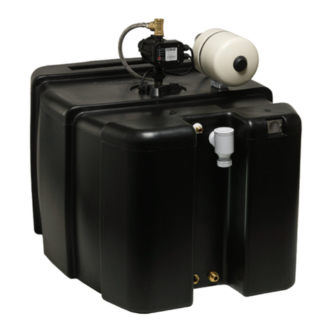
Stuart Turner MAINBOOST iTank MBI Series Installation, operation & maintenance instructions


