DETON MD Series User manual
jfDeETON
PROFESSIONAL SOUND SYSTEM
MD SERIAL
PROFESSIONAL
MIXERS
MD82/MD82A/MD122/MD122A
OWNER’S MANUAL
MD SERIES MIXERS ARE NEWLY DEVELOPED MIXERS. THEY ARE CONVIENT IN OPERATION AND
PERFECT IN FUNCTION. HIGH GAIN AND LOW NOISE MICROPHONE, DIGITAL SIGNAL
PROCESSOR(DSP)
AND100MM SLIP POTENTIOMETERCAN MEET ALL KINDS OF DEMANDS FROM
USERS.
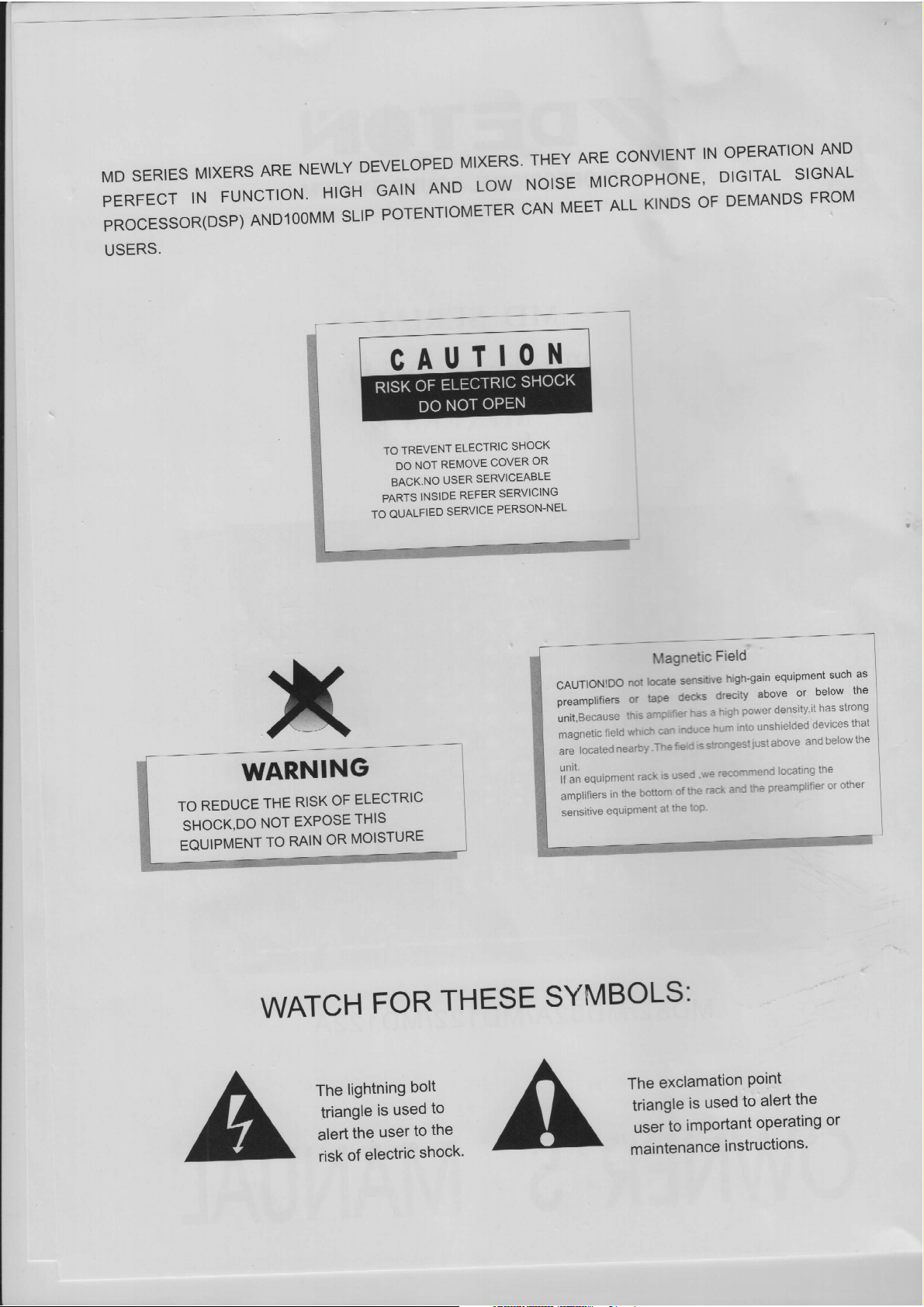
RISK OF ELECTRIC SHOCK
DO NOT OPEN
TO TREVENT ELECTRIC SHOCK
DO NOT REMOVE COVER OR
BACK.NO USER SERVICEABLE
PARTS INSIDE REFER SERVICING
TO QUALFIED SERVICE PERSON-NEL
Ee,
Magnetic Field |
CAUTIONIDO not locate sensitive high-gain equipment such as |
preamplifiers or tape decks drecity above oF below the |
unit,Because this amp fier has 2high power density,it has strong |
magnetic field whicn ca to unshielded devices that
are located nearby .The
fie sstrongest
just above and belowthe |
|
WARNING |
TO REDUCE THE RISK OF ELECTRIC
SHOCK,DO NOT EXPOSE THIS |
EQUIPMENT TO RAINOR MOISTURE |
TREE LSAT
unit.
if an equipment rack Is
US
amplifiers in the bottorr
WATCH FOR THESE SYMBOLS:
The lightning bolt
triangle is used to
alert the user to the
risk of electric shock.
The exclamation point
triangle is used to alert the
user to important operating or
maintenance instructions.
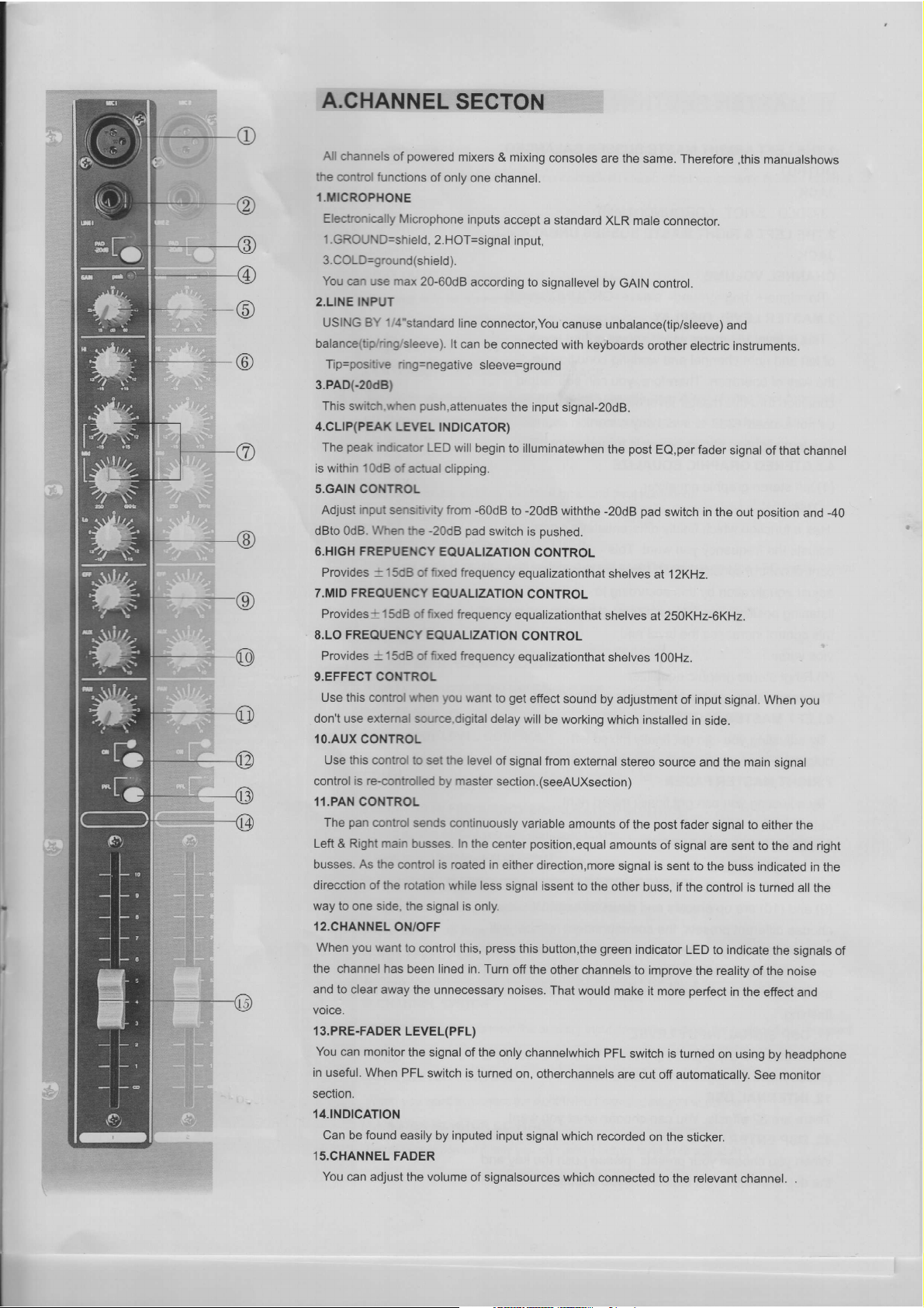
A.CHANNEL SECTON
All channels of powered mixers & mixing consoles are the same. Therefore ,this manualshows
the control functions of only one channel.
1.MICROPHONE
Electronically Microphone inputs accept astandard XLR male connector.
1.GROUND=shield, 2.HOT=signal input,
3.COLD=ground(shield).
You can use max 20-60dB according to signallevel by GAIN control.
2.LINE INPUT
USING BY 1/4"standard line connector, You
canuse unbalance(tip/sleeve) and
balance(tip/ring/sleeve). It can be connected with keyboards orother electric instruments.
Tip=positive ring=negative sleeve=ground
3.PAD(-20dB)
This switch.when push,attenuates the input signal-20dB.
4.CLIP(PEAK LEVEL INDICATOR)
The peak indicator LED will begin to illuminatewhen the post EQ,per fader signal of that channel
is within 10dB of actual clipping.
5.GAIN CONTROL
Adjust input sensitivity from -60dB to -20dB withthe -20dB pad switch in the out position and -40
dBto OdB. When the -20dB pad switch is pushed.
6.HIGH FREPUENCY EQUALIZATION CONTROL
Provides =15cB of fixed frequency equalizationthat shelves at 12KHz.
7.MID FREQUENCY EQUALIZATION CONTROL
Provides =15dB of fixed frequency equalizationthat shelves at 250KHz-6KHz.
8.LO FREQUENCY EQUALIZATION CONTROL
Provides +15dB of fixed frequency equalizationthat shelves 100Hz.
9.EFFECT CONTROL
Use this control when you want to get effect sound by adjustment of input signal. When you
don't use external source.digital delay will be working which installed in side.
10.AUX CONTROL
Use this contro! to set the level of signal from external stereo source and the main signal
control is re-controlled by master section.(seeAUXsection)
11.PAN CONTROL
The pan control sends continuously variable amounts of the post fader signal to either the
Left &Right main busses. In the center position,equal amounts of signal are sent to the and right
busses. As the control is roated in either direction,more
signal is sent to the buss indicated in the
direcction of the rotation while less signal issent to the other buss, if the control is turned all the
way to one side, the signal is only.
12.CHANNEL ON/OFF
When you want to control this, press this button,the green indicator LED to indicate the signals of
the channel has been lined in. Turn off the other channels to improve the reality of the noise
and to clear away the unnecessary noises. That would make it more perfect in the effect and
voice.
13.PRE-FADER LEVEL(PFL)
You can monitor the signal of the only channelwhich PFL switch is turned on using by headphone
in useful. When PFL switch is turned on, otherchannels are cut off automatically. See monitor
section.
14.INDICATION
Can be found easily by inputed input signal which recorded on the sticker.
15.CHANNEL FADER
You can adjust the volume of signalsources which connected to the relevant channel. .

B. MASTER SECTION
4.THE LEFT &RIGHT MASTE BUSSES BALANCED
OUTPUT
JACK.
3.COLD 2.HOT 1.GROUND(shield)
2.THE LEFT &RIGHT MASTE BUSSES UNBALANCE
JACK
CHANNEL VOLUME
Tip=signal+ ring=ground- sleeve=GROUND(shield)
3.MASTER LEVEL DISPLAY
This is level VU-meter which shows output levels
of left and right channel and working condition on
the way of operation. Therefore, you can see output
condition thru this master level display. Please
do not exceed +3dB to avoid any distortion sound.
The lamp lighting shows power is turned on or off.
4.5.STEREO GRAPHIC EQUALIZE
(4).left stereo graphic equalizer
This
Has afunction which finally differentiatesa signal and
adjusts the frequency you want. This
control control consists of left Channel band. You Can
adjust equalization by this according to
listening position and listener's taste.(Upper movement of
this control increases the level and
vice verse.)
(5).Rihgt stereo graphic equalizer
The same usage as the left graphic equlizer
6.LEFT MASTER FADER
By
adjusting,youcan get finally mixed left
output.
7.RIGHT MASTER FADER
By adjusting,you can get finally mixed right
output.
8. DSP DIGITAL INDICATOR
Indicating the effect which the dsp is working at.
9/10.DSP PRESETS
(9) and (10) are up presets and down presets. When you
choose different presets, the correspondent number will
change accordingly. When you push the presets, the led is
on but there is no effect output. Only you push enter key(13),
there is correspondent effect output and the led will stop
flashing.
41. DSP SIGNAL INPUT LEVEL
It indicates the dsp signal input level. When the red led is on,
please make the input level alittle smaller.
12. INTERNAL DSP
There are 32 effects. You can choose what you want.
13. DSP ENTER
When you choose your presets, please push the key and
the dsp is at the effect status that you choose.
Oo
©
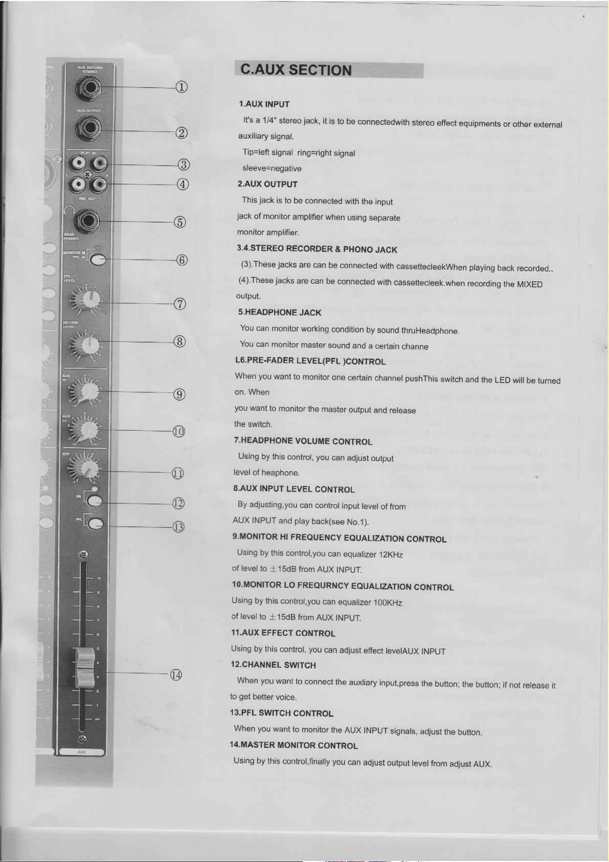
C.AUXSECT
1.AUX INPUT
It's a1/4" stereo jack, it is to be connectedwith stereo effect equipments or other external
auxiliary signal.
Tip=left signal ring=right signal
sleeve=negative
2.AUX OUTPUT
This jack is to be connected with the input
jack of monitor amplifier when using separate
monitor amplifier.
3.4.STEREO RECORDER &PHONO JACK
(3). These
jacks are can be connected with cassettecleekWhen playing back recorded..
(4).These
jacks are can be connected with cassettecleek.when recording the MIXED
output.
5.HEADPHONE JACK
You can monitor working condition by sound thruHeadphone.
You can monitor master sound and acertain channe
L6.PRE-FADER LEVEL(PFL )CONTROL
When you want to monitor one certain channel pushThis switch and the LED will be turned
on. When
you want to monitor the master output and release
the switch.
7.HEADPHONE VOLUME CONTROL
Using by this control, you can adjust output
level of heaphone.
8.AUX INPUT LEVEL CONTROL
By adjusting,you can control input level of from
AUX INPUT and play back(see No.1).
9.MONITOR HI FREQUENCY EQUALIZATION CONTROL
Using by this control,you can equalizer 12KHz
of level to +15dB from AUX INPUT.
10.MONITOR LO FREQURNCY EQUALIZATION CONTROL
Using by this control,you can equalizer 100KHz
of level to +15dB from AUX INPUT.
11.AUX EFFECT CONTROL
Using by this control, you can adjust effect levelAUX INPUT
12.CHANNEL SWITCH
When you want to connect the auxliary input,press the button; the button; if not release it
to get better voice.
13.PFL SWITCH CONTROL
When you want to monitor the AUX INPUT signals, adjust the button.
14.MASTER MONITOR CONTROL
Using by this control,finally you can adjust output level from adjust AUX.

D.EFFECT SECTION |
4/2. LEFT AND RIGHT AUX EFFECT RETURN
These are to be connected with other external processor.
3.TALKBACK MIC INPUT JACK
This jack can be used with amovable microphone
For the DJ.
1.GROUND=shield, 2.HOT=signal input.
3.COLD=ground(shield)
4.TALKBACK LEVEL CONTROL
You can set the level of the talkback being input
By adjusting the knob.
5.TALKBACK SIGNAL DISTRIBUTION CONTROL
When you want the signal to be distributed to the
Auxiliary channel,push AUX.When you want the signal to be
distributed to the
Effect channel, push EFF.
When you want the signal to be distributed to the
L/R channel, push L-R.
6. PHANTOM POWER SWITCH
When you use the microphone, push the button from the small hole
to switch on the +48v power. The led will be on.
7. LEFT MASTER LEVEL CONTROL
You can control the aux return level by adjusting the knob.
8. RIGHT MASTER LEVEL CONTROL
You can control the aux return level by adjusting the knob.
9.INPUT LEVEL CONTROL
Adjusting by this,you can control the level
being put into the digital DST.
10.PAN CONTROL
Using by this control, you can adjust echo
sound & external dffector sound between left &
right.
11.CHANNEL SWITCH CONTROL
If you want the effect,push the button then
the effect will enter the main channel, if not,
release it to get the better voice.
12.PFL SWITCH
If push this button, you can monitor the effect
Independently by headphone.
13.EFFECT FADER CONTROL
Using by this control,you adjust signal level& extermal effector.
€FFECT

“MODE
we MD82 MD82A MD122 MD122A
CONDITON
-60dBm~-40dBm -60dBm~-40dBm
-60dBm~-40dBm -60dBm~-40dBm
Input Sensitivty PAD ON: PAD ON: PAD ON: PAD ON:
-40dBm~-20dBm -40dBm~-20dBm -40dBm~-20dBm -40dBm~-20dBm
Mic-60dBm Mic-60dBm Mic-60dBm Mic-60dBm
Line-20dBm Line-20dBm Line-20dBm Line-20dBm
Nomins! Input Level Eff Ret -20dB Eff Ret -20dB Eff Ret -20dB Eff Ret -20dB
Aux In -20dB Aux In -20dB Aux In -20dB Aux In -20dB
Tape
In -10dB Tape
In -10dB Tape
In-10dB Tape
In-10dB
‘Eff Send -10dBm Eff
Send -10dBm Eff
Send -10dBm Eff Send -10dBm
Nomin! Output Level |4. Send OdBm Aux Send 0dBm Aux Send 0dBm Aux Send 0dBm
Common Mode
Rejectiah |-60dB -60dB -60dB -60dB
Output Voltage
(mixer Part) 4VMax |4VMax 4VMax 4VMax
S/N Ratio =70dB >=70dB >70dB >=70dB
THD(ikhz Full Power) |ess than 0.03%(at1KHz)Less
than 0.03%(at1KHz)|Lessthan0.03%(at
1KHz)
|Less than 0.03%(at1KHz)
20Hz-20KHz + 3dB 20Hz-20KHz + 3dB
Frequency Response =. 20Hz-20KHz + 3dB_~=——-
20Hz-20KHz + 3dB
Headphone 7V/220 27V/220 27V/220 27V/220 2
Hi+ 15dB/12KHz Hi-+ 15dB/12KHz Hi+ 15dB/12KHz Hi-- 15dB/12KHz
Mid +15dB Mid +15dB Mid +15dB Mid +15dB
Parametric CQ 250Hz-6KHz 250Hz-6KHz 250Hz-6KHz 250Hz-6KHz
Lo +15dB/80KHz Lo +15dB/80KHz Lo +15dB/80KHz Lo +15dB/80KHz
Output Power 2x 350W/4
Q2x 350W/4 Q
Power Conaumption 40W 900W 40W 900W
AC 220-240V,100-120V(option)/50-60Hz
Power Supply

lfDeETeON
PROFESSIONAL SOUND SYSTEM
This manual suits for next models
4
Table of contents
Popular Music Mixer manuals by other brands


LG-Ericsson
LG-Ericsson 1024idss Quick installation guide

Precision Flight Controls
Precision Flight Controls USB Throttle Quadrant Console Setup guide

Franklin Fueling Systems
Franklin Fueling Systems INCON S940 Installation and operation guide

Rolls
Rolls MX34c LiveMix quick start guide

Denon
Denon DNX500 - Pro DJ Mixer operating instructions

Crest Audio
Crest Audio V12 Specifications