English
TABLE
OF
CONTENTS
Location
of
parts
and
controls
..
...
..
.................
..
.........
...
.
...
..
............... 3
Features ...
...
..
..
...
..........................................................
...
...
................... 4
Precautions..............
..
........................
...
....
..
...
..
................
....
...
...
..
..
...
..
..
5
Operating voltage..
...
..
..
...........................................
...
............
..
.
..
.
..
....
..
5
Function
of
parts
and
controls
..
..
.
...
.
..
.
..
......
..
...
.........................
...
...
...
5
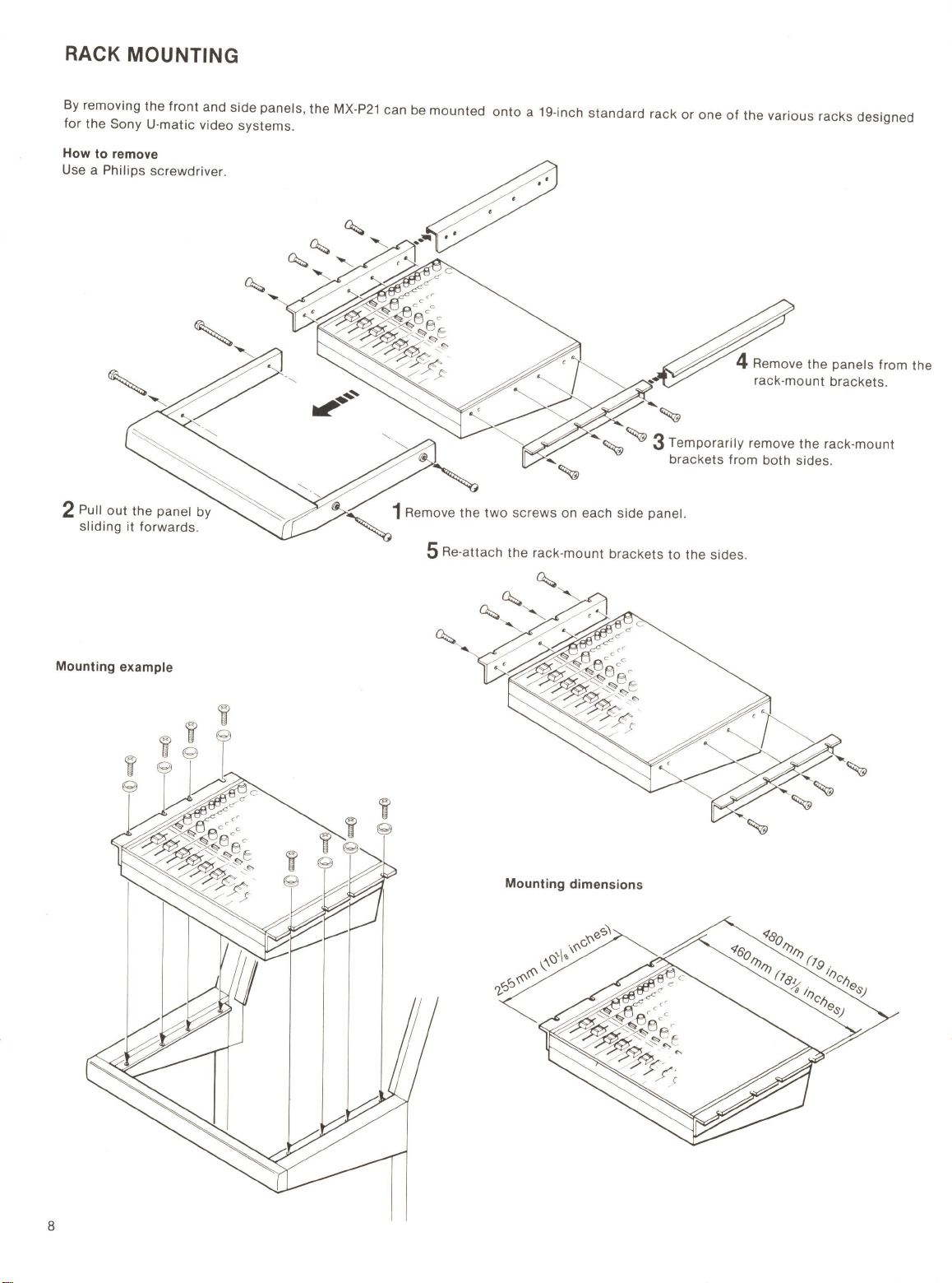
Rack
mounting
.
..
...
.
...
..
.......
..
.....................
..
..
..
...........
....
...
....
...
............ 8
Specifications
..
.
..
.....
...
..
..
...........................
..
.......
..
...
...........
...
.
...
.......... 9
Block
diagram
...........................
....
......................
..
..
..
...
.
...
.....................26
Operating curves
...
..
.....
..
....
.
...
.....
...
.........
..
.
...
...
..
..
....
.
...
..
...
....
.....
...
.......
26
4
FEATURES
The Sony MX-P21 has been designed
to
be
multi
-purpose audio mi
x-
er
capable
of
performing
all
the
essential
functions
required for a
public
address system, radio and
TV
broadcasting
,
studio
re
cord-
ing and tape
editing
.
8 channel inputs with various adjustment possibilities
Each
input
can be
independently
adjusted
to
suit
the connected
equipment
and
to
provide excellent mixing results from
its
own low-
cut
filter
and
equalization
circuits
. With the PAN
POT
(panoramic
potentiometer)
function
, each
input
sound image can be positioned
to
the
desired
spot
between the
Land
R stereo
output
channels.
Auxiliary inputs and outputs for additional mixing effects
By
connecting
an echo
machine
or
a reverberation
unit
, additional-
ly desired sound
effects
may be easily obtained.
One
of
the
outputs
can be used
to
supply signals
to
a fold-back
speaker
for
players on
the
stage.
Monitoring of various signals
Each line and aux
iliary
output
signal can
be
monitored either with
headphones
or
speakers
for
accurate
mixing.
In
addition
, the PFL
(pre-fader listening)
function
permits
direct
monitoring
of
each of
the
original
incoming
signals
.
Talk-back function indispensable for studio
use
The
built
-in
microphone
enables
the
operator
to
directly
communi-
cate
with
those
in
the
studio
.
Easy rack mounting
The
table
-
top
design can be
easily
converted for rack-mounting in a
19-inch
standard
rack or in
specified
racks designed for Sony
U-
matic
video
systems
.
2-way powering for the unit plus microphones
The built-in DC-DC converter enables
stable
operation from either a
12V
car
battery
or
an ac power
supply
,
or
both
. Furthermore, the
unit
can
supply
48 V de
to
each
of
the
connected phantom powered
condenser
microphones
.
Supplementary functions for full creative flexibility
-
Built
-in
oscillator
to
supply
test
and balancing
signals
.
-Through
function
which
allows
input
signals
to
bypass the
mixing
circuits
for
direct
output.
-Cascade
connectors
to
multiply
input
channels.