Detroit Diesel MBE4000 Installation instructions

Detroit Diesel Corporation 13400 Outer Drive, West / Detroit, Michigan 48239-4001 / Telephone: 313-592-5000
DaimlerChrysler Powersystems
DA 1
NO.: 03 TS - 24
May 28, 2003
TO: All Distributors, U.S. and Canada
ATTN. Service Managers
FROM: Evandro Silva
SUBJECT: MBE4000 – Fuel System – Inspection Procedure
The MBE 4000 service manual was released in June of 2002 to provide the field with important
technical information for MBE 4000 support.
Based upon our service experience over the past year, it has been determined that additional
material should be included to assist technicians servicing this engine. This information includes
both revised and additional material to current sections of the manual as well as new features that
will be added to the 2004 release of the engine.
The updated information will be sent in two formats, through Technical Service Letters and
Service Information Bulletins.
Attached to this letter is the first installment of the updated material: Fuel System – Inspection
Procedures.
Evandro Silva
Technical Service
cc: Regional Vice Presidents, U.S. & Canada
Regional Product Support Managers, U.S. & Canada
1
MBE4000 - Fuel System Inspection
CAUTION
To avoid injury from penetrating fluids, do not put your hands in
front of fluid under pressure. Fluids under pressure can penetrate
skin and clothing.
CAUTION
To avoid injury from fire, keep all potential ignition sources away
from diesel fuel, open flames, sparks, and electrical resistance
heating elements. Do not smoke when refueling.
NOTE:
For additional safety precautions, refer to the MBE4000 Service
Manual (6SE422) – General Information – page 15.
1 - Check fuel delivery lines looking for deformation or bent lines, creating restriction and/or obstruction of the
flow.
2 - Check suction lines and connections looking for damage or under torque, allowing air to enter the fuel
system.
3 - Check the fuel tank installation. Look for bent/blocked lines, and leaks.
4 - Check high-pressure lines for leaks. Look for connector nut locks, at the unit pump and at the transfer
tube on the cylinder head. In the event of leaks, disassemble and inspect the high-pressure lines/transfer
tube. Note:
Torque Specs for These Components
Transfer tube nut ........................................................................................33 lbf.ft (45 Nm)
High pressure line nuts ...............................................................................22 lbf.ft (30 Nm)
5 - Fuel Pressure Test:
3
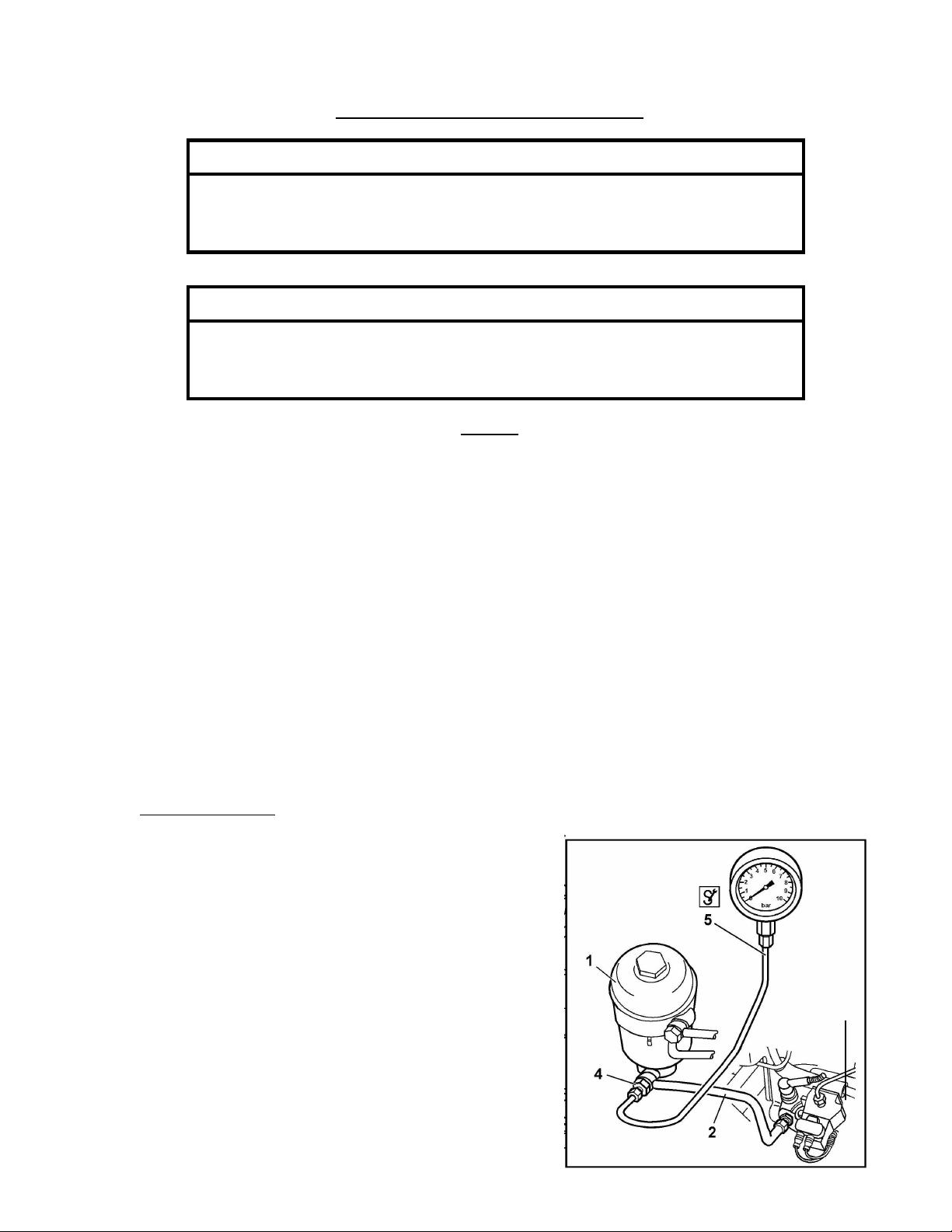
a) Gauge Installation – setup 1: (after the fuel filter):
1 – Fuel filter housing
2 – Fuel outlet line
3 – Unit Pump
4 – Fitting
5 – Mechanical gauge

2
NOTE:
The fitting applied in both setups is not a special tool and it is not
included on the Mercedes-Benz kit or SPX kit.
This fitting is a component and it can be ordered from Canton
PDC under part number 915039012205.
a) Two fuel pressure measurements are required for this test:
Fuel pressure test at idle rpm ..............................................................29 PSI (2 bar) – minimum
Fuel pressure test at rated rpm ............................................................80 to 95 PSI (5.5 to 6.5 bar)
Maximum difference between fuel filter housing inlet
and outlet pressure ..............................................................................4 PSI (0.3 bar)
6 - Fuel Pressure Test – diagnosis
a) At idle rpm, fuel pressure lower than 29 PSI (2 bar), check the following:
o Pressure valve at the end of the fuel gallery. Look for opening pressure 29 PSI (2 bar)
o Fuel pump assembly (bearing and/or driven gear) – see procedure below
o Fuel system drawing air.
b) At rated rpm, fuel pressure lower than 80 PSI (5.5 bar), check the following:
o Water separator filter condition.
o Check for restriction at the check valve on the PLD heat exchange plate.
o Main fuel filter condition, looking for saturation or any damaged seal allowing flow of fuel from
the pressure side to the return side.
o Look for leaks at the suction lines from the tank.
o Fuel pump assembly (bearing and/or driven gear) – see procedure below.
o Look for leaks and/or damaged fuel pump.
o Check for restriction at the check valve on the fuel filter return line to tank.
c) At rated rpm, for pressure higher than 95 PSI (6.5 bar), check the following:
o Return line and injector spill line, looking for restrictions or bent lines.
o Fuel pressure valve - regulator orifice blocked or restricted.
3
b) Gauge Installation – setup 2: (before the fuel filter):
1 – Fuel filter housing
2 – Fuel outlet line
3 – Fuel Pump
4 – Fitting
5 – Mechanical gauge

3
Checking the fuel pump driven gear bolt torque
This procedure describes how to check the fuel pump assembly looking for play/wear on the fuel pump shaft
drive gear mounting bolt. Any play in this component has a big impact on the engine performance.
1. Remove the fuel pump (1).
2. Set the torque wrench (4) to 22 lbf.ft (30 Nm).
Note: Do not apply a torque over 22 lbf.ft (30 Nm). Excessive torque can cause the bolt/gear failure.
3. Turn the torque wrench (4) as shown by the arrow on the picture A until the torque wrench (4) “clicks”.
This resistance ensures that the fuel pump drive gear is in good condition. In the event of no resistance
found, shaft turning freely, proceed as follows.
4. Remove the cover (5).
5. Remove bolt (6) and gear (7).
6. Check the mounting between bolt (6), gear (7) and shaft (2). Look for damaged parts. Replace any
damaged part in order to avoid it coming loose again.
7. Install gear (7) and bolt (6). Apply sealant to the bolt (6) – Loctite 271. For the correct tightening of the
bolt (6), install the special tool J-46187 to the fuel pump spline and block the shaft (2) movement.
8. Torque bolt (6) to 22 lbf.ft (30 Nm).
9. Install the cover (5). Apply sealant (Loctite 574) on the border. Torque 37 lbf.ft (50 Nm).
10. Install new gasket and the fuel pump (1). Torque to the fuel pump bolts 18lbf.ft (25 Nm).
Picture
A
Picture B
1.Fuel pump 4.Torque wrench
2.Fuel pump shaft 5. Cover
3.Special Tool J-46187 or 6. Bolt
Hex. Key wrench (allen) 12 mm 7. Gear

4
7 - Fuel System Test – Using Minidiag2
CAUTION
To avoid injury when working near or on an operating engine,
remove loose items of clothing, jewelry, and tie back or contain
long hair that could be caught in any moving part causing injury
CAUTION
Diesel engine exhaust and some of its constituents are known to
the state of California to cause cancer, birth defects, and other
reproductive harm.
o Always start and operate an engine in a well-ventilated
area.
o If operating an engine in an enclosed area, vent the
exhaust to the outside.
o Do not modify or tamper with the exhaust system or
emission control system.
NOTE:
Before running the test, warm the engine to normal operating
temperatures: 176F to 203F (80C to 95C)
a) Idle Smoothly Balance (Fuel Delivery):
This test measures the percentage of fuel contribution for each cylinder in order to maintain a smooth
operation at idle. Operational range for this test: from –3%(negative) to 3% (positive).
Identify the cylinder with biggest absolute value – highest positive or lowest negative. The
troubleshooting steps for both conditions are:
1. For highest positive:
o Step 1: Check torque at all the transfer tubes nut (33 lbf.ft / 45 Nm). Run the test
again. If the results are out of the operational range, proceed to the next step.
o Step 2: Find the cylinder with result closest to zero. Swap the injector nozzle holder
and the transfer tube between this cylinder and the cylinder with highest result. Run
the test again. If the highest result follows the injector nozzle holder, replace it. If not
proceed to the next step.
NOTE: After removing the injector nozzle holders and transfer tubes, please check
the coupling area between both components and the seal rings. If any defect or
damaged is found, replace the damaged parts.
o Step 3: Return both injector nozzle holders and transfer tubes to the original position
and run the impact delay time and compression test routines.
2. For lowest negative:

5
o Step 1: Check torque at all the transfer tubes nut (33 lbf.ft / 45 Nm). Run the test
again. If the results are out of the operational range proceed to the next step.
o Step 2: Find the cylinder with the lowest result, remove the injector nozzle holder and
check the opening pressure. If the pressure is lower than the minimum spec (3989
PSI / 275 bar), replace the injector nozzle holder. If the pressure is within the spec,
proceed to the next step.
o Step3: Run the compression test.
b) Impact Delay Time:
This test measures the reaction time of the unit pumps. Operation range: from 1.2 to 2.1 milliseconds
i) Troubleshooting procedure for values out of the operating range:
o Step 1: Check the engine harness from the PLD to the suspected unit pump –
connectors and wire. Look for bad or loose connections and broken wires. If not,
proceed to the next step.
o Step 2: Swap the suspect unit pump with one operating properly and run the test
again - refer to the following sections of the MBE4000 Service Manual – 6SE412:
2.1.1 for unit pump removal and section 2.1.2 for unit pump installation. If the
condition follows the unit pump, replace it.
Table of contents
Other Detroit Diesel Industrial Equipment manuals


Popular Industrial Equipment manuals by other brands


Magpowr
Magpowr Perma-Tork HB6-1 instruction manual

Mapal
Mapal Hydro Dream Chuck Installation and operating instructions

GALILEO TP
GALILEO TP VACSOUND ECO D12 manual

ABB
ABB HT610602 Operation manual

Grundfos
Grundfos PowerAdapt Installation and operating instructions

Hunnebeck
Hunnebeck Edge Protection system user guide


