Bradley Lenox Lockers User manual

Installation
P.O. Box 309, Menomonee Falls, WI 53052-0309
Phone: 1-800-BRADLEY Fax: (262) 251-5817
http:\\www.bradleycorp.com
LK-INSTR-003 Rev A; EN 06-1309
© 2006 Bradley Corporation
Page 1 of 7 9/29/06
Lenox Lockers™
Pedestal Bench
Banc Piédestal
Banco del Pedestal
Table of Contents
Pre-Installation Information . . . . . . . . . . . . . . . . .2
Hardware List . . . . . . . . . . . . . . . . . . . . . . . . . . . .2
Installation . . . . . . . . . . . . . . . . . . . . . . . . . . . . . .3
Table des matières
Avant l’installation . . . . . . . . . . . . . . . . . . . . . . . . .4
Liste de quincaillerie . . . . . . . . . . . . . . . . . . . . . . .4
Installation . . . . . . . . . . . . . . . . . . . . . . . . . . . . . . .5
Contenido
Información previa a la instalación . . . . . . . . . . . .6
Lista del tornillería . . . . . . . . . . . . . . . . . . . . . . . . .6
Instalación . . . . . . . . . . . . . . . . . . . . . . . . . . . . . . .7

Pre-Installation Information
Tools required
• Tape measure
• Power drill
• 3/16" drill bit
• 1/4" masonry drill bit
• Phillips driver bit
Hardware List (hardware provided by Bradley)
2
Lenox Lockers™ Pedestal Bench Installation
9/29/06 Bradley Corporation • LK-INSTR-003 Rev. A; EN 06-1309
FAST-LF017
1/4" x 2-1/4" lg. stud with nut and washer for
securing pedestal to the floor
FAST-S357
#14 x 1-3/4" lg. screw for attaching pedestals to
the bench
IMPORTANT!
Read this entire installation manual to ensure proper installation. When finished with the
installation, file this manual with the owner or maintenance department. Compliance and
conformity to local codes and ordinances is the responsibility of the installer.
Separate all parts from the packaging and make sure all parts are accounted for before
discarding packaging material. If parts are missing, do not begin installation until you
obtain the missing parts.
Accuracy is important when drilling the flange holes.
Review your layout drawings and verify the number of pedestal benches and
components before beginning installation. Refer to your submittal layouts for proper
placement of the pedestal benches.
Make sure all floors are clean and smooth. Remove loose impediments, such as
protruding nails, and other debris which could affect installation. The bench will be as
level as the floor it is secured to. Do not use shims to level the pedestal bench.
Product warranties may be found under "Product Information" on our web site at
www.bradleycorp.com.
THIS
SIDE
UP
Packing List
Installation
.
STD.HANDLE - VENT
.
SEEBOM
LOCKERASSEMBLY
LK187218-1HV
.
.
NTS
SAME
11/30/01
.
.
.
TAM
.
.010
.015
2˚
.015
APP.CHANGEDATE NO. C/N DR. DRAWNBY
DONOT MATERIALSPEC.
DRAWING
SCALE
PARTNO.
NAME
TOLERANCES-
+
3PLACE
ANGLES
FRACTIONS
2PLACE
-+
-
+
-
+
-
SPECIFIED:
OTHERWISE
UNLESS
USEDON
REFERENCE
ACAD#
SCALE
DATE
FIRST DATE
DATE
APPR'D
CH'K'D

Position flanges and mark
hole locations on the floor.
Remove the bench.
Using a 1/4" masonry drill bit,
drill starter holes in the floor
1-1/8" to 1-1/4" deep.
C
D
Insert a stud, thread side up, into each hole.
Place a washer and nut (flush) on top of the
stud and tap on the nut with a hammer until
seated.
Tighten nut to secure bench(es).
Installation Lenox Lockers™ Pedestal Bench
3Bradley Corporation • LK-INSTR-003 Rev. A; EN 06-1309 9/29/06
6"
(152mm)
C
L
Position each pedestal on the
underside of the bench.
Mark the hole locations and
remove the pedestals.
Using a 3/16" drill bit, drill 1/2"
deep starter holes in the bench.
A
BSecure the pedestals with the
#14 x 1-3/4" screws provided.
Pedestal To Bench
Bench to Floor
Installation

4
Lenox Lockers™ Pedestal Bench Installation
9/29/06 Bradley Corporation • LK-INSTR-003 Rev. A; EN 06-1309
Avant l’Installation
Outils nécessaires
• Mètre à ruban
• Perceuse électrique
• Mèche 1/8"
• Mèche à maçonnerie 1/4"
• Embout cruciforme
Liste de quincaillerie (fourni par Bradley)
FAST-LF017
1/4" x 2-1/4" goujon avec écrou et rondelle (banc
sur sol)
FAST-S357
#14 x 1-3/4" vis (piédestal sur banc)
IMPORTANT!
Lire ce manuel d'installation dans son intégralité pour garantir une installation
appropriée. Une fois celle-ci terminée, classer ce manuel auprès du service à la clientèle
ou d'entretien. L'installateur est responsable de la conformité de l'installation aux codes
pour les règlements en vigueur.
Assurez-vous que toutes les pièces sont incluses dans l’emballage et qu’il n’en manque
aucune avant de jeter l’emballage. Ne commencez pas l’assemblage avant de recevoir
les pièces manquantes.
L’exactitude est essentielle lors du perçage de trous à collerette.
Examiner les tracés et vérifier le nombre de bancs sur pieds et de composantes avant
de commencer l’installation. Consulter les tracés pour connaître l’emplacement
approprié des bancs sur piédestals.
S’assurer que tous les sols sont propres et lisses. Éliminer tout obstacle meuble, tel que
des clous saillants et d’autres débris susceptibles d’affecter l’installation. Le banc sera
aussi nivelé que le sol sur lequel il est fixé. Ne pas utiliser de cales pour niveler le banc
sur piédestals.
Les garanties de produits figurent sous la rubrique « Informations techniques » sur
notre site Internet à www.bradleycorp.com.
THIS
SIDE
UP
Packing List
Installation
.
STD.HANDLE - VENT
.
SEEBOM
LOCKERASSEMBLY
LK187218-1HV
.
.
NTS
SAME
11/30/01
.
.
.
TAM
.
.010
.015
2˚
.015
APP.CHANGEDATE NO. C/N DR. DRAWNBY
DONOT MATERIALSPEC.
DRAWING
SCALE
PARTNO.
NAME
TOLERANCES-
+
3PLACE
ANGLES
FRACTIONS
2PLACE
-+
-
+
-
+
-
SPECIFIED:
OTHERWISE
UNLESS
USEDON
REFERENCE
ACAD#
SCALE
DATE
FIRST DATE
DATE
APPR'D
CH'K'D

Position flanges and mark
hole locations on the floor.
Remove the bench.
Using a 1/4" masonry drill bit,
drill starter holes in the floor
1-1/8" to 1-1/4" deep.
C
D
Insert a stud, thread side up, into each hole.
Place a washer and nut (flush) on top of the
stud and tap on the nut with a hammer until
seated.
Tighten nut to secure bench(es).
6"
(152mm)
C
L
Position each pedestal on the
underside of the bench.
Mark the hole locations and
remove the pedestals.
Using a 3/16" drill bit, drill 1/2"
deep starter holes in the bench.
A
BSecure the pedestals with the
#14 x 1-3/4" screws provided.
Piédestal sur banc
Banc sur sol
Insérer un goujon, filet vers le haut, dans chaque trou.
Placer une rondelle et un écrou (à fleur) sur le haut du goujon
et taper sur l’écrou avec un marteau jusqu’à ce qu’il soit bien
installé.
Serrer l’écrou pour fixer le ou les bancs.
Positionner les brides et marquer les
emplacements de trous sur le sol. Retirer
le banc.
À l’aide d’une mèche à maçonnerie 1/4",
percer des avant-trous dans le sol entre 29
mm et 32 mm (1-1/8" et 1-1/4") de
profondeur.
Positionner chaque piédestal sur le
dessous du banc.
Marquer les emplacements des trous et
retirer les piédestals.
À l’aide d’une mèche 3/16", percer des
avant-trous de 13 mm (1/2") de
profondeur dans le banc.
Fixer les piédestals à l’aide des vis n°
14 x 1-3/4" fournies.
Installation Lenox Lockers™ Pedestal Bench
5Bradley Corporation • LK-INSTR-003 Rev. A; EN 06-1309 9/29/06
Installation

Información previa a la instalación
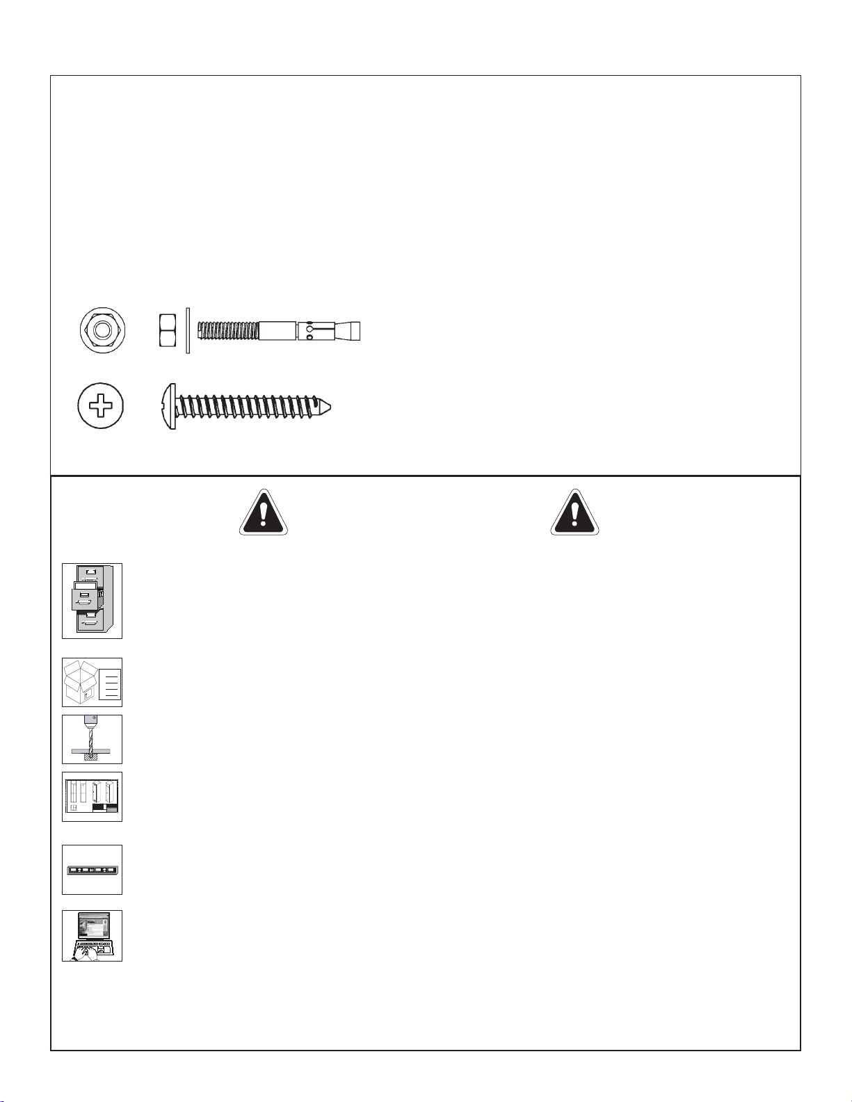
Herramientas requeridas
• Cinta métrica
• Taladro eléctrico
• Broca de taladro de 1/8"
• Broca de taladro para hormigón de 1/4"
• Broca de destornillador Phillips
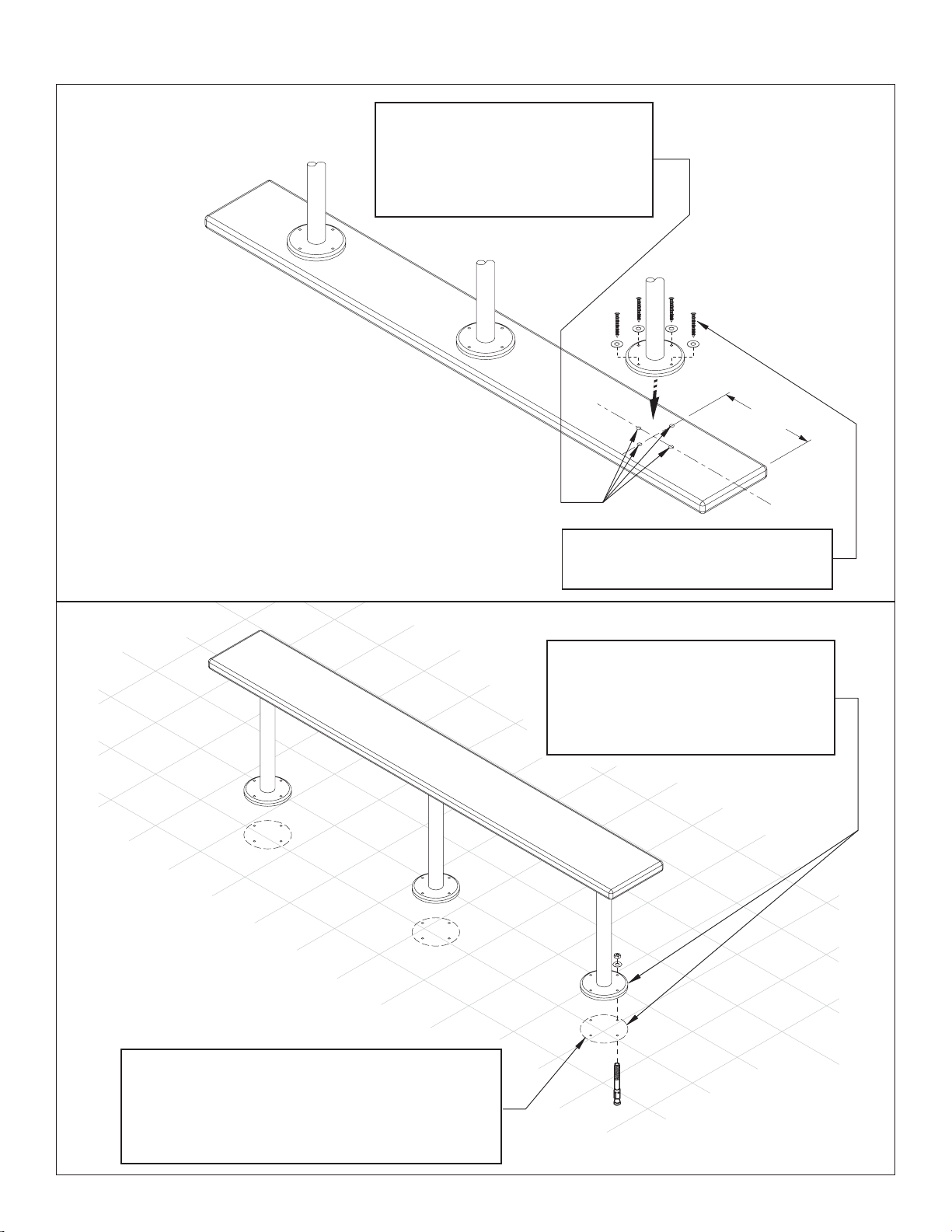
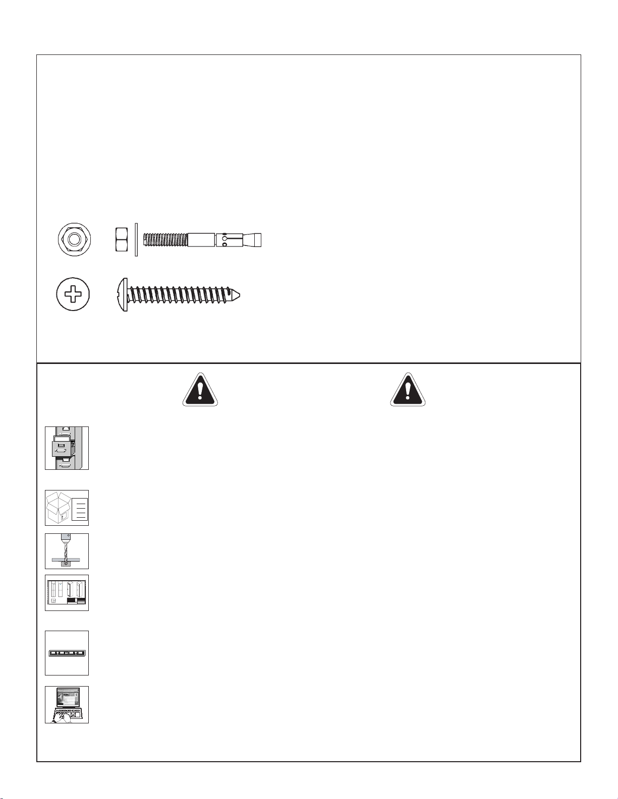
Lista del tornillería (proporcionado por Bradley)
FAST-LF017
1/4" x 2-1/4" perno con tuerca y arandela (de la
banca al piso)
FAST-S357
#14 x 1-3/4" tornillo (del pedestal a la banca)
¡IMPORTANTE!
Lea en su totalidad este manual de instalación para garantizar una instalación adecuada.
Una vez que termine la instalación, entregue este manual al propietario o al Departamento de
Mantenimiento. Es responsabilidad de quien instale el equipo cumplir con los códigos para
las códigos y ordenanzas locales.
Separar todas las piezas del material de embalaje y asegurarse que todas las piezas estén
incluídas antes de desechar cualquier material de embalaje. Si faltase alguna pieza, no
intentar instalar la unidad combinada Bradley hasta obtener las piezas faltantes.
La precisión es importante al taladrar los orificios de la brida.
Revise sus planos y verifique el número de bancas con pedestal y componentes antes de
comenzar la instalación. Consulte la posición correcta de las bancas con pedestal en el
diagrama de distribución.
Asegúrese de que el piso esté limpio y liso. Retire todos los obstáculos sueltos, como
clavos sobresalientes y otros desechos que pudiesen afectar la instalación. La banca estará
nivelada según el piso al que se fije. No use cuñas para nivelar la banca con pedestal.
Las garantías del producto se pueden encontrar en "Información del producto" o en nuestro
sitio Web, www.bradleycorp.com.
THIS
SIDE
UP
Packing List
Installation
.
STD.HANDLE - VENT
.
SEEBOM
LOCKERASSEMBLY
LK187218-1HV
.
.
NTS
SAME
11/30/01
.
.
.
TAM
.
.010
.015
2˚
.015
APP.CHANGEDATE NO. C/N DR. DRAWNBY
DONOT MATERIALSPEC.
DRAWING
SCALE
PARTNO.
NAME
TOLERANCES-
+
3PLACE
ANGLES
FRACTIONS
2PLACE
-+
-
+
-
+
-
SPECIFIED:
OTHERWISE
UNLESS
USEDON
REFERENCE
ACAD#
SCALE
DATE
FIRST DATE
DATE
APPR'D
CH'K'D
6
Lenox Lockers™ Pedestal Bench Installation
9/29/06 Bradley Corporation • LK-INSTR-003 Rev. A; EN 06-1309

Position flanges and mark
hole locations on the floor.
Remove the bench.
Using a 1/4" masonry drill bit,
drill starter holes in the floor
1-1/8" to 1-1/4" deep.
C
D
Insert a stud, thread side up, into each hole.
Place a washer and nut (flush) on top of the
stud and tap on the nut with a hammer until
seated.
Tighten nut to secure bench(es).
6"
(152mm)
C
L
Position each pedestal on the
underside of the bench.
Mark the hole locations and
remove the pedestals.
Using a 3/16" drill bit, drill 1/2"
deep starter holes in the bench.
A
BSecure the pedestals with the
#14 x 1-3/4" screws provided.
Del pedestal a la banca
De la banca al piso
Inserte un perno, con las roscas hacia arriba, en cada orificio.
Coloque una arandela y una tuerca (a ras) en la parte
superior del perno y golpee suavemente sobre la tuerca con
un martillo hasta que se asiente.
Apriete la tuerca para fijar la banca.
Coloque las bridas y marque la posición de
los orificios en el piso. Retire la banca.
Con una broca de taladro para hormigón
de 1/4", taladre orificios iniciales en el piso
de 2,85 cm (1-1/8") a 3,17 cm (1-1/4") de
profundidad.
Coloque cada pedestal debajo de la banca.
Marque las posiciones de los orificios y
retire los pedestales.
Con una broca de taladro de 3/16", taladre
orificios iniciales de 1,27 cm (1/2") de
profundidad.
Fije los pedestales con los tornillos Nº
14 x 1-3/4" que se proporcionan.
Installation Lenox Lockers™ Pedestal Bench
7Bradley Corporation • LK-INSTR-003 Rev. A; EN 06-1309 9/29/06
Instalación
Table of contents
Other Bradley Industrial Equipment manuals