DETROIT GHG17 User manual
Detroit Diesel 13400 Outer Drive, West / Detroit, Michigan 48239-4001
No.: 17 TS-12Rev
December 9, 2019
TO:
Service Locations
FROM:
Service Systems Development
SUBJECT:
GHG17 Heavy Duty Engine Platform 1-BOX™ Aftertreatment System
(ATS) Wire Harness
ISSUE
For GHG17, the main Aftertreatment Control Module (ACM) harness shifted from a Daimler
Trucks North America (or vehicle OEM) part to a Detroit™part. There are two main issues with
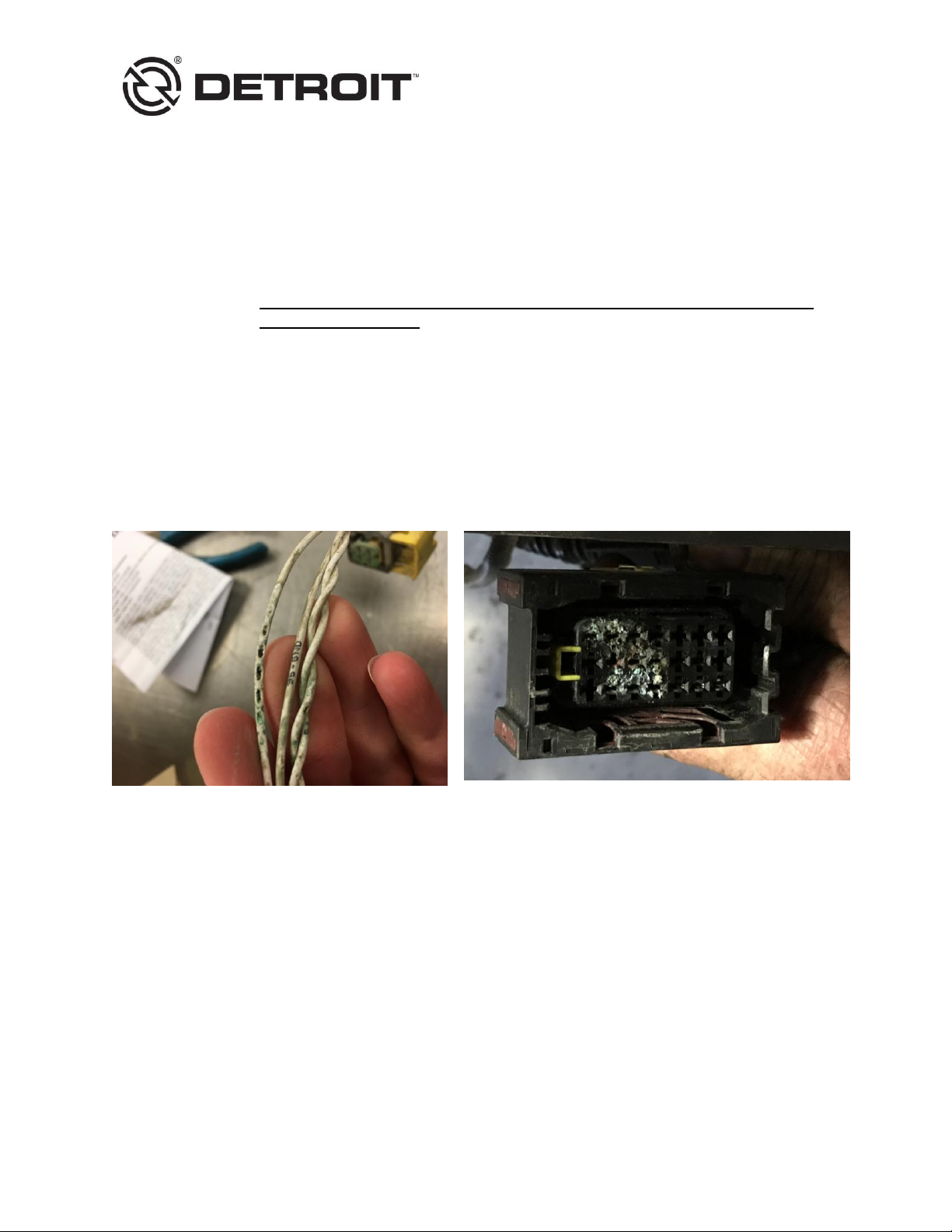
the 1-BOX™ ATS harness. Reference Figure 1.
Harness shows chaffing on the branch to the 21-pin connector and Soot Sensor
Harness and ACM show corrosion at the 21-pin connector
Figure 1 –GHG17 1-BOX™ ATS Wire Harness
These issues can cause various electrical fault codes such as:
MCM fault code SPN 1231/FMI 9 - ACM Message Not Received or has Stopped Arriving
CPC fault code SPN 625/FMI 9 - ACM PT-CAN DM1 Message Not Received or has
Stopped Arriving
CAUSE
The chaffing is caused by vibration and dirt collecting inside the harness conduit. The water
intrusion at the 21-pin connector is a secondary failure due to chafing and water entering the
harness wiring.

17 TS-12Rev - 2 - 12/9/2019
REQUIRED ACTION
Anti-chaffing tape should be applied to the current ATS harness, or to a new replacement
harness if it does not have the tape. See the Repair Procedure section for instructions on
installing the tape.
REQUIRED MATERIAL
If the harness needs replacing, the current production and service ATS harness is P/N:
A4721504320. It superseded former P/N: A4721503620 with approximate ATS S/N:
1240000769034 at the truck plants in July, 2017. The new harness has anti-chaffing tape under
the loom. Either part number is acceptable to use in a repair. Refer to the eParts Catalog on
ddcsn.com with the specific engine serial number to verify the correct ATS harness part
number.
If repairing or installing harness P/N: A4721503620, portions of the harness will need to be
wrapped with anti-chaffing tape such as DTNA P/N: 48-25910-003 or commercially available
tape, Coroplast 832 MPX. The DTNA tape is 82’ long x 1” wide, and is enough for multiple
vehicles. See the Repair Procedure section for instructions on installing the tape.
REPAIR PROCEDURE
Follow the procedure below.
ELECTRICAL SHOCK
To avoid injury from electrical shock, use care when connecting battery cables. The
magnetic switch studs are at battery voltage.
1. Shut off engine and apply the parking brake, chock the wheels, disconnect vehicle battery
power, and perform any other applicable safety steps.
2. If necessary, remove the passenger side fairing. Refer to OEM procedures.
3. Allow the ATS time to cool.

17 TS-12Rev - 3 - 12/9/2019
4. Remove the six bolts securing the ACM protective cover to the ATS. Reference Figure 2.
Figure 2 –ACM Cover
5. Note the location of the zip ties securing the wiring harness to the ATS and the harness
routing location. Remove the zip ties securing the wiring harness to the ATS. Reference
Figure 3.
Figure 3 –Harness Routing and Zip Tie Location

17 TS-12Rev - 4 - 12/9/2019
6. Remove the following plastic connector clips. Reference Figure 4.
Two 90-degree elbows
Three T-fittings
21-pin connector fitting
Soot Sensor fitting
Figure 4 –Harness Clip Removal
7. Remove the convoluted tubing using scissors or tool DKI0CHA17002-13 from the Chassis
Terminal Extraction Tool Kit DKI0CHA17002. Take care not to cut the wire harness. DO
NOT USE A RAZOR BLADE. If using the Harness Fiber Tape Wrap Cutting Tool, use the
sharp end to make an incision in the tubing, and then insert the blunt end to cut the tubing.
Reference Figure 5.
Figure 5 –Harness Fiber Tape Wrap Cutting Tool

17 TS-12Rev - 5 - 12/9/2019
8. Carefully remove all convoluted tubing shown in red below. Reference Figure 6.
Figure 6 –Convoluted Tubing Removal
9. Inspect all exposed wires for damage or corrosion, looking carefully for wire insulation that
has worn through, exposing the wire core. Is there exposed wire core? Reference Figure 7.
a. Yes; replace the ATS harness. Reference the removal and installation sections for the 1-
BOX™ Aftertreatment Harness in the GHG17 Heavy Duty Workshop Manual (DDC-SVC-
MAN-0190). Instructions for adding anti-chaffing tape are further below. Go to step 11.
b. No; go to step 10.
No wire core exposure
Wire core exposure-REPLACE harness
Figure 7 –Wire Harness Inspection
17 TS-12Rev - 6 - 12/9/2019
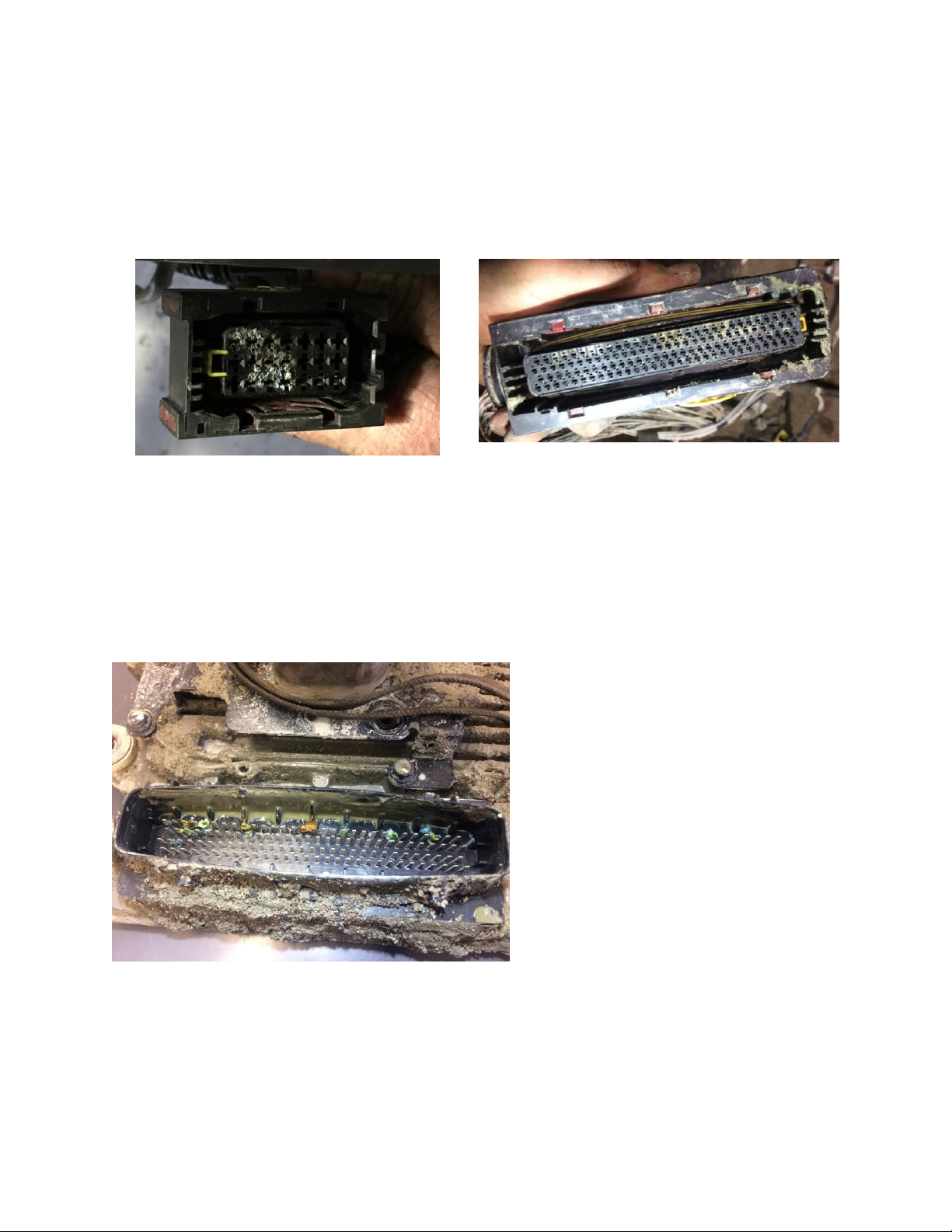
10. Inspect the ATS harness 21-pin and 120-pin connectors for excessive corrosion. Reference
Figure 8. Is excessive corrosion present at one or both connectors?
a. Yes; replace the ATS harness. Reference the removal and installation sections for the 1-
BOX™ Aftertreatment Harness in the GHG17 Heavy Duty Workshop Manual (DDC-
SVC-MAN-0190). Instructions for adding anti-chaffing tape are further below.
b. No; the harness will be reused.
Figure 8 –ATS Harness 21-pin and 120-pin Connector Inspection
11. Inspect the ACM 21-pin and 120-pin connectors for excessive corrosion. Reference Figure
9. Is excessive corrosion present at one or both connectors?
a. Yes; replace the ACM. Reference the removal and installation sections for the 1-BOX™
Aftertreatment Control Module in the GHG17 Heavy Duty Workshop Manual (DDC-SVC-
MAN-0190). Go to step 13.
b. No; go to step 12.
Figure 9 –ACM 21-pin and 120-pin Connector Inspection
17 TS-12Rev - 7 - 12/9/2019
EYE INJURY
To avoid injury from flying debris when using compressed air, wear adequate eye
protection (face shield or safety goggles) and do not exceed 40 psi (276 kPa) air
pressure.
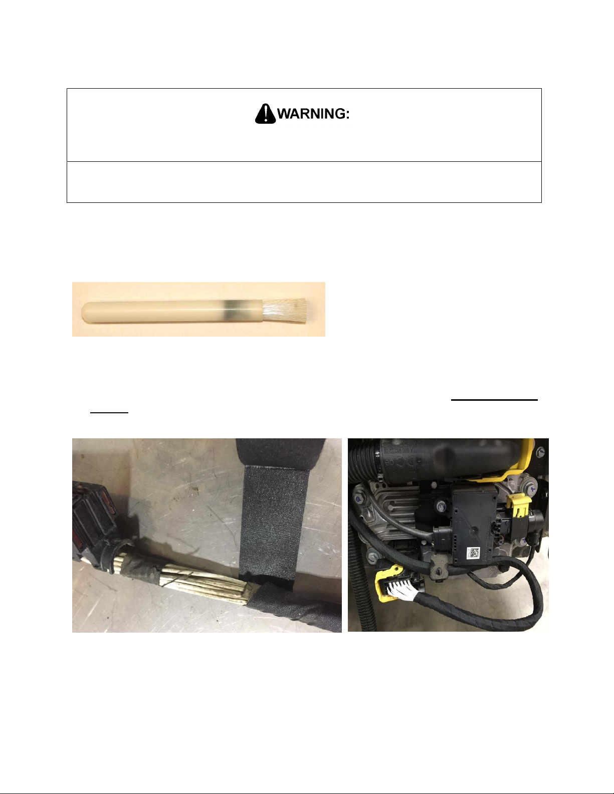
12. If light corrosion is present in the ACM 21-pin and 120-pin connectors, clean them with
commercially available electrical contact cleaner and an insulative nylon brush such as
Techni-Stat Insulative Brush P/N: 758PR499 (reference Figure 10) or Techni-Tool ESD
Brush P/N: 758PR121. Gently blow out the connector with compressed air until dry.
Figure 10 –Insulative Nylon Brush used for Connector Cleaning
13. If reusing the existing ATS harness or installing a new ATS harness P/N: A4721503620,
install anti-chaffing tape around all exposed wires as shown in Figure 11.Overlap the tape
by 50% and proceed to step 14. If installing a new ATS harness P/N: A4721504320, note
that it already comes with anti-chaffing tape under the loom and proceed to step 15.
Figure 11 –Anti-Chaffing Tape Installation

17 TS-12Rev - 8 - 12/9/2019
14. Reinstall the convoluted tubing and install existing elbows, tees and connector fittings. Fully
apply electrical tape around the convoluted tubing. Reference Figure 12.
Figure 12 –Tape Installation
15. Connect the 120-pin and 21-pin electrical connectors and make sure the latches are fully
closed. Connect the soot sensor electrical connector. Install new zip ties in the original
locations, securing the harness to the ATS. Reference Figure 13.
Figure 13 –Zip Tie Location

17 TS-12Rev - 9 - 12/9/2019
16. Install the ACM protective cover and hand-tighten the bolts. Torque the bolts to 10 N·m (7.4
lb·ft). Reference Figure 14.
Figure 14 –ACM Cover Installation
CLAIM PROCESS
Normal Detroit™ in-warranty procedures apply. Proactive installation of the tape or ATS
harness replacement is not allowed under warranty.
If a mechanical failure is found in warranty, file the claim as follows:
Claim type: 1 (base warranty) or 2 (extended coverage)
Primary Failed Part: A4721503620
Fault type: 22
Parts return: Required
Troubleshooting may include the following labor operations:
Labor Operation SRT939-6225D, Computer Hook Up Used In Diagnostics
Labor Operation 3RB-000EE, MCM/CPC/ACM/TCM Diagnostics-Difficult
Labor Operation 246-6130E, ATS-After Treatment Device Harness R&R (One Box ATS)
Labor Operation 246-6133E ATS-After Treatment Device Harness Anti-Chaffing Tape
Installation (Harness Installed On Vehicle)
Labor Operation 246-6134E ATS-After Treatment Device Harness Anti-Chaffing Tape
Installation (Harness Removed From Vehicle)
Labor Operation 246-6195E, ATS-ACM (Aftertreatment Control Module) R&R (If
needed/replacement)
Admin Labor Operation 939-6010B

17 TS-12Rev - 10 - 12/9/2019
CONTACT INFORMATION
Please contact the Detroit™Customer Support Center at 800-445-1980 or email
Table of contents


