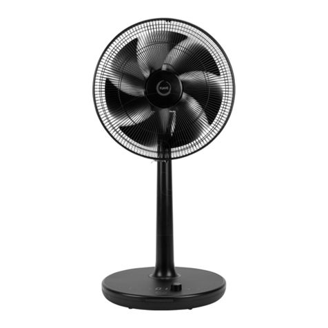
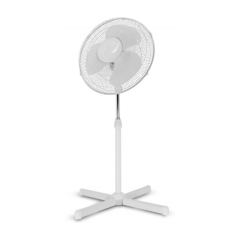
DETROIT DFS75 User manual

WARRANTY INFORMATION
This warranty is provided by Total Tools (Importing) Pty Ltd of 19 Grimes Court, Derrimut, VIC 3030.
Phone: 03 9394 4300 (we, us, our).
Express warranty
Subject to the exclusions set out below, we warrant that this product will be free from defects in materials or
workmanship for a period of 12 months from the date of purchase.
The benefits conferred by this warranty are in addition to all rights and remedies which you may be entitled to under
the Australian Consumer Law, and any other statutory rights you may have under other applicable laws.
This warranty does not exclude, restrict or modify any such rights or remedies.
Warranty exclusions
This express warranty does not apply where a defect or other issue with the product is caused by normal wear and
tear, misuse or abuse of the product.
Consumer guarantees
Our goods come with guarantees that cannot be excluded under the Australian Consumer Law. You are entitled to a
replacement or refund for a major failure and for compensation for any other reasonably foreseeable loss or damage.
You are also entitled to have the goods repaired or replaced if the goods fail to be of acceptable quality and the
failure does not amount to a major failure.
Warranty claims
To make a claim under this warranty, you must bring the product along with the proof of purchase and any other
documentary evidence which you think is relevant to the Total Tools’ place of purchase where the claim will be
handled on our behalf. Any cost incurred by you in bringing the product to the place of purchase will be borne by you.
To make a claim under this warranty, the product and proof of purchase must be returned to the Total Tools place of
purchase during the warranty period specified above.
If your warranty claim is accepted, we (or the Total Tools store that handles the claim on our behalf) will, at our
discretion, repair or replace the product, or refund money to you and take back the product.
PEDESTAL FAN & WALL FAN
Model No: DFS75 .. 80788
Model No: DFB75 .. 80789
OPERATING
INSTRUCTIONS
TO PREVENT SERIOUS INJURY, READ
AND UNDERSTAND ALL WARNINGS
AND INSTRUCTIONS BEFORE USE.
Model no.
DFB75
Model no.
DFS75

PAGE 2 PAGE 11
This product is intended for indoor use only.
Always operate the product from a power source of the same voltage, frequency and rating
as indicated on the product identification plate.
To reduce the risk of electric shock, do not use this fan with any solid state speed control
device.
This appliance is not intended for use by persons (including children) with reduced physical,
sensory or mental capabilities, or lack of experience and knowledge, unless they have been
given supervision or instruction concerning use of the appliance by a person responsible for
their safety.
Do not insert fingers or any other foreign object through the front and rear guards into the
blade.
Close supervision is necessary when any product is used by or near children or infirm
persons. Do not allow children to use it as a toy.
Do not operate any product with a damaged cord or plug, after the product malfunctions, is
dropped or appears damaged in any way. Return the complete product to the place of
purchase for inspection, repair, or replacement.
To reduce the risk of electric shock, do not immerse or expose the product or flexible cord to
rain,moisture, or any liquid.
This product should not be used in the immediate vicinity of water, such as sinks, bathtubs,
washbowls, swimming pool, etc. where the likelihood of immersion or splashing could
occur.
Switch off and unplug from outlet when not in use, before assembling or disassembling
parts, and before cleaning. Fully assemble the fan before switching on.
Avoid contact with moving parts. Do not insert any object through the grill when the fan is
operating.
Do not cover the grill, or operate in close proximity to curtains, etc.
Always disconnect the fan when moving it from one location to another.
The use of attachments or accessories not recommended or sold by the product distributor
may cause personal or property hazards or injuries.
SAFETY INSTRUCTIONS

PAGE 10 PAGE 3
SAFETY INSTRUCTIONS CONTINUED
Never attempt to make any modifications to or repair the product yourself.
Have it repaired by a qualified person only.
Place the appliance on a flat and dry surface.
Manufacturer takes no responsibility for any damage caused by incorrect use.
FAN DIMENSIONS
EXPLOSION VIEW & PARTS BREAKDOWN
Item
Model
A
B
C E F G H L
min max
DFS75 810 1500 1900 305 1250
DFB75 810 305 850 500 125 12.5 400
28, 29, 30, 31.
9, 10, 11, 12,
18, 17, 16.19
20 22
15
8
6
7
27
26
25
24
Serial No. Item No. Des. QTY Spec./Material Remark
6 GB818-85 Cross screw 1 M6X12 Plate color zinc
7 FB.FB-65-040-040-000 Under connector 1 HT-100 Spray coating
8 GB818-85 Cross screw 1 M6X20 Plate color zinc
9 GB95-85 Washer 1 ∮12 Plate color zinc
10 GB593-85 Spring washer 1 ∮12 Plate color zinc
11 GB52-76 Hex nut 1 M12X40 Plate color zinc
12 GB30-76 Hex bolt 1 M12X40 Plate color zinc
15 FB.FB-65-011-000-010 Motor assembled indication 1 2M Cord
16 FS.FB-65-011-070-000 Fit washer 4 D15 d6.5 h1.5 Plate color zinc
17 GB593-85 Spring washer 4 ∮6 Plate color zinc
18 GB818-85 Cross screw 4 M6X16 Plate color zinc
19 FS.FB-65-030-000-000 Fan blade 1 Spray coating
20 FS.FB-65-020-020-000 Front net 1 Spray coating
21 FS.FB-65-020-010-000 Back net 1 Spray coating
23 FS.FB-65-070-020-000 Rating label 1 Label
24 FB-65-061-000-000 Hanger wall combination 1 Spray coating
25 GB30-76 Hex bolt 1 M8X25 Plate color zinc
26 GB30-76 Hex bolt 1 M8X20 Plate color zinc
27 FB-65-060-030-000 Hanger wall and elbow combination 1 §=1.2X∮32/A3 High frequency tube Spray coating
28 KDDT-360 Cable clamp 1 ∮6/NYLON1010
29 GB95-85 Washer 1 ∮4 Plate color zinc
30 GB593-85 Spring washer 1
∮
4 Plate color zinc
31 GB70-76 Semicircular screw 1 M4X8 Plate color zinc

PAGE 4 PAGE 9
1) Fit REAR GUARD of fan onto the MOTOR and secure
with 4 screws provided. Ensure screws are tight to avoid
vibration noise
2) Fit BLADE to shaft and lock blade SET SCREW.
3) Fit FRONT GUARD to rear guard using clips provided.
4) Fit OUTER TUBE onto CAST IRON BASE and secure
with the BOLT. Then fit COVER RING onto CAST COUPLING.
5) Screw out PLASTIC KNOB on column then fit INNER
TUBE. Secure grub screw with key.
6) Fit MOTOR onto MALE SUPPORTER. Adjust to
suitable height at coupling then lock the MALE SUPPORTER SET
SCREW.
7) Secure locking screw on FEMALE SUPPORTER for
desired head angle / tilt. To adjust the head tilt, loosen the nut
above the female support, then re-secure the nut after adjust-
ment.
EXPLOSION VIEW & PARTS BREAKDOWN
PEDESTAL FAN ASSEMBLY
FEMALE SUPPORTER
SET SCREW
INNER TUBE
COUPLING
OUTER TUBE
CAST COUPLING
CAST IRON BASE
PLASTIC KNOB
MALE
SUPPORTER
SHAFT
OSCILLIATING
ADJUSTMENT
SCREW
MOTOR
REAR GUARD
BLADE
SET SCREW
FRONT GUARD
13
15
19
20
21
1
5
14
6
7
8
9, 10, 11, 12.
2, 3, 4.
18, 17, 16.
Serial No. Item No. Des. QTY Spec./Material Remark
1 FS-75-050-000-000 Cross base 1 600/HT100 Spray coating
2 FS-75-040-030-000 Washer 1 D60 d12.5 §3 Plate color zinc
3 GB593-85 Spring washer 1 ∮12 Plate color zinc
4 GB5780-86 Hex bolt 1 M12X40 Spray coating
5 FS-75-040-000-000 Supporting tube 1 Plate color zinc
6 GB818-85 Cross screw 1 M6X12 Spray coating
7 FS.FB-75-040-040-000 Under connector 1 HT-100
8 GB818-85 Cross screw 1 M6X12 Plate color zinc
9 GB95-85 Washer 1 ∮12 Plate color zinc
10 GB593-85 Spring washer 1 ∮12 Plate color zinc
11 GB52-76 Hex nut 1 M12 Plate color zinc
12 GB30-76 Hex bolt 1 ∮12X40 Plate color zinc
13 FS.FB-75-070-020-000 Rating label 1 Label Plate color zinc
14 Power outlet 1 RVV 2X0.75+0.75M
2
Plate color zinc
15 FS.FB-75-011-000-010 Motor assembled indication 1 Plate color zinc
16 FS.FB-75-011-070-000 Fit washer 4 D15 d6.5 h1.5 2M Cord
17 GB593-85 Spring washer 4 ∮6 Plate color zinc
18 GB818-85 Cross screw 4 M6X16 Plate color zinc
19 FS.FB-75-030-000-000 Fan blade 1 Aluminum Plate color zinc
20 FS.FB-75-020-020-000 Front net 1 Spray coating
21 FS.FB-75-020-010-000 Back net 1 Spray coating
22 FS.FB-75-070-040-000 Net label 1 Aluminum Spray coating

1) Complete points 1-3 on page 4.
2) Attach the wall mount base to the wall by drilling two holes with a M10*80
drill bit. Secure with the two M12 screws provided.
NOTE: Installation height should be a minimum of 2.5 metres from the ground.
IMPORTANT: Check wall is suitable for mounting and supporting the wall fan.
3) Insert the BEND TUBE through the two “U” shape slots provided in the wall
mount base & lock them into position using the two screws provided.
NOTE: The Bend tube can be positioned either upwards or downwards. You must orient
female support upward by removing the screw, repositioning & resecuring. Never attach
the fan so it is hanging below the female supporter.
PAGE 8 PAGE 5
WALL FAN ASSEMBLY
ELECTRICAL DIAGRAM
SPECIFICATIONS
(FRONT VIEW)
Model Description Size
(mm)
Volt
(V~)
Freq
(Hz)
Watts
(W)
Air Flow
(m3/min)
DFS75 Pedestal Fan 750 220-240 50 280 290
DFB75 Wall Fan 750 220-240 50 280 290
The data above is for reference only and may change without notice
Wall
Wall mount base
Fixing bolts
Bend Tube
Cement Washer
Spring Washer
Nut
Install the screw

4)
Insert the motor into the female support and secure with the screw.
5) Secure locking screw on FEMALE SUPPORTER for desired head angle / tilt. To
adjust the head tilt, loosen the nut above the female support, then re-secure the nut after
adjustment.
WARNING! Make sure all parts are assembled correctly and connections are tight.
WARNING! If supply cable to too tight the oscillating motion can cause damage - ensure
sufficient section of cable to avoid damage.
ENVIRONMENT OF USE
1) The max relative humidity is 90%(when in 25℃);
2) Below 1000 metres altitude.
OPERATION
1) Make sure the Fans voltage is in accordance with local voltage before use.
2) The fan is recommended for use in ordinary indoor situations, but not at high humidity.
3) To turn on select the desired speed setting
0 - Off
1 - Slow
2 - Medium
3 - Fast
4) For fixed air flow ensure the swing arm is not connected to the fan motor
5) For oscillating air flow ensure the swing arm is connected to the fan motor by rotating
the oscillating adjustment screw in an anti-clockwise direction.
6) Unplug the fan when not in use.
WALL FAN ASSEMBLY CONTINUED
PAGE 6 PAGE 7
FIG 4 – The fan head in the OSCILLATION
posion. Oscillaon is 0-90°.
FIG 3 – For an OSCILLATING fan head, turn the
OSCILLATING ADJUSTMENT screw anclockwise
to aach SWING ARM to fan head
FIG 1
– The fan switch on the OFF posion
FIG 2 – The fan head in the FIXED air flow
posion
SWING ARM
MAINTENANCE
3) To ensure prolonged safe use ensure you have this unit inpected, cleaned & moving
parts lubricated by a qualified person after every 1000 hours of use.
4) Regularly inspect the cord & plug & do not use if damaged. A lisenced electrician is
required to repair or replace the cord & plug.
5) Any other repairs or maintenance must be performed by a qualified person.
LOCATING SCREW
FEMALE SUPPORTER
FAN HEAD
This manual suits for next models
1
Table of contents
Popular Fan manuals by other brands

Philips
Philips Essence 5000 Series manual

YUHAO
YUHAO 1086 installation instructions

Airflow
Airflow QT 150T Installation and operating instructions

Suntec Wellness
Suntec Wellness KLIMATRONIC CoolBreeze 1500 TV manual

Panasonic
Panasonic FV-08-11VFL5 installation instructions

Luma
Luma MF26B 26 owner's manual