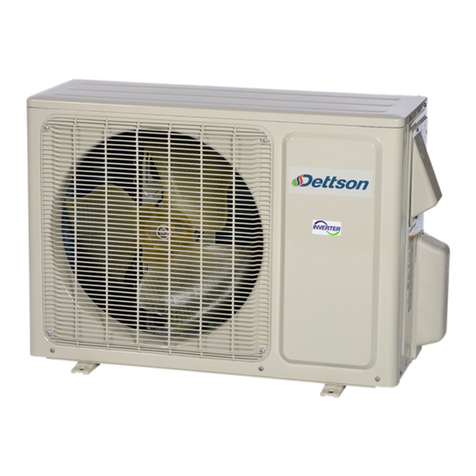
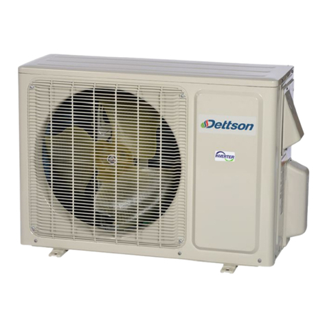
Dettson COND-OCD-09 Assembly instructions

INSTALLATION INSTRUCTIONS AND
HOMEOWNER’S MANUAL
Models:
COND-OCD-09
COND-OCD-12
COND-OCD-18
COND-OCD-24
COND-OCD-30
COND-OCD-36
INSTALLER / SERVICE TECHNICIAN:
Use the information in this manual for the installation / servicing and keep the document near the furnace
for future reference.
Communication wire connected between the indoor and outdoor units must be rated for at least 120VAC,
they are protected by the outdoor unit breaker and must be sized appropriatly.
Do not install any metering device on the indoor coil. The expension valve is located in the outdoor unit.
If a metering device is already installed in the indoor coil, it must be removed.
Both refrigerant lines must be separately insulated in order to avoid condensation and to ensure proper
efficiency.
COND-OCD -09 -12 -18 -24 -30 -36
Liquid line dia (In) 1/4 1/4 1/4 1/4 1/4 1/4
Gas line dia (In) 3/8 1/2 5/8 5/8 5/8 5/8
HOMEOWNER:
Please keep this manual near the furnace for future reference.
CAUTION:
Do not tamper with the unit or its controls. Call a qualified service technician.
Manufactured by:
Dettson Industries Inc.
Sherbrooke, Qc, Canada
www.dettson.com
Printed in Canada on 2020-05-08 X40257 Rev.A
100% recycled paper

Table of Contents
1 SAFETY 3
1.1 Warning......................... 3
1.2 Caution.......................... 3
2 Specifications 4
3 Installation 5
3.1 Notices.......................... 5
3.2 Installation Site . . . . . . . . . . . . . . . . . . . . 5
3.3 Safety Precautions for Electric Appliances. 5
3.4 Clearances....................... 6
3.5 IndoorCoil ....................... 6
3.6 Interface Board (K03081) . . . . . . . . . . . . . 6
3.7 OutdoorUnit...................... 7
3.8 Connection Pipes . . . . . . . . . . . . . . . . . . 8
3.9 OperationTest..................... 8
4 Troubleshooting 9
4.1 Interface Board . . . . . . . . . . . . . . . . . . . . 9
4.2 Outdoor Unit Error Codes . . . . . . . . . . . . 10
5 Commissioning Checklist 11
6 Replacement Parts 12
List of Figures
Figure 1: Installation and Clearances . . . . . 6
Figure 2: Winting Interface Board to ODU . . 7
Figure 3: Indoor Coil Sensor Location . . . . 7
Figure 4: Tube Tightening . . . . . . . . . . . 8
Figure 5: Interface Board . . . . . . . . . . . . 9
Figure 6: ODU Serial Number Location . . . . 11
Figure 7: Exploded View 9k and 12k . . . . . 12
Figure 8: Exploded View 18k and 24k . . . . . 14
Figure 9: Exploded View 30k and 36k . . . . . 16
List of Tables
Table 1: Outdoor Unit Specifications . . . . . 4
Table 3: Checklist After Installation . . . . . . 8
Table 2: Tubing Torque Tightening . . . . . . 8
Table 4: Interface Board Display . . . . . . . 9
Table 5: Outdoor Unit Error Codes . . . . . . 10
Table 6: Parts List 9k and 12k . . . . . . . . . 13
Table 7: Parts List 18k and 24k . . . . . . . . 15
Table 8: Parts List 30k and 36k . . . . . . . . 17
2

1 SAFETY
Installing, starting up, and servicing air conditioner
can be hazardous due to system pressure, electrical
components, and equipment location, etc.
Only trained, qualified installers and service personnel
are allowed to install, start-up, and service this
equipment.
When handling the equipment, observe precautions in
the manual and on tags, stickers on the equipment.
Follow all safety codes. Wear safety glasses and work
with gloves. Keep quenching cloth and fire extinguisher
nearby when brazing.
Read the instructions thoroughly and follow all warnings
or cautions in literature and attached to the unit. Always
follow building codes and current edition of national as
well as local electrical codes.
Recognize the following safety information: Warning:
Incorrect handling could result in personal injury or death
Caution: Incorrect handling may result in minor injury, or
damage to product or property
Recognize the following safety information:
Warning: Incorrect handling could result in personal
injury or death.
Caution: Incorrect handling may result in minor
injury, or damage to product or property.
1.1 Warning
WARNING
All electric work must be performed by a licensed
technician according to local regulations and the
instructions given in this manual.
• Before installing, modifying, or servicing the
system, the main electrical disconnect switch must
be in the OFF position. There may be more than 1
disconnect switch. Lock out and tag switches with
a suitable warning label;
• Never supply power to the unit unless all wiring and
tubing are completed, connected and checked;
• This system contains dangerous electrical voltage.
Incorrect connection or inadequate grounding can
cause personal injury or death. Stick to the wiring
diagram and all the instructions when wiring;
• Have the unit adequately grounded in accordance
with the local electric codes;
• Have all wiring connected tightly. Loose con-
nections may lead to overheating and a possible
fire hazard. All installation or repair work shall
be performed by your dealer or a specialized
subcontractor as there is the risk of fire, electric
shock, explosion or injury.
• Make sure the outdoor unit is installed on a stable,
level surface with no accumulation of snow, leaves,
or trash beside;
• Avoid contact between refrigerant and fire as it
generates poisonous gas;
• Apply specified refrigerant only. Never have it
mixed with any other refrigerant. Never have air
remain in the refrigerant lines as it may lead to
rupture and other hazards;
• Make sure no refrigerant gas is leaking out when
installation is completed;
• Should there be refrigerant leakage, the density
of refrigerant in the air shall in no way exceed its
limited value, or it may lead to explosion;
• Keep your fingers and clothing away from any
moving parts;
• Clear the site after installation. Make sure no
foreign objects are left in the unit;
• Always ensure effective grounding of the unit.
1.2 Caution
CAUTION
• Never install the unit in a place where a combustible
gas might leak, it may lead to fire or explosion;
• Provide a ground fault interrupter (GFI) when it is
installed in a wet environment;
• Never wash the unit with water
• Handle unit transportation with care. The unit
should not be carried by only one person if it is more
than 20 kg;
• Never touch the heat exchanger fins with bare
hands;
• Never touch the compressor or refrigerant piping
without wearing gloves;
• Make sure that the air handler filter is clean;
• Should any emergency occur, stop the unit and
disconnect the power immediately;
• Properly insulate ALL refrigerant tubing from
outdoor units to the interior cooling coil to prevent
condensation.
3

2 Specifications
Table 1 – Outdoor Unit Specifications
Model COND-OCD-09 COND-OCD-12 COND-OCD-18 COND-OCD-24 COND-OCD-30 COND-OCD-36
Power Supply 208/230 VAC, 60 Hz, 1 phase
Cooling Capacity (min-max) BTU/h 9000 (3100-9600) 12000 (3100-13000) 18000 (6800-20000)22000 (6824-27296) 28000 (9490-30030) 33600 (7400-36000)
Heating Capacity (min-max) BTU/h 11000 (1911-12000) 13000 (2400-14000) 19800 (7340-23500) 23000 (6824-30708) 28400 (10000-32990) 34600 (14980-36000)
Cooling Input (min-max) W 630 (160-1300) 960 (200-1350) 1435 (450-2150) 1830 (450-3000) 2750 4100
Heating Input (min-max) W 1020 (160-1350) 1100 (400-1400) 1730 (580-2600) 2000 (450-3000) 2800 3800
Rated Input W 1350 1400 2600 3000 4000 4300
Rated Current A 6.0 6.3 12.5 14.5 17.5 20
MCA A 9 9 16 20 20 24
MOCP A 15 15 25 30 30 40
EER BTU/h/W 14.0 12.5 12.5 12.5 10.3 8.2
COP W/W 3.16 3.46 3.35 3.37 3.00 2.70
SEER 23 22 20 20 18 18
HSPF 10.5 10.1 10.0 10.0 9.0 9.0
Compressor Type Swing Swing Rotary Rotary Rotary Rotary
Compressor LRA A - - 25 25 40 67
Compressor RLA A 4.00 4.00 12.08 11.50 13.50 13.50
Compressor Power Input W 845 845 1440 2550 2450 3010
Fan Motor RLA A - 0.36 0.49 0.65 0.45 0.89
Fan Motor Power W 30 30 60 92 120 170
Air Flow Volume CFM 1059 1177 3200 4000 2354 2589
Throttling Method Electronic expansion valve
Cooling Amb. Temp. °F 0 - 115
Heating Amb. Temp. °F -4 - 75
Sound Pressure Level dB(A) 53 54 55 59 62 65
Unit Dimension (W x H x D) in 33.4 x 21.3 x 12.6 33.4 x 23.3 x 12.6 37.6 x 27.6 x 15.6 38.6 x 31.1 x 16.8 39.5 x 31.1 x 14.6 39.5 x 31.1 x 14.6
Net Weight lb 78 86 106 142 154 161
Refrigerant R410A
Refrigerant Charge oz 45.9 47.6 56.44 81.1 84.66 91.71
Additional Charge oz/ft 0.2 0.2 0.2 0.5 0.5 0.2
Pipe Length ft 24.6 24.6 24.6 24.6 24.6 24.6
Pipe Max Length ft 49 66 82 82 98 98
Pipe Max Height ft 33 33 33 33 33 33
Pipe Diameter See cover page
4

3 Installation
3.1 Notices
CAUTION
1. This unit must be installed only by authorized
qualified technicians according to local and/or
government regulations and in compliance with this
manual;
2. Warning: before obtaining access to terminals, all
supply circuits must be disconnected;
3. The temperature of refrigerant line will be high;
please keep the interconnection cable away from
the copper tube.
3.2 Installation Site
Proper installation site is vital for correct and efficient
operation of the unit. Avoid the following sites where:
• Strong heat sources, vapours, flammable gas or
volatile liquids are emitted;
• High-frequency electro-magnetic waves are gene-
rated by radio equipment, welders and medical
equipment;
• Salt-laden air prevails (such as close to coastal
areas);
• The air is contaminated with industrial vapours and
oils;
• The air contains sulphuric gases such as in hot
spring zones;
• Corrosion or poor air quality exists.
For the outdoor unit:
• Select a site where there is sufficient ventilation;
• Select a site where there is no obstructions
blocking the inlet and outlet;
• The site should be able to withstand the full weight
and vibration;
• Select a dry place, and do not expose the unit to
direct sunlight nor strong winds;
• Make sure that the outdoor unit is installed in
accordance with the installation instructions, and is
convenient for maintenance and repair;
• The maximum pipe height and lenght must comply
with unit specifications (table 1).
3.3 Safety Precautions for Electric
Appliances
1. A dedicated power supply circuit should be used in
accordance with local electrical safety regulations;
2. The unit should be reliably grounded and con-
nected to an exclusive ground device by the
professionals;
3. The circuit breaker must have the functions of
magnetic dripping and heat dripping to prevent
short circuit and overload;
4. The minimum distance between the unit and
combustive surface is 4,9 ft.(1.4935 m);
5. The appliance shall be installed in accordance with
national wiring regulations:
6. An all-pole disconnection switch with a contact
separation of at least 0.1 inch in all poles should
be connected in fixed wiring.
Grounding
1. Please ensure that the unit is reliably grounded;
2. The yellow-green wire in the outdoor unit is the
grounding wire which cannot be used for the other
purposes. Improper grounding may cause electric
shock;
3. The ground must have reliable terminal. Please do
not connect wire with the following: water pipe, gas
pipe, sewer pipe, or other place that professional
personnel consider is unreliable.
4. The model and rated values of fuses should accord
with the silk print on fuse cover or related PCB.
5

3.4 Clearances
Figure 1 – Installation and Clearances
3.5 Indoor Coil
Check the coil for shipping damage and verify the
contents of the box containing the evaporator coil. If you
should find damage, immediately contact the last carrier.
Coils are shipped with a 10 psi dry air holding charge.
Puncture rubber plug on suction line to release charge
before removing plugs. The absence of pressure does
not verify a leak. Check the coil for leaks before installing
or returning it to your wholesaler.
Coil should be level, or pitched slightly toward the drain
connection. Airflow face velocity above 350 ft/min is not
recommended for downflow or counterflow applications
due to potential water blow-off.
For an installation with a Chinook, position the coil on the
supply outlet of the furnace using sheet metal screws.
Drain pans are made of a polymer that can withstand
temperatures up to 232°C (450°F). Maintain a minimum
of 3” clearance over the heat exchanger.
For an installation with a Supreme, position the coil on
the return outlet of the furnace.
A splashguard is included for horizontal installations
(multiposition colis). In downflow and counter flow
configurations, aluminum foil tape must be applied to seal
the top edge of the insulation to the cabinet.
Do not install any metering device on the indoor coil.
The expension valve is located in the outdoor unit.
If a metering device is already installed in the indoor
coil, it must be removed.
Condensate Drain
Coils are equipped with multiple drain connections.
Determine the drain connections to be used and note the
difference between the primary (green) and secondary
(red) openings. Drain plugs are provided for all openings;
remove and discard the appropriate plugs with ½” drive
ratchet and verify that remaining plugs are tight (2.5 ft-
lbs). Attach drain line to pan with ¾” male pipe thread
PVC fittings. Hand tight is adequate – do not over
tighten and do not reduce drain line size.
Route drain line(s) line so they will not be exposed
to freezing temperatures and do not interfere with
accessibility to the coil, air handling system or filter. The
drain should be pitched downward 1” per 10’ with a 2”
trap as close to the coil as possible. If line makes a
second trap, or has an extended run before termination,
a vent tee should be installed after the trap closest to the
pan.
If the coil is located in or above a living space where
damage may occur from condensate overflow, a separate
¾” drain must be provided from the secondary drain
connection. Run this drain to a place in compliance with
local installation codes where it will be noticed when unit
is operational. Condensate flowing from the secondary
drain indicates a plugged primary drain. Prime the trap
with water. Test line for leaks. Test water flow with unit in
operation. An auxiliary drain pan should also be installed
under the unit as specified by most local building codes.
3.6 Interface Board (K03081)
Installation of the interface card is made easy on the
Dettson’s Chinook and Supreme furnaces. Installation
port has been designed on these furnaces. Refer to the
installation instructions provided with the interface board
6

for installation location and thermostat wiring. Wire to the
outdoor unit as shown in the figure.
Figure 2 – Winting Interface Board to ODU
Communication wire connected between the indoor
and outdoor units must be rated for at least 120VAC,
they are protected by the outdoor unit breaker and
must be sized appropriatly.
Coil Sensor
With the interface board kit comes a coil sensor. It must
be properly installed.
1. Attach the provided temperature sensor to the
evaporator coil as shown;
2. Get the wire through the refrigerant line opening;
3. Cut the wire and skin the conductors. Add wire
length if necessary;
4. Connect the two conductors to T1 and TC on the
interface card. The polarity is not important.
Figure 3 – Indoor Coil Sensor Location
3.7 Outdoor Unit
Electrical Wiring
1. Remove the handle on the right side plate of
outdoor unit;
2. Remove cord anchor. Connect and fasten power
connection cord to the terminal board;
3. Secure the power connection cord cord anchor;
4. Make sure the wires have been fastened properly.
NOTE: Incorrect wiring may cause malfunction.
L1 and L2 must be connected to the 208/230VAC power
supply. The unit must be properly grounded via the
ground terminal.
After the wires have been fastened, ensure there is free
space between the connection and fastening places on
the main wire.
Air Purging and Leakage Test
1. Connect charging hose of manifold valve to charge
end of low pressure valve (both high/low must be
tightly shut);
2. Connect joint of charging hose to vacuum pump;
3. Fully open the handle of Lo manifold valve;
4. Open the vacuum pump for vacuumization. At the
beginning, slightly loosen joint nut of low pressure
valve to check if there is air entering. Then, tighten
the nut;
5. Keep evacuating for more than 15 min. and make
sure the reading of multi-meter is -100 kPa(-76
cmHg);
6. Fully open high/low pressure valves;
7. Remove charging hose from charging end of low
pressure valve;
8. Tighten bonnet of low pressure valve.
Condensate Drainage
During heating operation, the condensate and defrosting
water should be drained through the drain hose. Install
the outdoor drain connector in a φ0.98 in hole on the
base plate, and attach the drain hose to the connector so
that the waste water formed in the outdoor unit can be
drained. The hole φ0.98 in must be plugged. Whether
to plug other holes or not will be determined by the
technician.
7

Table 3 – Checklist After Installation
Items to be checked Possible malfunction
Has the unit been fixed firmly? The unit may drop, shake or emit noise
Has the refrigerant leakage test been performed? It may cause insufficient cooling (heating)
Is thermal insulation sufficient? It may cause condensation
Is water drainage satisfactory? It may cause water leakage
Is the voltage in accordance with the rated voltage It may cause electric malfunction or damage the unit
marked on the nameplate?
Is the electric wiring or piping connection installed It may cause electric malfunction or damage parts
correctly and securely?
Has the unit been securely grounded? It may cause electrical leakage
Is the inlet or outlet blocked? It may cause insufficient cooling (heating)
Have the refrigerant charge and the length The refrigerant charge is not accurate
of connection pipes and been recorded?
3.8 Connection Pipes
Align the center of the pipe flare with the relevant
valve. Screw in the flare nut by hand and then tighten
the nut with spanner and torque wrench following the
specifications.
Both refrigerant lines must be separately insulated
in order to avoid condensation and to ensure proper
efficiency.
Table 2 – Tubing Torque Tightening
Hex Nut Diameter Tightening Torque (N·m)
φ615-20
φ9.52 30-40
φ12 45-55
φ16 60-65
φ19 70-75
Figure 4 – Tube Tightening
3.9 Operation Test
Before operation test
1. Do not switch on power before installation is
completely finished;
2. Electric wiring must be connected correctly and
securely;
3. Cut-off valves of the connection pipes should be
opened;
4. All the impurities such as scraps and thrums must
be cleared from the unit.
Operation test method
Switch on power and call for heating or cooling on
thermostat to check whether the operation is normal or
not.
8

4 Troubleshooting
4.1 Interface Board
Figure 5 – Interface Board
Table 4 – Interface Board Display
9

4.2 Outdoor Unit Error Codes
Table 5 – Outdoor Unit Error Codes
9k, 12k, 30k, 36k 18k, 24k
# Malfunction
LED Flashes LED Status
Status Causes
Yellow Red Green D40 D41 D42 D43
D5 D6 D16 D30
1 High pressure protection - B B B Unit stops Poor exchange (blockage), ambiant temperature too
high, too much refrigerant
2 Anti-freeze protection 3 ON - ON - ODU stops in cooling Poor air exchange (IDU), abnormal fan speed, dirty
evaporator
3 Lack of refrigerant 9 Unit stops Lack of refrigerant, bad evaporator sensor, unit plugged
4 High discharge temp. 7 ON - ON B Unit stops Poor exchange, blocked capillary, ambiant temperature
too high, component malfunction
5 Overcurrent protection 5 - ON B - Unit stops Unstable power supply, dirty evaporator
6 Communication error ON* F - - - B Unit stops Wrong connections
7 High temp. protection 6 ON - ON ON Unit stops Poor exchange, ambiant temperature too high
8 EEPROM error 11 - - - ON Unit stops Defective ODU control board
9 Gathering refrigerant 17 Forced cooling Normal cooling mode
10 Ambient sensor error 6 - - B ON Unit stops Damaged or disconnected sensor
11 Condensor sensor error 5 - - B - Unit stops Damaged or disconnected sensor
12 Discharge sensor error 7 - - B B Unit stops Damaged or disconnected sensor
13 Frequency limit (overload) 3 ON - B B Decreased frequency Poor exchange, ambiant temperature too high
14 Frequency limit (overcurrent) 1 ON ON - ON Decreased frequency Low input voltage, overload, high system pressure
15 Frequency limit (discharge) 2 ON ON - - Decreased frequency Overload, high temperature, lack of refrigerant,
defective EXV
16 Frequnecy limit (anti-freeze) 4 Decreased frequency Poor indoor exchange, fan running too slowly
17 DC bus high voltage 13 - ON - B Unit stops Supply voltage too high, board malfunction
18 DC bus voltage low 12 - ON ON - Unit stops Supply voltage too low, board malfunction
19 Overload protection 8 - B B - Unit stops OVC-COMP wiring loose, lack of refrigerant, capilary
blockage, defective EXV, ambiant temperature too high,
poor exchange
20 Abnormal system 6 Unit stops Overload protection, condenser temp. too high, ambiant
temp. too high, poor exchange
21 IPM protection 4 ON - ON ON Unit stops Error should disappear on its own, or after a power
cycle, or defective board
22 Module temp. too high 10
23 PFC protection 14 - ON B B Unit stops Bad reactor wiring (L), damaged capacitor
24 Compressor desynchronizing - B ON B Unit stops IPM protection, overcurrent
25 ODU Fan motor failure 14 Unit stops Motor malfunction, fan blocked, motor disconnected
26 Power protection 9 3-minute cycles Abnormal power supply voltage
27 Frequency limit (power) 13
28 Compressor running 1
29 Temperature reached 8
30 Frequency limit (temperature) 11
31 Normal communication 1
32 Defrosting 2 In heating mode Normal
F: Fixed on or off
B: Blinking
* For 30k and 36k units only
10

5 Commissioning Checklist
Indoor Unit: ______________ s/n#: ______________
Outdoor Unit: ______________ s/n#: ______________
Filter is clean
Line length: ________ ft Line height: ________ ft
Temp sensor position at mid-height on A-coil
A-coil orifice removed
Error code: ________
Temp rise through the coil:
T before: ________ °F
T after: ________ °F
Rise ∆T: ________ °F
Static pressure:
P return: ________ ” W.C.
P supply: ________ ” W.C.
∆P: ________ ” W.C.
Temperature readings:
T ext: ________ °F
T discharge: ________ °F
T condensor tube: ________ °F
T at coil mid-height: ________ °F
Temperature readings:
T ext: ________ °F
T discharge: ________ °F
T condensor tube: ________ °F
T at coil mid-height: ________ °F
In Cooling:
T mesured on suction line (Tm): ________
Converted pressure to temperature: ________
Super heat: ________
Compressor frequency: ________ Hz
In Heating:
Discharge pressure: ________
Compressor frequency: ________ Hz
Notes:
Figure 6 – ODU Serial Number
Location
11

6 Replacement Parts
Figure 7 – Exploded View 9k and 12k
12

Table 6 – Parts List 9k and 12k
# Description COND-OCD-09 COND-OCD-12
1 Front grill 01473012 01473012
2 Front pannel 0153304901 0153501604
3 Chassis sub assy 01700000053P 01700000053P
4 Compressor gasket 76713027 76713027
5 Electric heater 76513004 76513004
6 Compressor and fittings 00103892 00103892
7 Valve support 01713041 01713041
8 Valve 3/8 or 1/2 07100005 07100006
9 Valve 1/4 07100003 07100003
10 Valve cover 2012300101 22243010
11 Cable cross plate 1 02123013P 02123013P
12 Cable cross plate 2 02123014P 02123014P
13 Right side plate 0130306903 00013000001002
14 Cover of pass wire 01413069 -
14 4 way valve assy 03073083 03015200098
15 Discharge tube assy 03733709 -
16 Inhalation tube assy 03833444 -
17 Temp sensor sleeving 05212423 -
18 Electronic expansion valve 07133769 030026000070
19 Magnet coil 07200200001204 07200200001205
20 Rear grill 01473057 01475014
21 Condenser assy 01163565_L91307 011002000137
22 Compressor overload protection 00183114 00183111
23 Clapboard sub assy 01233034 01233090
24 Top cover plate 01253443 01253443
25 Cover of reactor box 01413029 -
26 Reactor 43130185 43130185
27 Reactor sub assy 01413092 -
28 Motor support assy - -
29 Fan motor 1501308507 1501308507
30 Axial flow fan 10333004 10333004
31 Elec cover sub assy 0260309601 0260309601
32 Magnetic ring 49010104 49010104
33 Main board 30138000521 30138000519
34 Radiator 49013026 49013026
35 Electric box 20113005 20113005
36 Wire clamp 71010003 71010003
37 Electric box assy 10000100188 10000100190
38 Temperatur sensor 3900030903 39000310
13

Figure 8 – Exploded View 18k and 24k
14

Table 7 – Parts List 18k and 24k
# Description COND-OCD-18 COND-OCD-24
1 Front grill 016004000006 01473050
2 Fan motor 10335008 15010400000102
3 Electric box (fireproofing) - 01413426
4 Radiator 49010252 49015215
5 Main board 30138000873 30138000504
6 Electric box assy 10000100632 10000100164
8 Terminal board 42010255 42200006001401
9 Left handle 26235401 -
10 Left side plate 01305093P 01305043P
11 Top cover 01255005P 01255006P
12 Motor support assy 01705067 017012000017
13 Condenser support plate 01795010 01175092
14 Clapboard sub assy 01235081 01235040
15 Condenser assy 01103000090 01100200162
16 Rear grill 01475020 01475013
17 Wiring clamp 26115004 26115004
18 Temperature sensor 3900030902 3900030901
20 Right side plate assy 0130329208 0130504402P
21 Handle 26233053 02115005
22 Cut off valve assy 07130239 07313157
23 Valve support - 0171501201P
24 Valve support sub assy 01705046P 0171501201P
25 Capillary 03015737 03015737
26 4 ways valves assy 03073411 03015200087
27 Magnet coil for 4 ways valve 430004032 4300040045
28 Compressor gasket - 76713066
29 Compressor and fitting 00105249G 0010505701
30 Drain hose 06123401 06123401
31 Chassy sub assy 01700000161P 0280319604P
33 Fan motor 1501506402 10335014
34 Front panel - 01303249P
35 Front panel sub assy 000003060055 0153501405
15

Figure 9 – Exploded View 30k and 36k
16

Table 8 – Parts List 30k and 36k
# Description COND-OCD-30 COND-OCD-36
1 Front Grill 01473050 01473050
2 Cabinet 0143500401P 0143500401P
3 Front Side Plate 01303249P 01303249P
4 Axial Flow Fan 10335014 10335014
5 Drainage Plug 06813401 06813401
6 Chassis Sub-assy 02803101P 02803026P
7 Drainage Connecter 06123401 06123401
8 Compressor Gasket 76715022 76710207
9 Compressor and fittings 00105051 00205275
10 Electrical heater 7651873209 7651873209
11 Magnet Coil 4300040029 4300040029
12 4-way Valve Assy 03123895 03123890
13 Right Side Plate 0130504402P 0130504402P
14 Valve Support Sub-Assy 0171501201P 0171501201P
15 Cut-off Valve 07133157 07135054
16 Valve cover 22245003 22245003
17 Retaining plate 02115006P 02115006P
18 Handle assy 02113109 02113109
19 Wiring clamp 26115004 26115004
20 Electronic expansion valve Sub-Assy 07133688 07133688
21 Temperature Sensor 3900031001 3900031001
22 Rear Grill 01475013 01475013
23 Condenser Assy 01163509 01163491
24 Clapboard 01233134 01233134
25 Condenser support plate 01175092 01175037
26 Motor Support Sub-Assy 0180287601 01802876
27 Top Cover Sub-Assy 01255007 01255007
28 Electric Box Cover 01425279 01425279
29 Reactor 43130192 43130192
30 Electric Box Sub-Assy 02603620 02603620
31 Pass wire ring sub-assy 76614102 76614102
32 Left handle 26233053 26233053
33 Left Side Plate 01305043P 01305043P
34 Fan Motor 15702802 1570280205
35 Electric Box Cover 01425281 01425281
36 Main Board 30148338 30138000711
37 Electric Box 02603614 02603614
38 Radiator 49010252 49010252
39 Terminal Board 4201025501 4201025501
40 Electric Box Assy 02613050 10000100328
41 Electrical Heater (Chassis) 765100047 7651000413
17
This manual suits for next models
5
Table of contents
Other Dettson Air Conditioner manuals

Dettson
Dettson COND-30-01 Quick start guide

Dettson
Dettson COND-09-01 Assembly instructions

Dettson
Dettson COND-ELD-09 Quick start guide

Dettson
Dettson COND-UHD-09 Assembly instructions

Dettson
Dettson COND-30 Assembly instructions

Dettson
Dettson DCAH Series Assembly instructions

Dettson
Dettson Atmos MHD-18 Installation instructions
Popular Air Conditioner manuals by other brands

Innova
Innova IGZCAPS NI Series owner's manual

Hitachi
Hitachi RAS-E10HB instruction manual

OMAS
OMAS Air-Fi AFT7 Installer and User Instruction Manual

ACS
ACS Marvair 8AA1024A-8AA1060A product manual

Frigidaire
Frigidaire LRA257ST216 installation instructions

Arbonia
Arbonia SABIANA OCEAN Series Installation and maintenance manual