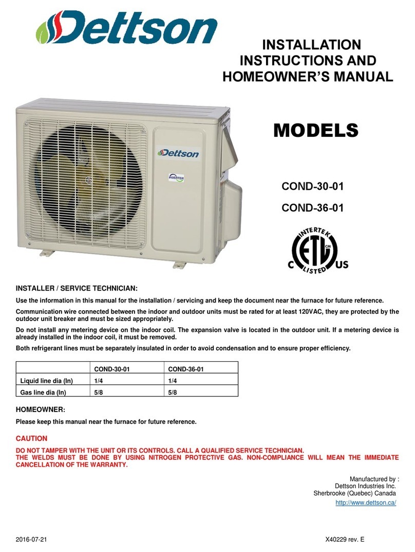
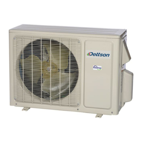
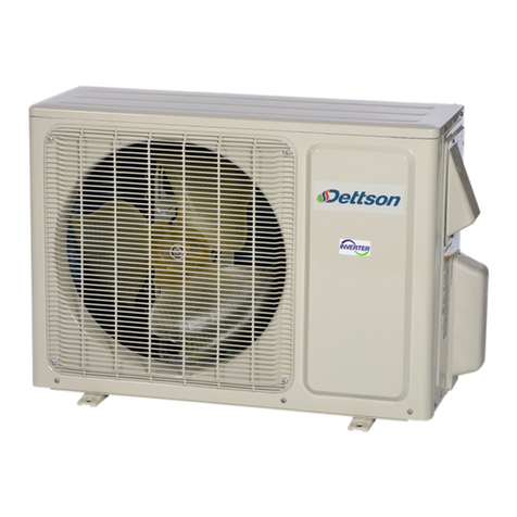
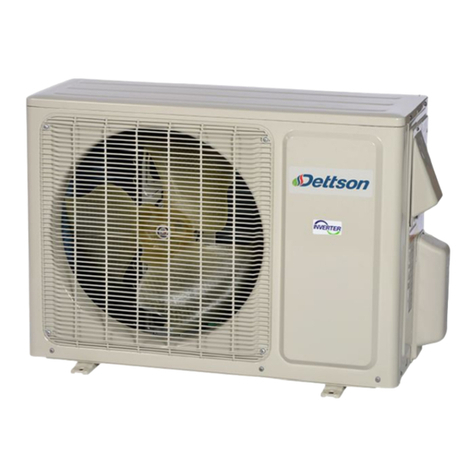
Dettson COND-09-01 Assembly instructions

2015-04-20 X40228 rev. B
APPENDIX 1.
INSTALLATION
INSTRUCTIONS AND
HOMEOWNER’S
MANUAL
Manufactured by :
Dettson Industries Inc.
3400, Industrial Boulevard
Sherbrooke (Quebec) Canada J1L 1V8
www.dettson.ca/
INSTALLER / SERVICE TECHNICIAN:
Use the information in this manual for the installation / servicing and keep the document near the furnace for future reference.
HOMEOWNER
:
Please keep this manual near the furnace for future reference.
CAUTION
DO NOT TAMPER WITH THE UNIT OR ITS CONTROLS. CALL A QUALIFIED SERVICE TECHNICIAN.
COND-09-01
COND-12-01
COND-18-01
COND-24-01
MODELS

2
2
QUICK SETUP
Simple startup using communicating thermostat
1. Turn off the breaker of the outdoor unit and the furnace
2. Connect COND1 and COND2 on the interface board to N(1) and 2 at the outdoor unit (See Figure 13 to Figure 15)
3. Connect the RJ-11 wire between the interface and the furnace control board (See Figure 13 to Figure 15)
4. Turn the outdoor unit “ON”
5. Turn the furnace “ON”
Make sure the unit is working properly
1. The Green LED on the interface board should be blinking once every two seconds
2. The Orange LED on the interface board should be blinking once every two seconds
3. The communicating thermostat will display “Heat_Pump_Found”
4. Set the thermostat to “COOL” mode and adjust the set point to a lower value than the actual room temperature
5. The furnace and the outdoor unit should start within 5 minutes
Modulating furnace
1. Connect the RJ-11 wire between the interface and the furnace control board
2. Connect the two wire coming from the outdoor unit
In this configuration, the interface board will gather information from both the outdoor unit and the furnace in order to adjust the fan
speed to the capacity of the outdoor unit
Legacy connection
1. Connect all the thermostat control wires to the interface board and the air handler control board (See Figure 27)
2. Make sure to connect the auxiliary heat outputs (W1 out and W2 out to the W1 and W2 inputs of the furnace)
3. Connect 1 and 2 on the interface board to N(1) and 2 at the outdoor unit (See Figure 27)
4. Set the dipswitches to the desired balance point (See Table 2)

3
TABLE
OF CONTENTS
APPENDIX 1.
............................................................. 1
1-
SAFETY PRECAUTIONS .......................................... 5
1.1-
Warning .................................................................... 5
1.2-
Caution ..................................................................... 5
1.3-
Specifications table................................................... 6
1.4-
Operation Charateristic Curves ................................ 7
1.5-
Capacity variation ratio according to temperature .... 8
1.6-
Noise criteria curve tables ........................................ 9
2-
CONSTRUCTION VIEWS ........................................ 10
3-
REGRIGERANT SYSTEM DIAGRAM ..................... 12
4-
SCHEMATIC DIAGRAMS........................................ 12
4.1-
Electrical diagrams ................................................. 12
4.2-
Printed circuit boards.............................................. 14
5-
FUNCTIONS AND CONTROL OUTDOOR UNIT .... 16
5.1-
Thermostat ............................................................. 16
5.1.1-
Communicating thermostat (R02P030) .......... 16
5.1.2-
Legacy thermostat.......................................... 16
5.2-
Balance point adjustment ....................................... 16
5.3-
Function & control................................................... 16
5.3.1-
09/12K Unit .................................................... 16
5.3.2-
18/24K Unit .................................................... 18
6-
INSTALLATION MANUAL ....................................... 21
6.1-
Notices for installation ............................................ 21
6.2-
Installation site instructions..................................... 21
6.3-
Installation site of outdoor unit ................................ 21
6.4-
Safety precautions for electric appliances .............. 21
6.5-
Grounding............................................................... 21
6.6-
Installation drawing................................................. 22
6.7-
Installation of indoor cooling coil............................. 22
6.7.1-
Multiposition coil............................................. 22
6.7.2-
Multiposition (field conversion) ....................... 24
6.7.3-
Condensate drain........................................... 24
6.8-
Installation of interface card.................................... 24
6.9-
Installation of connection pipe ................................ 25
6.10-
Installation of outdoor unit ...................................... 26
6.10.1-
Electrical wiring .............................................. 26
6.10.2-
Air purging and leakage test .......................... 26
6.10.3-
Outdoor unit condensate drainage ................. 26
6.10.4-
Check after installation and test operation......26
6.10.5-
Operation test .................................................26
7-
TROUBLESHOOTING..............................................27
7.1-
Precautions before performing inspection or repair 31
7.2-
Verification ..............................................................31
7.3-
Malfunction & status codes of the interface card
flashing leds ......................................................................32
7.4-
Malfunction & status codes of the outddor unit
flashing leds ......................................................................33
7.5-
Troubleshooting flow chart ......................................39
7.5.1-
Communication malfunction ...........................39
7.5.2-
Capacity charging malfunction (outdoor unit
malfunction)................................................................40
7.5.3-
IPM protection desynchronizing malfunction;
compressor overcurrent..............................................41
7.5.4-
Anti-high temperature, overload protection.....42
7.5.5-
Failure start up malfunction ............................43
7.5.6-
Compressor synchronism ...............................44
7.5.7-
Overload and discharge malfunction ..............45
7.5.8-
PFC (correction for power factor) malfunction 46
7.5.9-
Communication malfunction ...........................47
8-
REMOVAL PROCEDURE OF OUTDOOR UNIT .....48
9-
COMPONENTS AND REPLACEMENT PARTS......67
9.1-
Exploded vue 9/12k ................................................67
9.2-
Parts list 9/12k ........................................................68
9.3-
Exploded vue 18k ...................................................69
9.4-
Parts list 18K...........................................................70
9.5-
Exploded vue 24k ...................................................71
9.6-
Parts list 24K...........................................................72
APPENDIX 1.
RESISTANCE TABLE OF AMBIENT
TEMPERATURE SENSOR 15 K ...................................73
APPENDIX 2.
RESISTANCE TABLE OF TUBE
TEMPERATURE SENSOR 20 K ...................................74
APPENDIX 3.
RESISTANCE TABLE OF OUTDOOR
DISCHARGE TEMPERATURE SENSOR 50 K ............75
APPENDIX 4.
WARRANTY POLICY ........................76
4
LIST OF FIGURES
Figure 1: 9K Operation characteristic curves............................. 7
Figure 2: 12K Operation characteristics curves......................... 7
Figure 3: 18/24K Operation characteristics curves.................... 7
Figure 4: 9/12K Capacity ratio vs outdoor temperature ............. 8
Figure 5: 18/24K Capacity ratio vs outdoor temperature ........... 8
Figure 6: 9K Noise curves ......................................................... 9
Figure 7: 12K Noise curves ....................................................... 9
Figure 8: 18/24K Noise curve .................................................... 9
Figure 9: 9/12K dimensions..................................................... 10
Figure 10: 18K dimensions...................................................... 11
Figure 11: 24K dimensions...................................................... 11
Figure 12: refrigerant system diagram..................................... 12
Figure 13: 9/12K Electrical diagram ........................................ 12
Figure 14: 18K Electrical diagram ........................................... 13
Figure 15: 24K Electrical diagram ........................................... 13
Figure 16: 9/12K Circuit board................................................. 14
Figure 17: 18K Circuit board.................................................... 15
Figure 18: 24K Circuit board.................................................... 15
Figure 19: Installation schematic and clearances.................... 22
Figure 20: Multiposition configurations .................................... 23
Figure 21: Splashguard without front slope ............................. 23
Figure 22: Splashguard with front slope .................................. 24
Figure 23: Multiposition field conversion.................................. 24
Figure 24: Condensate drain ................................................... 24
Figure 25: Chinook gas furnace .............................................. 25
Figure 26: Supreme electric furnace ....................................... 25
Figure 27: Legacy furnace or air handler................................. 25
Figure 28: Tubing tightening.................................................... 26
Figure 29: Interface card ......................................................... 32
LIST OF TABLES
Table 1: Outdoor unit specifications...........................................6
Table 2: Dipswitch adjustment .................................................16
Table 3: Tubing torque tightening ............................................25
Table 4: Malfunction and status display of interface card ........32
Table 5: Malfunction and status display of outdoor unit
9/12K .......................................................................................33
Table 6: Malfunction and status display of outdoor unit
18/24K .....................................................................................35

5
1- SAFETY PRECAUTIONS
Installing, starting up, and servicing air conditioner can be hazardous due
to system pressure, electrical components, and equipment location, etc.
Only trained, qualified installers and service personnel are allowed to
install, start-up, and service this equipment. Untrained personnel can
perform basic maintenance functions such as cleaning coils. All other
operations should be performed by trained service personnel.
When handling the equipment, observe precautions in the manual and
on tags, stickers on the equipment. Follow all safety codes. Wear safety
glasses and work with gloves. Keep quenching cloth and fire
extinguisher nearby when brazing.
Read the instruction thoroughly and follow all warnings or cautions in
literature and attached to the unit. Always follow building codes and
current edition of national as well as local electrical codes.
Recognize the following safety information:
Warning: Incorrect handling could result in personal
injury or death
Caution: Incorrect handling may result in minor injury, or damage
to product or property
WARNING
1.1- WARNING
All electric work must be performed by a licensed technician according
to local regulations and the instructions given in this manual
⇒Before installing, modifying, or servicing system, main electrical
disconnect switch must be in the OFF position. There may be
more than 1 disconnect switch. Lock out and tag switch with a
suitable warning label;
⇒Never supply power to the unit unless all wiring and tubing are
completed, reconnected and checked;
⇒This system adopts dangerous electrical voltage. Incorrect
connection or inadequate grounding can cause personal injury
or death. Stick to the wiring diagram and all the instruction when
wiring;
⇒Have the unit adequately grounded in accordance with the local
electric codes;
⇒Have all wiring connected tightly. Loose connection may lead to
overheating and a possible fire hazard.
All installation or repair work shall be performed by your dealer or a
specialized subcontractor as there is the risk of fire, electric shock,
explosion or injury.
⇒Make sure the outdoor unit is installed on a stable, level surface
with no accumulation of snow, leaves, or trash beside;
⇒Avoid contact between refrigerant and fire as it generates
poisonous gas;
⇒Apply specified refrigerant only. Never have it mixed with any
other refrigerant. Never have air remain in the refrigerant lines
as it may lead to rupture and other hazards;
⇒Make sure no refrigerant gas is leaking out when installation is
completed;
⇒Should there be refrigerant leakage, the density of refrigerant in
the air shall in no way exceed its limited value, or it may lead to
explosion;
⇒Keep your fingers and clothing away from any moving parts;
⇒Clear the site after installation. Make sure no foreign objects are
left in the unit;
⇒Always ensure effective grounding for the unit.
CAUTION
1.2- CAUTION
⇒Never install the unit in a place where a combustible gas might
leak, or it may lead to fire or explosion;
⇒Provide a ground fault interrupter (GFI) when it is installed in a
watery place;
⇒Never wash the unit with water
⇒Handle unit transportation with care. The unit should not be
carried by only one person if it is more than 20 kg;
⇒Never touch the heat exchanger fins with bare hands;
⇒Never touch the compressor or refrigerant piping without
wearing glove;
⇒Make sure that the air handler filter is clean;
⇒Should any emergency occur, stop the unit and disconnect the
power immediately;
⇒Properly insulate ALL refrigerant tubing from outdoor units to the
interior cooling coil to prevent water dripping.

6
6
1.3- SPECIFICATIONS TABLE
Table 1: Outdoor unit specifications
COND-09-01
COND-12-01
COND-18-01
COND-24-01
Rated voltage
V~
Rated frequency
H
Phase
Btu/h
9000(3500~9600)
12000(3100~13000)
18000(4600~20000)
24000(6800~26000)
Btu/h
9800(2200~11000)
13000(2400~14000)
19000(3400~20000)
25000(7500~26000)
W
600(330~1200)
882(380~1300)
1500(180~2450)
2000(450~3050)
W
650(100~1250)
960(100~1350)
1580(232~2500)
2090(450~3300)
A
5.7
6
7.36/6.65
9.1
A
7
7.5
7.75/7.01
11.36
W
1300
1400
2500
3200
A
9
9
11.1
16
(Btu/h)/W
14.5
12.8
12
13
3.8
3.5
3.5
3.3
27
25
21
21
9
9
9.8
10
A
13.8
13.8
27
40
A
3.2
3.2
8.4
12
W
860
860
1245
2450
° F (°C)
° F (°C)
° F (°C)
Condenser pipe diameter
inch(cm)
ɸ0.31(0.79)
ɸ0.3(0.76)
ɸ0.38(0.97)
ɸ0.31(0.79)
inch
2.5-0.06
2.5-0.06
2-0.06
3-0.06
cm
6.35-0.15
6.35-0.15
5.08-0.15
7.62-0.15
inch
30x2.2x21.7
30x2.2x21.7
32x1.7x26.0
37.5x2.25x30
cm
76.2x5.59x55.12
76.2x5.59x55.12
81.28x4.32x66.04
95.25x5.16x76.2
rpm
600/750/850
600/750/850
700
780/390
W
40
40
60
90
A
0.18
0.18
0.28
n/a
CFM
1177
1177
1883.2
2354
inch(cm)
ɸ17.5(44.45)
ɸ17.5(44.45)
ɸ20.5(52.07)
ɸ21.7(55.12)
MPa
4.3
4.3
4.3
3.8
MPa
2.5
2.5
2.5
1.2
dB (A)
49
49
56
56
dB (A)
59
59
66
66
inch
35.4x23.5x14.9
35.4x23.5x14.9
37.6x27.6x15.6
38.6x31.1x16.8
cm
89.92x59.69x37.85
89.92x59.69x37.85
95.50x70.10x39.62
98.04x79x42.68
inch
37.2x24.8x16.4
37.2x24.8x16.4
40.4x28.9x17.9
42.7x33.1x19.1
cm
94.49x62.99x41.66
94.49x62.99x41.66
102.62x73.41x45.47
108.46x84.07x48.51
inch
37.3x25.4x16.5
37.3x25.4x16.5
40.5x29.5x18.0
42.8x33.7x19.2
cm
94.74x64.52x41.91
94.74x64.52x41.91
102.87x74.93x45.72
108.71x85.60x48.77
lb
86
87.1
110.3
154.3
lb
90.4
91.5
116.9
165.3
o
45.9
45.9
56.5
88.2
ft
24.6
24.6
24.6
24.6
o /ft.
0.2
0.2
0.5
0.5
inch(cm)
ɸ 0.25(0.635)
ɸ 0.25(0.635)
ɸ 0.25(0.635)
ɸ 0.25(0.635)
inch(cm)
ɸ 0.50(127)
ɸ 0.50(127)
ɸ 0.625(1.5875)
ɸ 0.625(1.5875)
ft
32.8
32.8
32.8
32.8
ft
49.2
65.6
82
82
Max distance length
Liquid pipe outer diameter
Gas pipe outer diameter
Max distance height
Refrigerant charge
Connection pipe length
Connection pipe gas additional charge
Net weight
Gross weight
Refrigerant
R410A
Dimensions (WxHxD)
Dimensions of carton box(WxHxD)
Dimensions of package(WxHxD)
Permissible excessive operating
Sound pressure level
Sound power level
Moisture protection
IP24
Permissible excessive operating
Climate type
T1
Isolation
I
Fan diameter
Defrosting method
Automati defrosting
Fan motor RLA
Air flow volume
Fan type
Axial-flow
Condenser coil dimensions (LxDxW)
Fan motor speed
Fan motor power output
Condenser form
Aluminum fins- opper tube
Condenser rows-fin gap
Heating operation ambient temperature range
-4~86(-20~30)
5~75.2(-15~24)
Set temperature range
60.8~86(16-30)
Cooling operation ambient temperature range
0~118.4(-18~48)
50~118.4(10~48)
Compressor RLA
Compressor power input
Throttling method
Ele troni expansion valve
Compressor type
Rotary
Compressor LRA
COP *
SEER *
HSPF *
Rated current
EER *
Heating power input (min~max)
Cooling current input
Heating current input
Cooling power input (min~max)
Model
Power
suppl
y
208/230
Rated input
60
1
Cooling capacity (min~max)
Heating capacity (min~max)

7
7
1.4- OPERATION CHARATERISTIC CURVES
Figure 1: 9K Operation characteristic curves
Figure 2: 12K Operation characteristics curves
Figure 3: 18/24K Operation characteristics curves

8
8
1.5- CAPACITY VARIATION RATIO ACCORDING TO TEMPERATURE
Figure 4: 9/12K Capacity ratio vs outdoor temperature
Figure 5: 18/24K Capacity ratio vs outdoor temperature

9
9
1.6- NOISE CRITERIA CURVE TABLES
Figure 6: 9K Noise curves
Figure 7: 12K Noise curves
Figure 8: 18/24K Noise curve

10
10
2- CONSTRUCTION VIEWS
Figure 9: 9/12K dimensions

11
11
Figure 10: 18K dimensions
Figure 11: 24K dimensions

12
12
3- REGRIGERANT SYSTEM DIAGRAM
Figure 12: refrigerant system diagram
*
Properly insulate ALL refrigerant tubing from outdoor units to the interior cooling coil to prevent water dripping.
4- SCHEMATIC DIAGRAMS
4.1- ELECTRICAL DIAGRAMS
Figure 13: 9/12K Electrical diagram

13
13
Figure 14: 18K Electrical diagram
Figure 15: 24K Electrical diagram

14
14
4.2- PRINTED CIRCUIT BOARDS
Figure 16: 9/12K Circuit board

15
15
Figure 17: 18K Circuit board
Figure 18: 24K Circuit board

16
5- FUNCTIONS AND CONTROL
OUTDOOR UNIT
5.1- THERMOSTAT
5.1.1- Communicating thermostat (R02P030)
The unit must be used with the Dettson communicating thermostat
(R02P030) in order to work as a fully modulating unit. In this case, the
interface board (R99G025) will be able to gather information from the
outdoor unit, the furnace and the thermostat making this integrated
system very easy to install and increased home owner comfort. The
indoor blower speed will be determined by various factors including
outdoor temperature, compressor speed and demand from the
thermostat. The balance point (temperature at which the unit will switch
from heat pump heating to auxiliary heat) will be settable through the
thermostat. If is unit is destined to be used as a cooling system only, the
heat pump feature can also be disabled altogether from the
communicating thermostat.
For more details refer to the manual provided with the thermostat.
Auxiliary Heating
Heat pump Disable
This feature is applicable only in the heat pump mode. When this feature
is selected, the thermostat will switch to electric heat and shut off the
compressor when the outside temperature falls below the HP balance
point. In the Thermostat User Menu, select the temperature which can
be between -15°C (5°F) to 10°C (50°F).
Dual Fuel Disable
This feature is applicable only in the heat pump mode. When this feature
is selected, the thermostat will switch to fossil fuel heat and shut off the
compressor when the outside temperature falls below the DF balance
point. In the Thermostat User Menu, select the temperature which can
be between -15°C (5°F) to 10°C (50°F).
5.1.2- Legacy thermostat
Shall the unit be controlled by a one or two stage legacy thermostat, the
unit will only be able to run as a one or two stage unit. Hence, the indoor
blower speed will only be controlled by the air handler, leading to a fixed
air flow operation. In this configuration, the balance point can be set
using the dipswitches S1-1 to S1-4 (see Table 2). The Auxiliary heat or
heat pump function can also be disabled using those same switches.
5.2- BALANCE POINT ADJUSTMENT
When the dipswitch bank is set accordingly, the interface board will
modify the heat source in function of the outdoor temperature. The
outdoor unit will send the temperature reading through the serial
communication wires (COND1 and COND2), no need to install a
separate temperature sensor. The unit will heat using the heat pump until
the outdoor temperature goes below the balance point that was set
according to the dipswitch table below.
Table 2: Dipswitch adjustment
DIP1
-
1
DIP1
-
2
DIP1
-
3
DIP1
-
4
Balance point
OFF OFF OFF OFF Heat pump heat only
ON
OFF OFF OFF -10°F (-23°C)
OFF
ON
OFF OFF -5°F (-21°C)
ON
ON
OFF OFF 0°F (-18°C)
OFF OFF
ON
OFF 5°F (-15°C)
ON
OFF
ON
OFF 10°F (-12°C)
OFF
ON
ON
OFF 15°F (-9°C)
ON
ON
ON
OFF 20°F (-7°C)
OFF OFF OFF
ON
25°F (-4°C)
ON
OFF OFF
ON
30°F (-1°C)
OFF
ON
OFF
ON
35°F (2°C)
ON
ON
OFF
ON
40°F (4°C)
OFF OFF
ON
ON
45°F (7°C)
ON
OFF
ON
ON
50°F (10°C)
OFF
ON
ON
ON
55°F (13°C)
ON
ON
ON
ON
AUX heat only
5.3- FUNCTION & CONTROL
5.3.1- 09/12K Unit
5.3.1.1 Temperature Parameters
•Indoor thermostat temperature (
)
•Indoor ambient temperature (
.)
Note:
is determined by indoor and outdoor units. If indoor
unit controls temperature compensation,
is determined by
the value sent to outdoor unit by indoor unit; If it is not controlled by indoor
unit,
will be 3°C (37.4°F) as default.
5.3.1.2 Basic Functions
Once energized, in no case should the compressor be restarted within
less than 3 minutes. In the situation that memory function is available,
for the first energization, if the compressor is at stop before de-
energization, the compressor will be started with a 3-minute lag; and
once started, the compressor will not be stopped within 6 minutes
regardless of changes in room temperature;
1. Cooling mode
Working conditions and process of cooling
(1) When
.≥
, the unit will enter cooling operation.
In that case, the outdoor fan and compressor will operate and
the indoor fan will run at preset speed ;
(2) When
, and compressor has
continuously operated at frequency lower than 15Hz (not
including 15Hz) for 17 minutes, if
the compressor will stop operation;
(3) When
, compressor will stop
operations and in 30s later, outdoor fan will stop operation;
(4) When
, the unit will keep
its previous operation.
Protections
•Antifreeze protection
Under cooling and dehumidifying mode, 6 minutes after the compressor
is started:
(1) If
), the compressor will operate at
reduced frequency;
(2) If
), is detected for 3 minutes
continuously, the compressor will stop, and after 30 seconds,
the outdoor fan will stop; and under cooling mode, the indoor
fan and the swing motor will remain at the original state;
(3) If
), and the compressor has remained at
OFF for at least 3 minutes, the compressor will resume its
original operation state.
•Total current up and frequency down protection
(1) When total current
≤6A, increasing frequency is allowed;
(2) When total current
≥7A, increasing frequency is
prohibited;
(3) When total current
≥8A, the unit operates by decreasing
frequency.
(4) When total current
≥9A, the compressor stops operation,
and indoor fan will stop operation after 30s.
2. Heating Mode
Working conditions and process of heating
(1) When
, the
unit will enter heating operation. In that case, compressor,
outdoor fan and 4-way valve will operate at the same time.

17
17
(2) When
, the unit will keep its previous
operation status.
(3) When
,
compressor will stop operation and in 30s later, the outdoor
fan will stop operation;
(4) When the unit is turned off at heating mode, or changes to
another mode from heating mode, the 4-way valve will be de-
energized in 2 minutes later after compressor stops operation
(the compressor is operating during heating mode).
(5) When
, compressor will stop
operation immediately and outdoor fan will stop operation in
30s later.
(6) When the compressor is operating, or changing to heating
from cooling, the 4-way valve will be energized in 2-3 minutes
later.
Condition and process of defrost
(1) When
and compressor has
operated for a cumulated time of 3 hours, if
the unit will enter defrosting mode.
Note: the time will be cleared when
compressor has been started up after changing to cooling
mode and defrosting has finished. The time will not be cleared when the
unit stops when reaching temperature point, or for protection, changing
to fan mode, etc).
(2) When heating has operated for continuous 45 minutes, or for
an accumulated 90 minutes, the unit will enter defrosting mode
in 3 minutes after meeting any condition below;
a.
;
b.
,
c.
;
d. ),
e. ,
After energization, for the first defrosting, ; if it is not the
first time of defrosting, will be determined by
when quitting defrosting last time; if
, ; if
.
(3) During defrosting, if operation time for compressor does not
reach 3min, the defrosting will not be entered in the
subsequent 2 hours. At that time, compressor stops operation
and in 30s later, the outdoor fan will stop operation; in another
30s, 4-way valve will stop operation; in 30s later, compressor
will increase its frequency for defrosting. When defrosting lasts
for 450s, or , compressor will
decrease its frequency. In 30s later, compressor will stop
operation; in another 30s, 4-way valve will be started up. In
60s later, compressor and outdoor fan will operate. Frequency
for defrosting is 85Hz.
Protections : Total current up and frequency down
When total current , increase frequency is allowed; when
total current , increasing frequency is prohibited; when total
current , the unit operates by decreasing frequency. When
total current the compressor stops operation, and indoor
fan will stop operation after 30s.
3. Common Protection Functions and Fault display under
COOL and HEAT Modes
Overload protection
: measured temperature of outdoor heat exchanger under cooling
mode; and measured temperature of indoor heat exchanger under
heating mode.
(1) Cooling overload
a. If the unit will return to its
original state.
b. If , frequency rise is not
allowed.
c. If ), the compressor will run
at reduced frequency.
d. If , the compressor will
stop.
(2) Heating overload
a. If the unit will return to n its
original operation sate.
b. If , frequency rise is not
allowed.
c. If , the compressor will run
at reduced frequency.
d. If , the compressor will stop
and the indoor fan will blow residual heat and then
stop.
Exhaust temperature protection of compressor
(1) If exhaust temperature ≥98°C (208.4°F), frequency is not
allowed to rise.
(2) If exhaust temperature ≥103°C (217.4°F), the compressor will
run at reduced frequency.
(3) If exhaust temperature ≥110°C (230°F), the compressor will
stop.
(4) If exhaust temperature ≤90°C (194°F) and the compressor has
stayed at stop for at least 3 minutes, the compressor will
resume its operation.
Communication fault
If the unit fails to receive correct signals for durative 3 minutes,
communication fault can be justified and the whole system will stop.
Module protection
Under module protection mode, the compressor will stop. When the
compressor remains at stop for at least 3 minutes, the compressor will
resume its operation. If module protection occurs six times in succession,
the compressor will not be started again.
Overload protection
If temperature sensed by the overload sensor is over 115°C (239°F), the
compressor will stop and the outdoor fan will stop with a time lag of 30
seconds. If temperature is below 95°C (203°F), the overload protection
will be relieved.
DC bus voltage protection
If voltage on the DC bus is below 150V or over 420V, the compressor
will stop and the outdoor fan will stop with a time lag of 30 seconds. When
voltage on the DC bus returns to its normal value and the compressor
has stayed at stop for at least 3 minutes, the compressor will resume its
operation.
5.3.1.3 Control of outdoor electric Heating Band
If not in heating mode or temp sensor has malfunction, electric heating
bands of compressor and of condenser will stop operation, otherwise,
the below control logic will be followed.
1. Control of Compressor electric heating Band
a. Conditions for startup: the compressor is off and
meanwhile outdoor ambient temp≤-5°C (23°F);

18
18
b. Conditions for turning off: it will be turned off when
meeting any condition below:
•Compressor is operating
•Compressor is turned off and meanwhile
outdoor ambient temp ≥-2.2°C (28°F);
c. Outdoor ambient temp sensor has malfunction and
electric heater band stops operation.
2. Control of Electric Heater Band of Condenser
a. When , electric
heater band of condenser will operate.
b. During defrosting process, electric heater band of
chassis will operate in 3 min after compressor starts
operating. When compressor has operated for 3 min
and , electric heater
band will stop operating.
c. When , electric
heater band of condenser will not operate.
d. When
electric heater band of condenser will
keep its previous status.
When outdoor ambient temp sensor has malfunction, electric heater
band stops operation; once electric heater stops operation, it has to
wait at least 2 minutes before it can be restarted up again.
5.3.2- 18/24K Unit
Interface Board
5.3.2.1 Temperature Parameters
•Indoor preset temperature ()
•Indoor ambient temperature (
5.3.2.2 Basic functions
Once the compressor is energized, there should be a minimum interval
of 3 minutes between two start-ups. But if the unit is de-energized and
then energized, the compressor can restart within 3 minutes.
1. Cooling mode
Cooling conditions and process
(1) When , the unit starts cooling operation. In
this case, the compressor and the outdoor fan operate.
(2) When the compressor and
the outdoor fan stop.
(3) When Tpreset-3°C (37.4°F)<Tamb.<Tpreset, the unit will
maintain its previous running status.
When outdoor unit has malfunction and stops for protection,
indoor unit will keep previous operation status.
2. Heating mode
Heating conditions and process
(1) When , the unit starts heating
operation. In this case, compressor and outdoor fan operate
simultaneously; the indoor fan operates at cold-air prevention
mode.
(2) When ), the compressor and
outdoor fan stop operation; the indoor fan blows residual
heat.
(3) When
the unit will maintain its previous running status.
Defrosting and oil return
When receiving the signal of defrosting and oil return, indoor fan will
stop operation. During defrosting, oil return and 5 minutes after quit, all
indoor pipe temperature sensors will not be detected.
Blow residual heat
In heating mode, when temperature reaches the set temperature, the
compressor and outdoor fan will stop.
When the unit is in heating mode, and the compressor and indoor fan
are operating. If the unit is turned off, the compressor and outdoor fan
will stop. Indoor unit will operate at low speed for 10 seconds and then
the unit will be turned off.
Outdoor unit
5.3.2.1 Compensation function of input parameters
According to the structure of wall-mounting unit and the comfortability
for operation, when the compressor is at OFF status, indoor ambient
temperature is higher than set temperature under heating mode.
5.3.2.2 Outdoor discharge temperature sensor
For ensuring the safety and reliability of operation, please insert the
outdoor discharge temperature sensor into the corresponding
temperature sensor bushing to make sure that the control system can
detect system discharge temperature accurately. Otherwise, the unit
will stop operation and it displays malfunction of discharge temperature
sensor (discharge temperature sensor has not been inserted well).
5.3.2.3 Cooling mode
Working condition and process for cooling
(1) If compressor is at OFF status, and (
)≤0°C (0°F), the unit operates
in cooling mode;
(2) During cooling operation, if 0°C (0°F)≤(
)<3°C (5.4°F), the unit still
operates in cooling mode;
(3) During cooling operation, if 3°C (5.4°F)≤(
), the unit stops
operation when reaching the temperature point in cooling.
5.3.2.4 Defrosting control (heating mode)
(1) If it turns to defrosting time and it detects that the defrosting
temperature is satisfied for 3 minutes successively, the unit
turns into defrosting process.
(2) Defrosting-starting: compressor stops operation and restart it
up after 55s delayed.
(3) Defrosting-ending: compressor stops operation and it starts
up after 55s delayed.
(4) When any of below defrosting-ending conditions is satisfied,
the unit will quit from defrosting operation :
•
for defrosting;
•Defrosting operation time is reached at
.
5.3.2.5 Control of compressor
(1) Frequency of compressor controls the frequency according to
the relation between ambient temperature and set
temperature, and the change speed of ambient temperature.
(2) Under cooling, and heating mode, compressor will be started
up after outdoor fan is started for 5s.
(3) At the OFF status, the operation stops immediately because
of protection and switchover to fan mode.
(4) Under each mode: once the compressor is started up, it can
be stopped only after operation.
(5) Under each mode: once the compressor is stopped, it can be
restarted up only after 3 minutes delayed.

19
19
5.3.2.6 Control of outdoor fan
(1) When turn off the unit by thermostat, stop operation because
of protection or stop operation after reaching the temperature
point, outdoor can stop operation only after the compressor is
stopped for 1min;
(2) Under fan mode: outdoor fan stops operation.
(3) Defrosting-starting: enter into defrosting. Outdoor fan stops
operation after compressor stops for 50s.
(4) Defrosting-ending: quit defrosting. When the compressor
stops operation, the outdoor fan operates.
5.3.2.7 Control of 4-way valve
(1) 4-way valve status under cooling and fan modes: OFF;
(2) When the unit turned on and operated in heating mode, the
4-way valve is energized immediately;
(3) If turn off unit or switch to other mode in heating mode, the
4-way valve is de-energized after the compressor stops for
2min;
(4) When the unit is turned off because of each protection, the 4-
way valve is de-energized after 4min delayed;
(5) Defrosting-starting: enter into defrosting. After the
compressor stops for 50s, the 4-way valve will be de-
energized;
(6) Defrosting-ending: quit defrosting. After the compressor
stops for 50s, the 4-way valve is energized.
5.3.2.8 Freeze protection
(1) Under cooling mode, if it is detected that
0°C
(32°F) for 3min successively, the unit will stop operation due
to freeze protection. If
, and compressor stops for 3min, the complete unit
can resume operation;
(2) Under cooling mode, if
6°C (42.8°F), the
operation frequency of compressor may increase or
decrease;
(3) If the unit is stopped because of freeze protection for 6 times
successively, it cannot resume operation automatically and
the malfunction will be displayed continuously, which can
only be resumed by turning thermostat to OFF on heat
setting. During operation, if operation time of compressor is
over, the times of stop operation because of freeze protection
will be cleared. If turn off the unit or switch to fan/heating
mode, malfunction and times of malfunction is eliminated
immediately.
5.3.2.9 Overload protection
(1) Overload protection under cooling mode: if
, the unit stops
operation because of overload in cooling; if
and the compressor has
stopped for 3min, the complete unit can resume operation.
(2) Under cooling mode, if
, the frequency of compressor may increase or
decrease;
(3) Overload protection under heating mode: if
, the unit stops
operation because of overload in heating; if
and the compressor has
stopped for 3min, the complete unit can resume operation.
(4) Under heating mode, if
, operation frequency of compressor may increase
or decrease;
(5) If the unit is stopped because of overload protection for 6
times successively, it cannot resume operation automatically
and the malfunction will be displayed continuously, which can
only be resumed by turning the thermostat to OFF or cooling
mode. During operation, if operation time of compressor is
over, the times of stop operation because of overload
protection will be cleared. If turn the thermostat to OFF or
switch to fan/cooling mode, malfunction and times of
malfunction is eliminated immediately.
5.3.2.10 Discharge temperature protection of compressor
(1) If
, the unit stops
operation because of discharge protection; if
and compressor has stopped for
3 min, the complete unit can resume operation;
(2) If
, operation
frequency of compressor may decrease or increase;
(3) If the unit is stopped because of discharge protection of
compressor for 6 times successively, it cannot resume
operation automatically, it can only be resumed by pressing
ON/OFF button. During operation, if operation time of
compressor is over, the times of stop operation because of
discharge protection will be cleared. If turn off the unit, or
switch to fan mode, malfunction and times of malfunction is
eliminated immediately.
5.3.2.11 Current protection function
(1) If 13A≤
, operation frequency of compressor may
decrease or increase;
(2) If 17A≤
, the system will stop operation because of
overcurrent; the complete unit can resume operation only
after the compressor stops for 3min;
(3) If the unit is stopped because of overcurrent for 6 times
successively, it cannot resume operation automatically, it can
only be resumed by turning thermostat to OFF setting. During
operation, if operation time of compressor is over, the times
of stop operation because of overcurrent protection will be
cleared.
5.3.2.12 Voltage drop protection
During operation of compressor, if the voltage is decreasing quickly, the
system may stop operation and voltage drop malfunction is caused.
3min later, the system will be restarted up automatically.
5.3.2.13 Communication malfunction
When it has not received the correct signal from indoor unit from 3min,
the unit will stop operation; communication malfunction is eliminated
and compressor has stopped for 3min, the complete unit can resume
operation.
5.3.2.14 IPM (Intelligent Power Model) protection
After compressor is turned on, if the overcurrent happens for IPM, or
control voltage is too low because of abnormal causes, IPM will detect
module protection signal immediately. Once it detected the module
protection signal, the unit will stop operation because of module
protection. If module protection is resumed and compressor has
stopped for 3min, the complete unit will resume operation. If the unit is
stopped because of module protection for 3 times successively, the unit
cannot resume operation automatically unless thermostat is turned to
OFF setting. If the operation time for compressor is over, the times of
stop operation because of module protection will be cleared.
5.3.2.15 Overheat protection of module
(1) If
, the
operation frequency of compressor may decrease or
increase;
(2) If
, the system will
stop operation for protection. If

20
20
and compressor has
stopped for 3minm the complete unit will resume operation.
(3) If the unit is stopped because of overheating of compressor
module for 6 times successively, it cannot resume operation
automatically, it can be only resumed by turning thermostat
to OFF setting. During operation, if operation time of
compressor is over, the times of stop operation because of
compressor overheating protection will be cleared. If turn off
the unit, or switch to fan mode, times of malfunction is
eliminated immediately.
5.3.2.16 Overload protection of compressor
(1) If it detected that the overload switch for compressor is open
for 3min successively, the complete unit will stop operation
for protection;
(2) If overload protection is resumed and compressor has
stopped for 3min, the complete unit can resume operation;
(3) If the unit stops operation because of overload protection for
compressor for 3 times successively, it cannot resume
operation automatically, it can only be resumed by turning
thermostat to OFF setting. After compressor has operated for
30min, overload protection times for compressor will be
eliminated.
This manual suits for next models
3
Table of contents
Other Dettson Air Conditioner manuals

Dettson
Dettson COND-30-01 Quick start guide

Dettson
Dettson COND-OCD-09 Assembly instructions

Dettson
Dettson COND-30 Assembly instructions

Dettson
Dettson COND-ELD-09 Quick start guide

Dettson
Dettson Atmos MHD-18 Installation instructions

Dettson
Dettson DCAH Series Assembly instructions

Dettson
Dettson COND-UHD-09 Assembly instructions
Popular Air Conditioner manuals by other brands

York
York YNKFZC024-055BAADAFX owner's manual

Mitsubishi Electric
Mitsubishi Electric PLA-SP BA Series Operation manual

Cruisair
Cruisair Zephyr Installation and operation manual

Daikin
Daikin VRV III REMQ8P8Y1B installation manual

Technibel
Technibel KPAFP125R5IA Series instruction manual

Haier
Haier AS072AIAAA Operation manual