DEUTA Controls EnoPuck CO2 User manual

Manual Page 1 of 32
© DEUTA Controls GmbH Paffrather Str. 140, 51465 Bergisch Gladbach Tel.:+49 2202 285 57- 61
23.11.2022 Hauptstraße 76, 32479 Hille Tel: +49 5734 51466 - 0
Technical data might change info@deuta-controls.de; www.deuta-controls.net Fax:+49 5734 51466 - 28
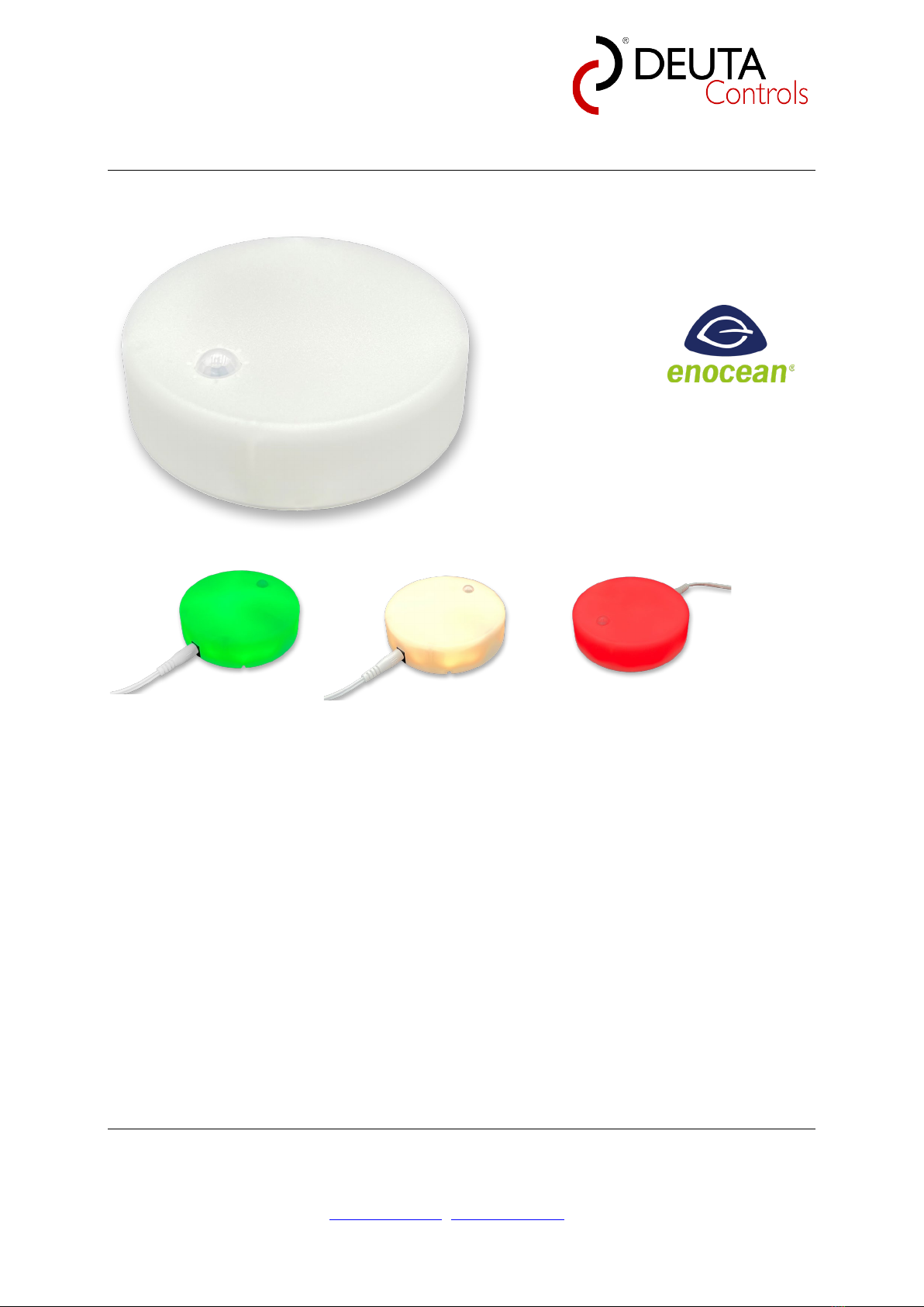
EnoPuck®CO2
EnoPuck®CO2 NOISE
EnoPuck®CO2 WALL
EnOcean Sensor and RGB-LED for CO2 and
sound pressure level measurement
EnOcean / 902 MHz / FCC
Version 1.02

EnoPuck®CO2 / CO2 NOISE / CO2 WALL
Product manual Page 2 of 32
© DEUTA Controls GmbH Paffrather Str. 140, 51465 Bergisch Gladbach Tel.:+49 2202 285 57- 61
23.11.2022 Hauptstraße 76, 32479 Hille Tel: +49 5734 51466 - 0
Technical data might change info@deuta-controls.de; www.deuta-controls.dnet Fax:+49 5734 51466 - 28
© 2022 DEUTA Controls GmbH
All rights reserved
This manual, including all figures and illustrations, is copyright-protected. Any further use of
this manual by third parties that violate pertinent copyright provisions is prohibited.
Reproduction, translation, electronic and phototechnical filing/archiving (e.g., photocopying)
as well as any amendments require the written consent of DEUTA Controls GmbH, Bergisch
Gladbach, Germany. Non-observance will involve the right to assert damage claims.
DEUTA Controls GmbH
Paffrather Straße 140
51465 Bergisch Gladbach
Phone:+49 2202 28557-61
Fax: +49 2202 28557-79
E-Mail: info@deuta-controls.de
Web: www.deuta-controls.net
Every conceivable measure has been taken to ensure the accuracy and completeness of this
documentation. However, as errors can never be fully excluded, we always appreciate any
information or suggestions for improving the documentation.
E-Mail: info@deuta-controls.de

EnoPuck®CO2 / CO2 NOISE / CO2 WALL
Product manual Page 3 of 32
© DEUTA Controls GmbH Paffrather Str. 140, 51465 Bergisch Gladbach Tel.:+49 2202 285 57- 61
23.11.2022 Hauptstraße 76, 32479 Hille Tel: +49 5734 51466 - 0
Technical data might change info@deuta-controls.de; www.deuta-controls.dnet Fax:+49 5734 51466 - 28
Table of contents
1.1 About this manual ................................................................................................... 6
1.2 Notes about this Manual.......................................................................................... 6
1.3 Validity of this documentation.................................................................................. 7
1.4 Symbols / Information on safety .............................................................................. 8
2Information on product safety ......................................................................................... 9
2.1 Intended use ........................................................................................................... 9
2.2 Predictable incorrect application.............................................................................10
2.3 Qualification of personnel.......................................................................................11
2.3.1 EnoPuck®CO2 / EnoPuck®CO2 NOISE.........................................................11
2.3.2 EnoPuck®CO2 WALL .....................................................................................11
3Disposal ........................................................................................................................12
4Device description .........................................................................................................13
4.1 Functionality...........................................................................................................13
4.2 Multi-Sensor with EnOcean interface .....................................................................13
4.3 RGB-LED with local or remote control....................................................................13
4.4 Factory settings......................................................................................................14
4.5 External product interface ......................................................................................14
4.5.1 EnoPuck®CO2 / EnoPuck®CO2 NOISE.........................................................14
4.5.2 EnoPuck®CO2 WALL .....................................................................................15
4.6 Observe intended use ............................................................................................16
4.7 Observe statutory provisions for operating frequency range...................................16
4.8 Non-conduction mounting surface..........................................................................16
5Technical data...............................................................................................................17
5.1 Communication / EnOcean wireless interface ........................................................17
5.2 Sensor: CO2 concentration ....................................................................................17
5.3 Sensor: Rel. humidity (RH).....................................................................................17
5.4 Sensor: Temperature .............................................................................................17
5.5 Sensor: Ambient light / brightness..........................................................................18
5.6 Sensor: Sound pressure level (only EnoPuck® CO2 NOISE).................................18

EnoPuck®CO2 / CO2 NOISE / CO2 WALL
Product manual Page 4 of 32
© DEUTA Controls GmbH Paffrather Str. 140, 51465 Bergisch Gladbach Tel.:+49 2202 285 57- 61
23.11.2022 Hauptstraße 76, 32479 Hille Tel: +49 5734 51466 - 0
Technical data might change info@deuta-controls.de; www.deuta-controls.dnet Fax:+49 5734 51466 - 28
5.7 Sensor: Motion / PIR ..............................................................................................18
5.8 User interfaces .......................................................................................................18
5.9 Housing / connection technology............................................................................18
5.10 Power supply..........................................................................................................18
5.11 Environmental conditions .......................................................................................19
5.12 Dimensions and weight ..........................................................................................19
5.13 Approvals ...............................................................................................................19
5.14 Standards and guidelines.......................................................................................19
6Functional description in detail ......................................................................................20
6.1 Basic device description.........................................................................................20
6.2 Send Teach-In telegrams .......................................................................................20
6.2.1 CO2 Teach-In (A5-09-04)................................................................................20
6.2.2 PIR Teach-In (A5-07-01) .................................................................................21
6.2.3 Brightness Teach-In (A5-08-01) ......................................................................21
6.2.4 Sound Pressure Level Teach-In (D2-14-52) ....................................................21
6.3 Transmitting data ...................................................................................................21
7Service / CO2 sensor calibration ...................................................................................22
7.1 Re-calibration of EnoPuck®CO2 / EnoPuck®CO2 NOISE .....................................22
7.2 Re-calibration of EnoPuck®CO2 WALL .................................................................23
7.2.1 Room with windows that can be opened .........................................................23
7.2.2 Room without windows that can be opened ....................................................24
8Device labels.................................................................................................................25
8.1 EnoPuck®CO2 / FCC (AL-602-01-092) / Part nr. 12562 ........................................26
8.1.1 Device / certification data: ...............................................................................26
8.1.2 Label 1: ...........................................................................................................26
8.1.3 Label 2: ...........................................................................................................26
0x0012345 ...................................................................................................................26
8.2 EnoPuck®CO2 NOISE / FCC (AL-602-02-902) / Part nr. 12563 ............................27
8.2.1 Device / certification data: ...............................................................................27
8.2.2 Label 1: ...........................................................................................................27
8.2.3 Label 2: ...........................................................................................................27

EnoPuck®CO2 / CO2 NOISE / CO2 WALL
Product manual Page 5 of 32
© DEUTA Controls GmbH Paffrather Str. 140, 51465 Bergisch Gladbach Tel.:+49 2202 285 57- 61
23.11.2022 Hauptstraße 76, 32479 Hille Tel: +49 5734 51466 - 0
Technical data might change info@deuta-controls.de; www.deuta-controls.dnet Fax:+49 5734 51466 - 28
0x00012345 .................................................................................................................27
8.3 EnoPuck®CO2 WALL / FCC (AL-602-04-902) / Part. Nr. 12564 ............................28
8.3.1 Device / certification data: ...............................................................................28
8.3.2 Label 1: ...........................................................................................................28
8.3.3 Label 2: ...........................................................................................................28
9FCC (United States) Regulatory Statement...................................................................29
10 ISED (Canada) Regulatory Statements .....................................................................29
11 Ordering information ..................................................................................................30
12 Revision history .........................................................................................................32

EnoPuck®CO2 / CO2 NOISE / CO2 WALL
Product manual Page 6 of 32
© DEUTA Controls GmbH Paffrather Str. 140, 51465 Bergisch Gladbach Tel.:+49 2202 285 57- 61
23.11.2022 Hauptstraße 76, 32479 Hille Tel: +49 5734 51466 - 0
Technical data might change info@deuta-controls.de; www.deuta-controls.dnet Fax:+49 5734 51466 - 28
1.1 About this manual
This Manual describes the products
•EnoPuck®CO2 / FCC (AL-602-01-092) / Part nr. 12562
•EnoPuck®CO2 NOISE / FCC (AL-602-02-902) / Part nr. 12563
•EnoPuck®CO2 WALL / FCC (AL-602-04-902) / Part. Nr. 12564
(also referred to as "PRODUCT" in this document). These operating instructions are
part of the product.
• You may only use the product if you have fully read and understood this manual.
• Verify that this manual is always accessible for any type of work performed on or with
the product.
• Pass this manual as well as all other product-related documents to all owners of the
product.
• If you feel that this manual errors, inconsistencies, ambiguities or other issues,
contact the manufacturer prior to using the product.
This manual is protected by copyright and may only be used as provided for by the
corresponding copyright legislation. We reserve the right to modifications. The
manufacturer shall not be liable in any form whatsoever for direct or consequential
damage resulting from failure to observe these operating instructions or from failure to
comply with directives, regulations and standards and any other statutory requirements
applicable at the installation site of the product.
1.2 Notes about this Manual
Always retain this documentation!
This documentation is part of the product. Therefore, retain the
documentation during the entire service life of the product. Pass on the
documentation to any subsequent user. In addition, ensure that any
supplement to this documentation is included, if necessary.

EnoPuck®CO2 / CO2 NOISE / CO2 WALL
Product manual Page 7 of 32
© DEUTA Controls GmbH Paffrather Str. 140, 51465 Bergisch Gladbach Tel.:+49 2202 285 57- 61
23.11.2022 Hauptstraße 76, 32479 Hille Tel: +49 5734 51466 - 0
Technical data might change info@deuta-controls.de; www.deuta-controls.dnet Fax:+49 5734 51466 - 28
Technical terms in this documentation
The technical terms used in this documentation are available in the
glossary at the end of the manual.
1.3 Validity of this documentation
This documentation applies ot the following products:
•EnoPuck®CO2 / FCC (AL-602-01-092) / Part nr. 12562
•EnoPuck®CO2 NOISE / FCC (AL-602-02-902) / Part nr. 12563
•EnoPuck®CO2 WALL / FCC (AL-602-04-902) / Part. Nr. 12564
and is only applicable starting from products with FW/HW Version 1.0/1.1.
The device must only be installed and operated according to the instructions in this
manual.

EnoPuck®CO2 / CO2 NOISE / CO2 WALL
Product manual Page 8 of 32
© DEUTA Controls GmbH Paffrather Str. 140, 51465 Bergisch Gladbach Tel.:+49 2202 285 57- 61
23.11.2022 Hauptstraße 76, 32479 Hille Tel: +49 5734 51466 - 0
Technical data might change info@deuta-controls.de; www.deuta-controls.dnet Fax:+49 5734 51466 - 28
1.4 Symbols / Information on safety
The symbols in this is document and their meaning are as follows:
Personal Injury!
Indicates a high-risk, imminently hazardous situation which, if not avoided,
will result in death or serious injury.
Personal Injury Caused by Electric Current!
Indicates a high-risk, imminently hazardous situation which, if not avoided,
will result in death or serious injury.
Personal Injury!
Indicates a moderate-risk, potentially hazardous situation which, if not
avoided, could result in death or serious injury.
Personal Injury!
Indicates a low-risk, potentially hazardous situation which, if not avoided,
may result in minor or moderate injury.
Damage to Property!
Indicates a potentially hazardous situation which, if not avoided, may result
in damage to property.

EnoPuck®CO2 / CO2 NOISE / CO2 WALL
Product manual Page 9 of 32
© DEUTA Controls GmbH Paffrather Str. 140, 51465 Bergisch Gladbach Tel.:+49 2202 285 57- 61
23.11.2022 Hauptstraße 76, 32479 Hille Tel: +49 5734 51466 - 0
Technical data might change info@deuta-controls.de; www.deuta-controls.dnet Fax:+49 5734 51466 - 28
Damage to Property caused by Electrostatic Discharge (ESD)!
Indicates a potentially hazardous situation which, if not avoided, may result
in damage to property.
Important Note!
Indicates a potential malfunction which, if not avoided, however, will not
result in damage to property.
Additional Information:
Refers to additional information which is not an integral part of this
documentation (e.g., the Internet).
2 Information on product safety
2.1 Intended use
The EnoPuck®CO2 / EnoPuck®CO2 NOISE / EnoPuck®CO2 WALL can be used to
measure CO2(Carbon Dioxide concentration), room temperature, rel. humidity,
brightness and sound pressure level. At the same time, each EnoPuck® CO2 is pre-
configured to signal the CO2 concentration by the internal RGB Leds.
The main difference between the devices is mounting and power supply:
- EnoPuck®CO2 / EnoPuck®CO2 NOISE
External power supply 12 V DC for standard power outlet, desk version
- EnoPuck®CO2 WALL
In-wall mounted power supply 12 V DC, with wall bracket

EnoPuck®CO2 / CO2 NOISE / CO2 WALL
Product manual Page 10 of 32
© DEUTA Controls GmbH Paffrather Str. 140, 51465 Bergisch Gladbach Tel.:+49 2202 285 57- 61
23.11.2022 Hauptstraße 76, 32479 Hille Tel: +49 5734 51466 - 0
Technical data might change info@deuta-controls.de; www.deuta-controls.dnet Fax:+49 5734 51466 - 28
2.2 Predictable incorrect application
The products EnoPuck® CO2 / EnoPuck® CO2 NOISE / EnoPuck® CO2 WALL must
never be used in the following cases and for the following purposes:
Personal Injury!
Products must never be used solely or in conjunction with devices which
are used for health-saving or life-saving purposes, or whose operation may
incur hazards to humans, animals orproperty.
Do not use in Hazardous area (EX)
If the products are operated in hazardous areas, sparks may cause
deflagrations, fires or explosions
Risk of electric defect due to high humidity
Do not use the EnoPuck® CO2 / EnoPuck® CO2 NOISE / EnoPuck® CO2
WALL lin rooms that are subject to high humidity (such as bathrooms).
Risk of overheating!
Do not position the EnoPuck® CO2 / EnoPuck® CO2 NOISE / EnoPuck®
CO2 WALL close to the floor or the ceiling, between shelves or behind
curtains.

EnoPuck®CO2 / CO2 NOISE / CO2 WALL
Product manual Page 11 of 32
© DEUTA Controls GmbH Paffrather Str. 140, 51465 Bergisch Gladbach Tel.:+49 2202 285 57- 61
23.11.2022 Hauptstraße 76, 32479 Hille Tel: +49 5734 51466 - 0
Technical data might change info@deuta-controls.de; www.deuta-controls.dnet Fax:+49 5734 51466 - 28
Do not use for health-saving or life-saving purposes!
In conjunction with devices which are used for health-saving or life-saving
purposes or whose operation may incur hazards to humans, animals or
property!
2.3 Qualification of personnel
2.3.1 EnoPuck®CO2 / EnoPuck®CO2 NOISE
These products are powered by an external power supply with +12 V DC. There is no
special training necessary to use them.
Replace defective or damaged devices!
Replace defective or damaged devices, i.e products or power supplies
(e.g., in the event of damaged housings or contacts).
2.3.2 EnoPuck®CO2 WALL
This product is powered by an in-wall mounted power supply. It hast o be connected
to line voltage. This has to be done by an authorized person only!
Do not work on devices while energized!
Indicates a high-risk, imminently hazardous situation which, if not avoided,
will result in death or serious injury.

EnoPuck®CO2 / CO2 NOISE / CO2 WALL
Product manual Page 12 of 32
© DEUTA Controls GmbH Paffrather Str. 140, 51465 Bergisch Gladbach Tel.:+49 2202 285 57- 61
23.11.2022 Hauptstraße 76, 32479 Hille Tel: +49 5734 51466 - 0
Technical data might change info@deuta-controls.de; www.deuta-controls.dnet Fax:+49 5734 51466 - 28
3 Disposal
Electrical and electronic equipment may not be disposed of with
household waste. This also applies to products without this symbol.
Electrical and electronic equipment contain materials and substances
that can be harmful to the environment and health. Electrical and
electronic equipment must be disposed of properly after use.
Note only for EU: WEEE 2012/19/EU applies throughout Europe.
Directives and laws may vary nationally.

EnoPuck®CO2 / CO2 NOISE / CO2 WALL
Product manual Page 13 of 32
© DEUTA Controls GmbH Paffrather Str. 140, 51465 Bergisch Gladbach Tel.:+49 2202 285 57- 61
23.11.2022 Hauptstraße 76, 32479 Hille Tel: +49 5734 51466 - 0
Technical data might change info@deuta-controls.de; www.deuta-controls.dnet Fax:+49 5734 51466 - 28
4 Device description
4.1 Functionality
The EnoPuck®CO2 / EnoPuck®CO2 NOISE / EnoPuck®CO2 WALL is basically a
multi sensor with integrated LEDs. Each sensor can be configured separately to be
switched off, or to send the measured value in a fixed timed interval.
4.2 Multi-Sensor with EnOcean interface
The products EnoPuck®CO2 / EnoPuck®CO2 NOISE / EnoPuck®CO2 WALL have
the following functionality:
Function / property EnoPuck®CO2 EnoPuck®CO2
WALL
EnoPuck®CO2
NOISE
CO2 concentration [ppm] Yes Yes Yes
Temperature [°C] Yes Yes Yes
Rel. humidity [%] Yes Yes Yes
Brightness [lux] Yes Yes Yes
PIR / Vibration [0/1] Yes Yes Yes
Sound pressure level [dBSPL] - - Yes
Connection socket for external
power supply
Yes - Yes
15 cm power cord with power
connector for in-wall power supply
- Yes -
Internal RGB LEDs (19) Yes Yes Yes
Table 1: Product functions
4.3 RGB-LED with local or remote control
The device has 19 RGB LED’s, that can be dimmed in 254 steps each. In this way,
more or less any color can be setup at any brightness.

EnoPuck®CO2 / CO2 NOISE / CO2 WALL
Product manual Page 14 of 32
© DEUTA Controls GmbH Paffrather Str. 140, 51465 Bergisch Gladbach Tel.:+49 2202 285 57- 61
23.11.2022 Hauptstraße 76, 32479 Hille Tel: +49 5734 51466 - 0
Technical data might change info@deuta-controls.de; www.deuta-controls.dnet Fax:+49 5734 51466 - 28
4.4 Factory settings
The basic configuration of an EnoPuck®CO2 / EnoPuck®CO2 NOISE / EnoPuck®
CO2 WALL is actually as follows:
EnoPuck® Color Level R/red [%] Level green/G [%] Level blue/B [%]
Green 0 4 0
Yellow 10 7 0
Orange 6 1 0
EnoPuck® Sensor Enabled Transmit interval
CO2 / Temp. / RH
PIR (see Note 1)
Brightness
Sound Pressure Level
Note 1): Auto-Off / Energy saving
At the same time, the EnoPuck’s PIR is activated. If nobody has been detected by the
PIR for more than 20 minutes, LEDs will turn off.
4.5 External product interface
4.5.1 EnoPuck®CO2 / EnoPuck®CO2 NOISE
The products have the following external interfaces:
•Passive infrared sensor for people detection (front)
•Service button to send teach in / learn telegram and to start re-calibration
•Connection socket for external power supply

EnoPuck®CO2 / CO2 NOISE / CO2 WALL
Product manual Page 15 of 32
© DEUTA Controls GmbH Paffrather Str. 140, 51465 Bergisch Gladbach Tel.:+49 2202 285 57- 61
23.11.2022 Hauptstraße 76, 32479 Hille Tel: +49 5734 51466 - 0
Technical data might change info@deuta-controls.de; www.deuta-controls.dnet Fax:+49 5734 51466 - 28
Figure 1: External interfaces EnoPuck® CO2 / CO2 NOISE
4.5.2 EnoPuck®CO2 WALL
The product has the following external nterface:
•Passive infrared sensor for people detection (front)
•Service button to send teach in / learn telegram and to start re-calibration
•Two mouting knobs on the backside to attach to a wall-mount bracket
•15 cm power cord with power connector for in-wall power supply
Figure 2: External interfaces EnoPuck® WALL

EnoPuck®CO2 / CO2 NOISE / CO2 WALL
Product manual Page 16 of 32
© DEUTA Controls GmbH Paffrather Str. 140, 51465 Bergisch Gladbach Tel.:+49 2202 285 57- 61
23.11.2022 Hauptstraße 76, 32479 Hille Tel: +49 5734 51466 - 0
Technical data might change info@deuta-controls.de; www.deuta-controls.dnet Fax:+49 5734 51466 - 28
Figure 3: External power connection and mounting knobs EnoPuck® FCC WALL
4.6 Observe intended use
The EnoPuck®CO2 / EnoPuck®CO2 NOISE / EnoPuck®CO2 WALL must not be
used in any relation with equipment that supports, directly or indirectly, human health
or life or with applications that can result in danger for people, animals or real value.
4.7 Observe statutory provisions for operating frequency range.
The EnoPuck®CO2 / EnoPuck®CO2 NOISE / EnoPuck®CO2 WALL must only be
operated in compliance with the country-specific provisions regarding operation of
radio equipment.
4.8 Non-conduction mounting surface
A non-conductive mounting surface is necessary.
Ensure the EnoPuck®CO2 / EnoPuck®CO2 NOISE / EnoPuck®CO2 WALL is
mounted on a non-conductive surface. If it is not, performance may be adversely
affected.

EnoPuck®CO2 / CO2 NOISE / CO2 WALL
Product manual Page 17 of 32
© DEUTA Controls GmbH Paffrather Str. 140, 51465 Bergisch Gladbach Tel.:+49 2202 285 57- 61
23.11.2022 Hauptstraße 76, 32479 Hille Tel: +49 5734 51466 - 0
Technical data might change info@deuta-controls.de; www.deuta-controls.dnet Fax:+49 5734 51466 - 28
5 Technical data
5.1 Communication / EnOcean wireless interface
Type
EnOcean
Number
1
Transmit / receive center frequency 902.875 MHz
Maximum transmission power +94 dBµV/m
Table 2: Technical data / communication
5.2 Sensor: CO2 concentration
Measuring range 0 .. 2.550 ppm (with MSC instead of standard
EEP up to 10.000 ppm, on request)
Accuracy ± 30 ppm + 3% MV
(@ 25 °C, range 400 – 2.550 ppm)
Repeatability 10 ppm
Temperature stab. 2,5 ppm / °C
Response time Typ. 25 s
Table 3: Technical data CO2
5.3 Sensor: Rel. humidity (RH)
Measuring range
0 – 100 %
accuracy
± 2 %
Repeatability 0,1 %
Response time
Typ. 8 s
Table 4: Technical data RH
5.4 Sensor: Temperature
Measuring range
- 40 – 120 °C
Accuracy
± 0,5 °C
Repeatability 0,1 °C

EnoPuck®CO2 / CO2 NOISE / CO2 WALL
Product manual Page 18 of 32
© DEUTA Controls GmbH Paffrather Str. 140, 51465 Bergisch Gladbach Tel.:+49 2202 285 57- 61
23.11.2022 Hauptstraße 76, 32479 Hille Tel: +49 5734 51466 - 0
Technical data might change info@deuta-controls.de; www.deuta-controls.dnet Fax:+49 5734 51466 - 28
Response time
Typ. 2 s
Table 5: Technical data temperature
5.5 Sensor: Ambient light / brightness
Measuring range
0 – 64.000 lux
Accuracy
± 10 %
Table 6: Technical data ambient light sensor
5.6 Sensor: Sound pressure level (only EnoPuck® CO2 NOISE)
Measuring range
-30 .. -80 dBSPL
Accuracy
± 10 %
Table 7: Technical data sound pressure level
5.7 Sensor: Motion / PIR
Detection angle 120 degrees
Detection range 0.5 – 2 m
Table 8: Technical data / PIR sensor
5.8 User interfaces
Service button Yes
Service LED -
Table 9: Technical data / user interfaces
5.9 Housing / connection technology
Connection technology -
Housing Plastic, PC, white / opaque
Table 10: Technical data / housing
5.10 Power supply
Power supply voltage +12 V DC

EnoPuck®CO2 / CO2 NOISE / CO2 WALL
Product manual Page 19 of 32
© DEUTA Controls GmbH Paffrather Str. 140, 51465 Bergisch Gladbach Tel.:+49 2202 285 57- 61
23.11.2022 Hauptstraße 76, 32479 Hille Tel: +49 5734 51466 - 0
Technical data might change info@deuta-controls.de; www.deuta-controls.dnet Fax:+49 5734 51466 - 28
Power consumption Typ. 1.5 W, ma. 5 W (depends on LED
configuration)
Table 11: Technical data / power supply
5.11 Environmental conditions
Operating temp. 0°.. 50 °C
Storage temp.
-20 ..+70 °C
Rel. humidity 0..95 % rel. humidity, non condensing
Protection class IP20
Table 12: Technical data / environmental conditions
5.12 Dimensions and weight
Weight 150 g
Dimensions 100 x 28 mm
Table 13: Technical data / dimensions and weight
5.13 Approvals
FCC Rule parts 15.249
ISED/IC (Canada) Yes / Passed
Table 14: Technical data / tests and approvals
5.14 Standards and guidelines
EMC EN IEC 61000-6-2 :2016
EN IEC 61000-3-2 :2019
EN 61000-3-3 :2013
EN 55032 :2012/AC :2013
Table 15: Technical data / standards and guidelines

EnoPuck®CO2 / CO2 NOISE / CO2 WALL
Product manual Page 20 of 32
© DEUTA Controls GmbH Paffrather Str. 140, 51465 Bergisch Gladbach Tel.:+49 2202 285 57- 61
23.11.2022 Hauptstraße 76, 32479 Hille Tel: +49 5734 51466 - 0
Technical data might change info@deuta-controls.de; www.deuta-controls.dnet Fax:+49 5734 51466 - 28
6 Functional description in detail
6.1 Basic device description
The EnoPuck®CO2 / EnoPuck®CO2 NOISE / EnoPuck®CO2 WALL is basically a
multi sensor with integrated LEDs. Each sensor can be configured to be switched off,
or to send the measured value in a fixed timed interval.
6.2 Send Teach-In telegrams
To be able to use standardized EEP (EnOcean Equipment Profiles), the EnoPuck®
CO2 / EnoPuck®CO2 NOISE / EnoPuck®CO2 WALL can send all data in a
sequence, using different ID’s and different EEP’s.
To connect to any building automation system, a so called Teach-In telegram will be
send by the device using the Service button.
Figure 4: Location of Service buttons
The button is located on the side, approx. 3 cm to the right of the socket for the plug-in
power supply, and can be operated with a paper clip.
6.2.1 CO2 Teach-In (A5-09-04)
If the button is pressed 1x briefly within 2 seconds, a learning telegram for the EEP
A5-09-04 is sent after the 2 seconds have elapsed.
This manual suits for next models
2
Table of contents
Other DEUTA Controls Accessories manuals