Deutronic DBL300 User manual
Deutronicstr. 5, D - 84166 Adlkofen
Tel.: +49 (0) 8 0 920-199
Fax: +49 (0) 8 0 1004
E-Mail: [email protected]om
http://www.deutronic.com
1
Manual
DBL300 / DBL500 / DBL700 / DBLW1200
Deutronic Battery Charger for Lead Acid / AGM / VRLA Batteries

Deutronicstr. 5, D - 84166 Adlkofen
Tel.: +49 (0) 8 0 920-199
Fax: +49 (0) 8 0 1004
E-Mail: [email protected]om
http://www.deutronic.com
2
Content
1) General safety instructions.......................................................................................................4
2) Technical Data.......................................................................................................................11
3) Control Elements....................................................................................................................11
4) Initial Operation / Handling.....................................................................................................12
5) Service Center / Repair..........................................................................................................14
6) Notes .....................................................................................................................................15
Important note: Do not use the charger in applications for which the device was not originally designed!
Read operation instructions carefully and in any case pay attention to the guidelines of
the battery manufacturer!

Deutronicstr. 5, D - 84166 Adlkofen
Tel.: +49 (0) 8 0 920-199
Fax: +49 (0) 8 0 1004
E-Mail: [email protected]om
http://www.deutronic.com
3
Features:
Extensive protection functions and self-protection functions Kurzschluss- und Verpolschutz
Short circuit and reverse polarity protectionSchutz der Bordelektronik / Airbag
Switchable option to power supply mode Sichere Funkenunterdrückung
Protection of on board electronic system
Protective functions against defect batteries
Reliable sparking suppression

Deutronicstr. 5, D - 84166 Adlkofen
Tel.: +49 (0) 8 0 920-199
Fax: +49 (0) 8 0 1004
E-Mail: [email protected]om
http://www.deutronic.com
4
1) General safety instructions
-The battery charger contains components which are likely to generate electric arcs and sparks, thus the device has
to be placed during operation in a special housing or in a room provided a for this purpose
-Warning: When charging batteries explosive gases may occur. As a fact of that avoid fire, open light and spark
formation
-Only charge batteries in well ventilated places
-The charger might only be utilised for the appointed applications, it is designed for professional applications for motor
vehicle manufacturers and garages
-Depending on the type of charger it is only allowed to contact lead (Pb) batteries with 12 Volt respectively 24 Volt
nominal voltage
-The battery which has to be charged must have a nominal capacity of 1Ah at minimum
-It is not possible and not allowed to charge non rechargeable batteries with this device
-Not on any account it is permitted to charge batteries in operation mode 'POWER SUPPLY'
-Charging of fresh filled or defective batteries is explicitly forbidden
-In any case pay attention to the guidelines of the battery manufacturer!
-Mains cables must always be in a proper state, renew defective cables immediately
-The device mustn’t be opened because as well the test certification as the warranty expires

Deutronicstr. 5, D - 84166 Adlkofen
Tel.: +49 (0) 8 0 920-199
Fax: +49 (0) 8 0 1004
E-Mail: [email protected]om
http://www.deutronic.com
5
Important safety instructions /
Instructions importantes concernant la sécurité
The American safety norm UL1236 – Battery Chargers, Automotive type – by UL (Underwriters Laboratories) stipulates for the first chapter of
the device manual a text block including general safety instruction handling with lead-acid batteries for motor vehicles. This text describes very
concisely and informatively potentential danger and general handling using batteries and helps avoiding accidents and damage.
Therefore Deutronic included the following text in English translation in the manual for battery chargers..
1. SAVE THESE INSTRUCTIONS
This manual contains important safety and operating instructions. /
Conserver ces instructions : Ce manuel contient des instructions importantes concernant la sécurité et le
fonctionnement.
2. Do not expose charger to rain or snow
3. Use of an attachment not recommended or sold by the battery charger manufacturer may
result in a risk of fire, electric shock, or injury to persons.
4. To reduce risk of damage to electric plug and cord, pull by plug rather than cord when
disconnecting charger.
5. An extension cord should not be used unless absolutely necessary. Use of improper extension cord result in a risk of
fire and electric shock. If extension cord must be used, make sure:
a) That pins on plug of extension cord are the same number, size, and shape as those of plug on charger
b) That extension cord is properly wired and in good electrical condition; and
c) That wire size is large enough for ac ampere rating of charger
6. Do not operate charger with damaged cord or plug – replace the cord or plug immediately.
7. Do not operate charger if it has received a sharp blow, been dropped, or otherwise damaged in any way; take it to a
qualified serviceman.
8. Do not disassemble charger; take it to a qualified serviceman when service or repair is required. Incorrect
reassembly may result in a risk of electric shock or fire.
9. To reduce risk of electric shock, unplug charger from outlet before attempting any maintenance or clearing. Turning
off controls will not reduce this risk.

Deutronicstr. 5, D - 84166 Adlkofen
Tel.: +49 (0) 8 0 920-199
Fax: +49 (0) 8 0 1004
E-Mail: [email protected]om
http://www.deutronic.com
6
10. WARNING – RISK OF EXPLOSIVE GASES
a) Working in the vicinity of a lead-acid battery is dangerous: Batteries generate explosive gases during normal
battery operation: For this reason; it is of utmost importance that each time before using your charger; you read
this manual and follow the instructions exactly. /
Il est dangereux de travailler à proximité d’une batterie au plomb. Les batteries produisent des gaz explosive’s en
service normal. Il est aussi important de toujours relire les instructions avant d’utiliser le chargeur et de les suivre
à la lettre.
b) To reduce risk of battery explosion, follow these instructions and those published by battery manufacturer and
manufacturer of any equipment you intend to use in vicinity of battery. Review cautionary marking on these
products and on engine. /
Pour réduire le risque d’explosion, lire ces instructions et celles qui figurent sur la batterie.
11. PERSONAL PRECAUTIONS
a) Someone should be within range of your voice or close enough to come to your aid when you work near a lead-
acid battery.
b) Have plenty of fresh water and soap nearby in case battery acid contacts skin, clothing, or eyes.
c) Wear complete eye protection and clothing protection. Avoid touching eyes while working near battery.
d) If battery acid contacts skin or clothing, wash immediately with soap and water. If acid enters eye, immediately
flood eye with running cold water for at least 10 minutes and get medical attention immediately.
e) Never smoke or allow a spark or flame in vicinity of battery or engine. /
Ne jamais fumer près de la batterie ou du moteur et éviter toute étincelle ou flamme nue à proximité de ces
derniers.
f) Be extra cautious to reduce risk of dropping a metal tool onto battery. It might spark or short-circuit battery or
other electrical part that may cause explosion.
g) Remove personal metal items such as rings, bracelets, necklaces, and watches when working with lead-acid
battery. A lead-acid battery can produce a short-circuit current high enough to weld a ring or the like of metal,
causing a severe burn.
h) Use charger for charging a LEAD ACID battery only. It is not intended to supply power to a low voltage electrical
system other than in starter-motor application. Do not use battery charger for charging dry-cell batteries that are
commonly used with home appliances. These batteries may burst and cause injury to persons and damage to
property.
i) Never charge a frozen battery. /
Ne jamais charger une batterie gelée.

Deutronicstr. 5, D - 84166 Adlkofen
Tel.: +49 (0) 8 0 920-199
Fax: +49 (0) 8 0 1004
E-Mail: [email protected]om
http://www.deutronic.com
12. PREPARING TO CHARGE
a) If it is necessary to remove battery from vehicle to charge it, always remove grounded terminal from battery first.
Make sure all accessories in the vehicle are off in order to prevent an arc. /
S’il est nécessaire de retirer la batterie du véhicule pour la charger, toujours débrancher la borne de mise à la
masse en premier. S’assurer que le courant aux accessoires du véhicule est coupe afin d’éviter la formation d’un
arc.
b) Be sure area around battery is well ventilated while battery is being charged. Gas can be forcefully blown away by
using a piece of cardboard or other nonmetallic material as a fan.
c) Clean battery terminals. Be careful to keep corrosion from coming in contact with eyes.
d) Add distilled water in each cell until battery acid reaches level specified by battery manufacturer. This helps purge
excessive gas from cell. Do not overfill. For a battery without cell-caps, carefully follow manufacturers recharging
instructions.
e) Study all battery manufactures specific precautions such as removing or not removing cell caps while charging
and recommended rates of charge. /
Prendre connaissance des mesures de précaution spécifiées par le fabricant de la batterie, p.ex., vérifier s’il faut
enlever les bouchons des cellules lors du chargement de la batterie ; et les taux de chargement recommandés.
f) For a charger having an output voltage selector switch, refer to the car owner’s manual in order to determine the
voltage of the battery and to make sure the output voltage is set at the correct voltage. If an output voltage
selector switch is not provided, do not use the battery charger unless the battery voltage matches the output
voltage rating of the charger. /
Si le chargeur comporte un sélecteur de tension de sortie, consulter le manuel de l’usager de la voiture pour
déterminer la tension de la batterie et pour s’assurer que la tension de sortie est appropriée. Si le chargeur n’est
pas muni d’un sélecteur, ne pas utiliser le chargeur à moins que la tension de la batterie ne soit identique à la
tension de sortie nominale du chargeur.
13. CHARGER LOCATION
a) Never place the charger directly above or below the battery being charged; gases or fluids from the battery will
corrode and damage charger. Locate the charger as far away from the battery as DC cables permit. /
Ne jamais placer le chargeur directement sous la batterie à charger ou au-dessus de cette dernière. Les gaz ou
les fluides qui s’échappent de la batterie peuvent entrainer la corrosion du chargeur ou l’endommager. Placer le
chargeur aussi loin de la batterie que les câbles c.c. le permettent.
b) Never allow battery acid to dip on charger when reading gravity or filling battery.
c) Do not operate charger in a closed-in area or restrict ventilation in any way. /
Ne pas faire fonctionner le chargeur dans un espace clos et/ou ne pas gêner la ventilation.
14. DC CONNECTION PRECAUTIONS
a) Connect and disconnect DC output clips only after setting any charger switches to the OFF position and removing
AC cord from the electric outlet. Never allow clips to touch each other. /
Mettre les interrupteurs du chargeur hors circuit et retirer le cordon c.a. de la prise avant de mettre et d’enlever
les pinces du cordon c.c. s’assurer que les pinces ne se touchent pas.
b) Attach clips to battery and chassis as indicated in 15(e), 15(f), 16(b), and 16(d)

Deutronicstr. 5, D - 84166 Adlkofen
Tel.: +49 (0) 8 0 920-199
Fax: +49 (0) 8 0 1004
E-Mail: [email protected]om
http://www.deutronic.com
8
15. FOLLOW THESE STEPS WHEN BATTERY IS INSTALLED IN VEHICLE. A SPARK NEAR BATTERY MAY CAUSE
A BATTERY EXPLOSION. TO REDUCE RISK OF A SPARK NEAR BATTERY: /
SUIVRE LES ETAPES SUIVANTES LORSQUE LA BATTERIE SE TROUVE DANS LE VEHICULE. UNE
ETINCELLE PRES DA LA BATTERIE POURRAIT PROVOQUER L’EXPLOSION DE CETTE DERNIERE. PUR
REDUIRE LE RISQUE D’ETINCELLE A PROXIMITE DE LA BATTERIE:
a) Position AC and DC cords to reduce risk of damage by hood, door, or moving engine part; /
Placer les cordons c.a. et c.c. de manière à éviter qu’ils soient endommages par le capot, une portière ou les
pièces en mouvement du moteur;
b) Stay clear of fan blades, belts, pulleys, and other parts that can cause injury to persons; /
Faire attention aux pales, aux courroies et aux poulies de ventilateur ainsi qu’à toute autre pièce susceptible de
causer des blessures;
c) Check polarity of battery posts. A POSITIVE (POS, P, +) battery post usually has a larger diameter than a
NEGATIVE (NEG, N, -) post; /
Vérifier la polarité des bornes de la batterie. Le diamètre de la borne positive (POS, P, +) est généralement à
celui de la borne négative (NÉG, N, -);
d) Determine which post of battery is grounded (connected) to the chassis. If negative post is grounded to chassis
(as in most vehicles), see item (e). If positive post is grounded to the chassis, see item (f); / Determiner quelle
borne est mise à la masse (raccordée aus châssis). Si la borne négative est raccordée au châssis (comme dans
la plupart des cas), voir le point e). Si la borne positive est raccordée au châssis, voir le point f).
e) For a negative-grounded vehicle, connect the POSITIVE (RED) clip from battery charger to POSITIVE (POS, P,
+) ungrounded post of battery. Connect the NEGATIVE (BLACK) clip to vehicle chassis or engine block away
from battery. Do not connect clip to carburetor, fuel lines, or sheet-metal body parts. Connect to a heavy gauge
metal part of the frame or engine block; /
Si la borne négative est mise à la masse, raccorder la pince positive (rouge) du chargeur a la borne positive
(POS, P, +) non mise à la masse de la batterie. Raccorder la pince négative (noire) au châssis du véhicule ou au
moteur, loin de la batterie. Ne pas raccorder la pince au carburateur, aux canalisations d’essence ni aux pièces
de la carrosserie en tôle. Raccorder à une pièce du cadre ou du moteur en tôle de forte épaisseur;
f) For a positive-grounded vehicle, connect the NEGATIVE (BLACK) clip from battery charger to NEGATIVE (NEG,
N, -) ungrounded post of battery. Connect the POSITIVE (RED) clip to vehicle chassis or engine block away from
battery. Do not connect clip to carburetor, fuel lines, or sheet-metal body parts. Connect to a heavy gauge metal
part of the frame or engine block; /
Si la borne positive est mise à la masse, raccorder la pince négative (noire) du chargeur à la borne négative
(NÉG, N, -) non mise à la masse de la batterie. Raccorder la pince positive (rouge) au chassis du véhicule ou au
moteur, loin de la batterie. Ne pas raccorder la pince au carburateur, aux canalisations d’essence ni aux pièces
de la carrosserie en tôle. Raccorder à une pièce du cadre ou du moteur en tôle forte épaisseur;
g) Connect charger AC supply cord to electric outlet; /
Brancher le cordon d’alimentation c.a. du chargeur;
h) When disconnecting charger, turn switches to OFF, disconnect AC cord, remove clip from vehicle chassis, and
then remove clip from battery terminal; /
Pour interrompre l’alimentation du chargeur, mettre les interrupteurs hors circuit, retirer le cordon c.a. de la prise,
enlever la pince raccordée au châssis et en dernier lieu celle raccordée à la batterie;

Deutronicstr. 5, D - 84166 Adlkofen
Tel.: +49 (0) 8 0 920-199
Fax: +49 (0) 8 0 1004
E-Mail: [email protected]om
http://www.deutronic.com
9
16. FOLLOW THESE STEPS WHEN BATTERY IS OUTSIDE VEHICLE. A SPARK NEAR THE BATTERY MAY CAUSE
A BATTERY EXPLOSION. TO REDUCE RISK OF A SPARK NEAR BATTERY: /
SUIVRE LES ETAPES SUIVANTES LORSQUE LA BATTERIE EST LA L’EXTERIEUR DU VEHICULE. UNE
ETINCELLE PRES DE LA BATTERIE POURRAIT PROVOQUER L’EXPLOSION DE CETTE DERNIERE. POUR
REDUIRE LE RISQUE D’ETINCELLE A PROXIMITE DE LA BATTERIE:
a) Check polarity of battery posts. POSITIVE (POS, P, +) battery post usually has a larger diameter than NEGATIVE
(NEG, N, -) post; /
Vérifier la polarité des bornes de la batterie. Le diamètre de la borne positive (POS, P, +) est généralement
supérieur a celui de la borne négative (NEG, N, -);
b) Attach at least a 60cm 6-gauge (AWG) insulated battery cable to a NEGATIVE
(NEG, N, -) battery post; /
Raccorder un câble de batterie isolé N°6 AWG mesurant au moins 60 cm de longueur à la borne négative (NEG,
N, -);
c) Connect the POSITIVE (RED) charger clip to the POSITIVE (POS, P, +) post of battery; /
Raccorder la pince positive (rouge) a la borne positive (POS, P, +) de la batterie;
d) Position yourself and the free end of cable as far away from battery as possible, then connect the NEGATIVE
(BLACK) charger clip to free end of cable; /
Se placer et tenir l’extrémité libre du câble aussi loin que possible de la batterie, puis raccorder la pince négative
(noire) du chargeur à l’extrémité libre du câble;
e) Do not face battery when making final connection; /
Ne pas se placer face à la batterie pour effectuer le dernier raccordement;
f) Connect charger AC supply cord to electrical outlet; /
Raccorder le cordon d’alimentation c.a. du chargeur à la prise;
g) When disconnecting charger, always do so in reverse sequence of connecting procedure and break first
connection while standing as far away from battery as practical; /
Pour interrompre l’alimentation du chargeur; mettre les interrupteurs hors circuit, retirer le cordon c.a. de la prise,
enlever la pince raccordée au châssis et en dernier, lieu celle raccordée à la batterie. Se placer aussi loin que
possible de la batterie pour défaire la première connexion.
17. Use of an adapter is not allowed in Canada. If a grounding type receptacle is not available, do not use this appliance
until the proper outlet is installed by a qualified electrician. /
L’utilisation d’un adaptateur est interdite au Canada. Si une prise de courant avec mise à la terre n’est pas disponible
en faire installer une par un électricien qualifié avant d’utiliser cet appareil.
Deutronicstr. 5, D - 84166 Adlkofen
Tel.: +49 (0) 8 0 920-199
Fax: +49 (0) 8 0 1004
E-Mail: [email protected]om
http://www.deutronic.com
10
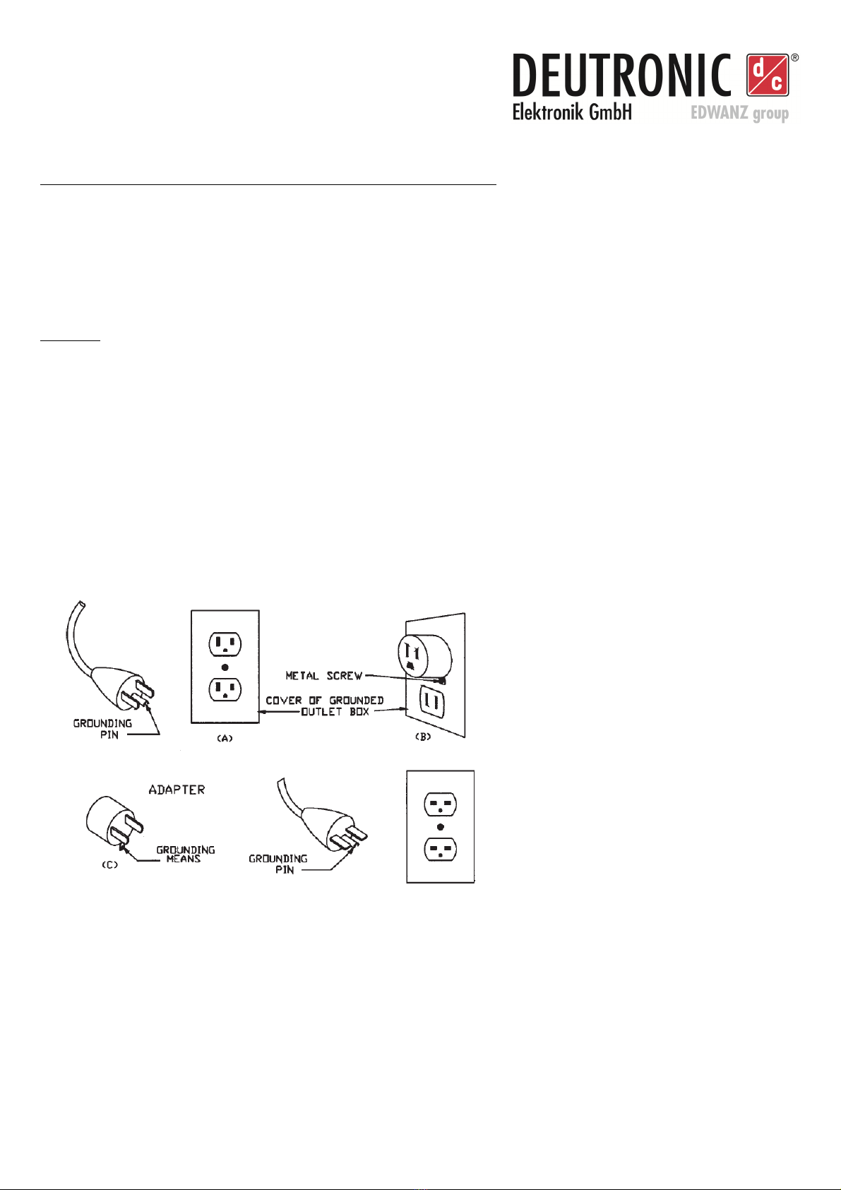
GROUNDING AND AC POWER CORD CONNECTION INSTRUCTIONS
Versions having 120-volts nominal input voltage:
This battery charger is for use on a nominal 120-volt circuit, and has a grounding plug that looks like the plug illustrated in
sketch A in Figure 50.1. A temporary adapter, which looks like the adapter illustrated in sketch B and C, may be used to
connect this plug to a two-pole receptacle as shown in sketch B if a properly grounded outlet is not available. The
temporary adapter should be used only until a properly grounded outlet can be installed by a qualified electrician.
DANGER – Before using adapter as illustrated, be certain that center screw of outlet plate is grounded. The green-
colored rigid ear or lug extending from adapter must be connected to a properly grounded outlet – make certain it is
grounded. If necessary, replace original outlet cover plate screw with a longer screw that will secure adapter ear or lug
outlet cover plate and make ground connection to grounded outlet.
Versions having 230-volts nominal input voltage:
This battery charger is for use on a circuit having a nominal rating more than 120-volts and is factory-equipped with a
specific electric cord and plug to permit connection to an acceptable electric circuit. Make sure that the charger is
connected to an outlet having the same configuration as the plug. No adapter should be used with this charger.
Figure - Grounding Methods
Source: UL1236 Battery Chargers
Deutronicstr. 5, D - 84166 Adlkofen
Tel.: +49 (0) 8 0 920-199
Fax: +49 (0) 8 0 1004
E-Mail: [email protected]om
http://www.deutronic.com
11
2) Technical Data
Type Input Voltage Output Voltage Output Current
DBL300-14 100-240VAC 14,4/13,2VDC 20A *
DBL300-28 100-240VAC 28,8/26,4VDC DBL300-28
DBL500-14 100-240VAC 14,4/13,2VDC 36A *
DBL500-28 100-240VAC 28,8/26,4VDC
DBL700-14 100-240VAC 14,4/13,2VDC 45A *
DBL700-28 100-240VAC 28,8/26,4VDC
DBLW1200-14 100-240VAC 14,4/13,2VDC 60A / 80A *
DBLW1200-28 100-240VAC 28,8/26,4VDC
*) Current limit description:
Current limiting is performance related and temperature dependent
28VDC DBL variant:
Charging mode with auto select circuit for 12VDC or 24VDC lead batteries (detects and supplies both battery types), 'Power Supply
Mode' ONLY for 24VDC on-board electrical systems!
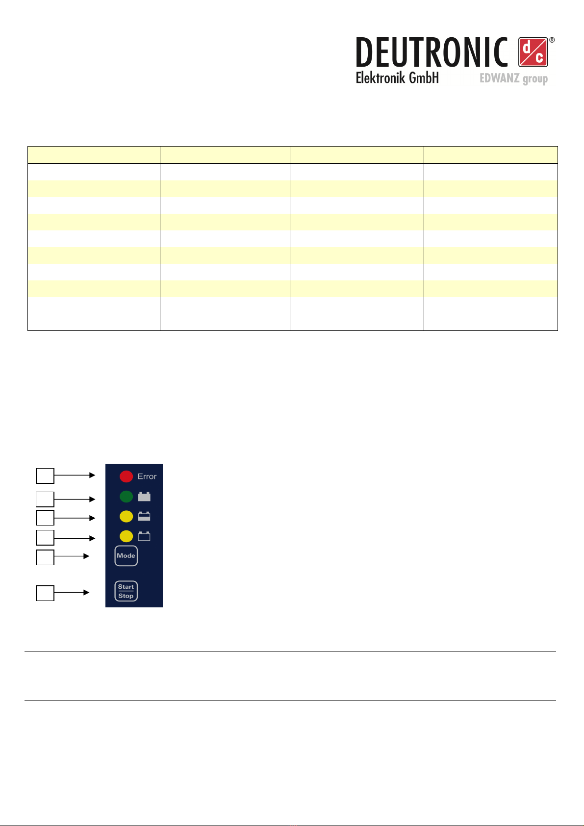
3) Control Elements
Afterwards the control elements of the DBL300 / DBL500 / DBL700 / DBLW1200 are given (incl. LEDs and push-button):
[1]
Error (red LED)
[4] Battery empty (yellow LED)
[2]
End of charging process / trickle charge (green LED)
[5]
MODE push-button to select operation mode
Note: Operation mode can only be changed after the
STOP button has been pressed
[3]
Battery half full (yellow LED) [6] START / STOP push-button
2
3
4
5
6
1

Deutronicstr. 5, D - 84166 Adlkofen
Tel.: +49 (0) 8 0 920-199
Fax: +49 (0) 8 0 1004
E-Mail: [email protected]om
http://www.deutronic.com
12
4) Initial Operation / Handling
After the DBL is attached to the mains supply, the internal functions of the device are checked immediately. If the battery
charger is technical alright, the integrated microcontroller switches to ready for operation and the DBL is now ready to
start the charging process immediately - this is signalled via the blinking of the yellow LED [4].
Battery Charge Mode - Operation State / Functions:
If the clamps on the output of the DBL are connected to a technical irreproachable lead
acid-/AGM-/VRLA battery then this is recognized from the internal load detection circuit of the DBL. The charging process
can be started after the security functions of the DBL are executed and the accumulator among other things is checked
on deep discharge and reverse polarity.
LED 1 (red), ON
-
B
attery connected with reverse polarity
LED 1 (red), blinking
-
Internal device error
LED 2 (green), ON
- Charging process finished
- The micro-controller circuit of the DBL is permanently checking the state of
the connected accumulator and controls the switching to trickle charge mode
(in this operation mode the charging voltage is reduced to a safe value).
LED 3 (yellow), ON
- The connected lead battery is ’half full’ (charging process is continued)
- The current consumption of the battery is declining
(charging process with voltage ’U
0
’)
LED 4 (yellow), ON
- The connected battery was detected and the internal security check
concerning proper connection, reverse polarity, deep discharge etc.
has been finished
- The lead battery is empty ('discharged')
-
Charging process is working with ’I
-
const’ at the output current threshold
LED 4 (yellow), blinking
- Ready to charge a battery (as soon as a battery is connected the
charging process is ready to start)
- Internal security check of the DBL has detected a defective battery
(e.g. deep discharged battery)
Standby Battery Charge Mode - Operation State / Functions:
By pressing the DBL's START/ STOP push-button the operation mode is changing from 'Charge Mode' to 'Standby
Battery Charge Mode', which is signalled with a synchronous blinking of the three operation LEDs (1x green / 2x yellow).
LED 2/3/4 (green / 2x yellow),
blinking synchronous
- The DBL charging computer has been stopped and is now
in operation state 'Standby Battery
Charge Mode'

Deutronicstr. 5, D - 84166 Adlkofen
Tel.: +49 (0) 8 0 920-199
Fax: +49 (0) 8 0 1004
E-Mail: [email protected]om
http://www.deutronic.com
13
Change of Operation Mode - Standby Battery Charge / Standby Power Supply Mode:
If the DBL is now in state 'Standby Battery Charge Mode' the operation mode can be changed by pressing the MODE
push-button. The operation mode 'Standby Power Supply' is signalled via an asynchronous blinking of the three operation
LEDs (green/yellow, yellow).
LED 2/4 (green / yellow) and
LED 3 (yellow), alternate
blinking
- The DBL has been stopped and is now
in operation state 'Standby Power Supply'
Changeover from Standby to Power Supply Mode - Operation State / Functions:
If the DBL charger is in operation state 'Standby Power Supply', the operation in 'Power Supply Mode' can be started by
pressing the START/ STOP push-button. After the load detection circuit of the DBL has recognized the connection to a
resistive load, the DBL switches on and puts out constant voltage.
ATTENTION! Important Notes:
Batteries must not be connected while working in operation mode 'Power Supply'.
Any connected battery might put out gas, be destroyed or even explode due to over charge.
The 'Power Supply Mode' of the 28VDC DBL variants is only designed for 24VDC
on-board electrical systems - in this operation mode no vehicle with a different nominal on-board voltage may be
connected! The same also applies for the 'Power Supply' operation mode of the 14VDC DBL variants - it is only
designed for 12VDC on-board electrical systems. Please be aware that as a consequence of any non-
compliance a considerable damage could happen!
LED 2/3/4 (green / 2x yellow),
alternate blinking (ticker mode:
yellow / yellow / green)
- The DBL charger is in operation mode 'Power Supply'
- ATTENTION! Batteries must not be connected while
working in operation mode 'Power Supply'

Deutronicstr. 5, D - 84166 Adlkofen
Tel.: +49 (0) 8 0 920-199
Fax: +49 (0) 8 0 1004
E-Mail: [email protected]om
http://www.deutronic.com
14
5) Service Center / Repair
Instructions:
To ensure a fast and smooth processing it is absolutely important that every device sent to Deutronic for repair has a fully
filled out return service scripture in which for every device all relevant data (e.g. address, name contact person, phone
number etc.) as well as a detailed fault description is included.
The needed return service scripture as well as the worldwide service partner addresses you will find on our web page
www.deutronic.com in the menu item 'service worldwide'.
In order to assert warranty claims within the warranty period it is absolutely necessary that the objected device which is
sent in for reparation is packed safe for transport in the original wrapping or in an equivalent safe packing.
Important note: Deutronic takes no warranty reparation at devices with mechanical damages / transport damages.
No liability:
The customer is responsible for the use of the device according to the specifications. Regardless of the type, Deutronic is
not liable for damage incurred through the use of the device.

Deutronicstr. 5, D - 84166 Adlkofen
Tel.: +49 (0) 8 0 920-199
Fax: +49 (0) 8 0 1004
E-Mail: [email protected]om
http://www.deutronic.com
15
6) Notes

Deutronicstr. 5, D - 84166 Adlkofen
Tel.: +49 (0) 8 0 920-199
Fax: +49 (0) 8 0 1004
E-Mail: [email protected]om
http://www.deutronic.com
16
Contact:
Deutronic Elektronik GmbH
Deutronicstraße 5
D - 84166 Adlkofen / Germany
Tel.: +49 (0) 8707 920-0
Fax: +49 (0) 8707 1004
E-Mail: sales@deutronic.com
http://www.deutronic.com Document number
33468
All data at nominal input, full load and 25
°
C ambient temperature, if not marked otherwise.
Technical modifications and mistakes reserved.
Products are described by information contained in catalogs and data-sheets. It is not be considered as assured qualities.
Stresses listed under „Maximum Rating“ (one at a time) may be applied to devices without resulting in permanent damage. The
operation of the equipment for extended periods may affect device reliability. Limiting value tolerance are subject to usual fluctuation.
Other manuals for DBL300
1
This manual suits for next models
3
Table of contents
Other Deutronic Batteries Charger manuals


