Deutronic DBLW Series User manual
Deutronicstr. 5, D
-
84166 Adlkofen, Germany
Tel.: +4 (0) 8707 20-1
Fax: +4 (0) 8707 1004
E-mail: [email protected]
http://www.deutronic.com
DBLW Series Operating Instructions Last updated: 30.10.2018 Page 1 of 24
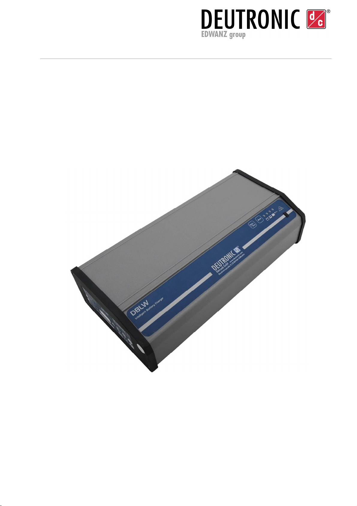
Operating Instructions
DBLW Series
Important notes: This device must only be used by qualified personnel for its specified
application. Read the operating instructions carefully and always
observe the battery manufacturer's safety instructions and
specifications.

Deutronicstr. 5, D
-
84166 Adlkofen, Germany
Tel.: +4 (0) 8707 20-1
Fax: +4 (0) 8707 1004
E-mail: [email protected]
http://www.deutronic.com
DBLW Series Operating Instructions Last updated: 30.10.2018 Page 2 of 24
Contents
1.
GENERAL SAFETY INFORMATION ........................................................................ 3
2.
IMPORTANT SAFETY INSTRUCTIONS ................................................................... 4
3.
Assembly instructions ................................................................................................. 10
4.
Operating controls ...................................................................................................... 11
4.1.
Control panel.........................................................................................................11
4.2.
Buttons .................................................................................................................11
4.3.
Signals..................................................................................................................12
5.
Operation .................................................................................................................... 15
6.
Initial setup ................................................................................................................. 18
7.
Operating modes ......................................................................................................... 19
7.1.
Cable compensation ...............................................................................................19
7.2.
EPS (external power supply) ...................................................................................19
7.3.
Charge Pb-LTC/Charge LiFe-LTC...........................................................................19
7.4.
Charge Pb/Charge Li ..............................................................................................20
7.5.
PowerUp...............................................................................................................21
8.
Error messages ............................................................................................................ 22
User error.......................................................................................................................22
9.
Service Centre/Repairs ................................................................................................ 24
10.
Disclaimer ................................................................................................................... 24
11.
Contact information .................................................................................................... 24
Device features:
Extensive protection and self-protection functions
Short-circuit and reverse polarity protection
Option: Switchover to external power supply
Option: Pb charging mode
Option: Pb LTC charging mode
Option: LiFePO
4
charging mode
Option: LiFePO
4
LTC charging mode
Cable compensation
Vehicle electronics/airbag protection
Protective function in the event of battery defects
Spark suppression

Deutronicstr. 5, D
-
84166 Adlkofen, Germany
Tel.: +4 (0) 8707 20-1
Fax: +4 (0) 8707 1004
E-mail: [email protected]
http://www.deutronic.com
DBLW Series Operating Instructions Last updated: 30.10.2018 Page 3 of 24
1. GENERAL SAFETY INFORMATION
The device must not be opened. Doing so will void the test certificate and warranty.
This device is not intended for use by persons (including children) with restricted
physical, sensory or mental capacities, or a lack of experience and/or knowledge,
unless they are supervised by someone who is responsible for their safety or
receive instruction from this person on how to use the device. Children should be
supervised to ensure that they do not play with the device.
The battery charger must only be used for its intended purpose.
The battery charger must only be connected to vehicle batteries and on-board
networks with a rated voltage of 12 V DC.
The battery charger contains components that can generate electrical arcs and
sparks. The machine must therefore be operated in a well-ventilated place intended
for this purpose.
Warning: explosive gases can develop during the charging process. Flames, naked
lights and spark formation must therefore be avoided. Storing flammable material in
the vicinity of the battery charger is prohibited.
The battery to be charged must have a rated capacity of at least 1 Ah.
Non-rechargeable batteries cannot and must not be charged with this device.
Battery charging is only possible in the "CHARGE" program, since the parameters
and monitoring functions required for a safe charging process are only activated in
these programs.
WARNING: When in EPS (External Power Supply) mode, these monitoring
functions are not active.
Charging freshly charged or faulty batteries is expressly prohibited.
Always note the instructions provided by the battery manufacturer.
The power supply cable and charging cable / terminals must be suitable for use with
the Deutronic battery charger and have a sufficient current carrying capacity (for
more details, see the data sheet accompanying the charger and the applicable
installation guidelines). All of the cables used in the device must be checked
regularly for damage and must always be in an intact technical condition. Faulty
cables must always be replaced immediately. Dirty charging terminals must be
cleaned.
WARNING fire hazard! If the battery charger is not being used, the charging
terminals and battery adapter must be positioned so that there is no electrically
conductive connection between the contacts.
Please note: in industrial environments or in workshops, surfaces are often painted
or coated with powder, and are therefore initially not conductive. However on
contact with the charging terminals, the surface coating can be scratched off and
the point of contact can become conductive. This represents a fire hazard.

Deutronicstr. 5, D
-
84166 Adlkofen, Germany
Tel.: +4 (0) 8707 20-1
Fax: +4 (0) 8707 1004
E-mail: [email protected]
http://www.deutronic.com
DBLW Series Operating Instructions Last updated: 30.10.2018 Page 4 of 24
2. IMPORTANT SAFETY INSTRUCTIONS
1. KEEP THIS SAFETY INFORMATION IN A SAFE PLACE.
This manual contains important safety and operating rules.
2. Do not expose the charger to rain or snow.
3. The use of accessories that are not recommended or sold by the manufacturer of
the battery charger can lead to problems such as the risk of fire, electric shock or
injury.
4. To reduce the danger of damaging the plug and/or cable, always disconnect the
plug from the device by pulling on the plug itself. - Never just using the cable.
5. An extension lead should only be used if absolutely necessary. The use of an
inappropriate extension lead increases the risk of fire and electric shock. If an
extension lead must be used, please note the following:
a. The pins on the connection of the extension lead must be identical in terms
of number, size and shape as those on the charger.
b. The extension lead must be properly wired and in good electrical condition.
c. The cable cross-section must be large enough for the alternating current
specification of the battery charger.
6. The charger must not be used with a damaged connection cable or plug – if
damaged, immediately replace the cable and plug.
7. Do not continue to use the battery charger if it has sustained a heavy blow, fall
damage or has been damaged in any other way. In such a case, take the device to
a qualified service technician.
8. The battery charger must not be opened. If a service or repair is required, the
device must be sent to a qualified service technician. Incorrect assembly can cause
electric shock or a fire.
9. To minimise the risk of an electric shock, the device must be disconnected from the
mains before maintenance or cleaning. Switching off the device alone does not
reduce the risk.
10.WARNING - DANGER OF EXPLOSIVE GASES
a. IT IS DANGEROUS TO WORK AROUND BATTERIES: IN NORMAL
OPERATION, BATTERIES GENERATE EXPLOSIVE GASES: IT IS
THEREFORE EXTREMELY IMPORTANT TO READ THE OPERATING
INSTRUCTIONS BEFORE EACH USE OF THE CHARGER AND TO
FOLLOW THE INSTRUCTIONS PRECISELY.
b. To reduce the risk of a battery explosion, these safety instructions, as well as
the information provided by the battery manufacturer and the instructions of
the manufacturers of any additional equipment, must be followed. The
warning instructions on the device and its additional equipment must be
checked carefully.
11.PRECAUTIONARY MEASURES FOR PERSONAL PROTECTION
a. When working around batteries, there should be someone else within
earshot or nearby in order to provide assistance if necessary.
b. Keep plenty of fresh water and soap nearby in case battery acid comes into

Deutronicstr. 5, D
-
84166 Adlkofen, Germany
Tel.: +4 (0) 8707 20-1
Fax: +4 (0) 8707 1004
E-mail: [email protected]
http://www.deutronic.com
DBLW Series Operating Instructions Last updated: 30.10.2018 Page 5 of 24
contact with the skin, eyes or clothing.
c. Wear closed eye protection and protective clothing. Avoid touching the eyes
when working near batteries.
d. If battery acid comes into contact with skin or clothing, wash immediately
with soap and water. If acid comes into contact with the eyes, rinse them
immediately with running cold water for at least 10 minutes and then seek
medical assistance straight away.
e. NEVER smoke near batteries or the machine. Avoid naked flames or sparks
around the battery or machine.
f. Be extremely careful when handling metal tools to ensure they do not fall
onto the battery. This can produce sparks or the battery or another electrical
component can short-circuit, which can lead to an explosion.
g. Metallic objects such as rings, bracelets, necklaces and watches must be
removed from the body before handling the batteries. A battery can generate
a short circuit current which is high enough to weld a ring or similar metallic
object, causing serious burns.
h. Only use the charger to charge conventional lead or LiFe batteries. Always
ensure to select the correct charging mode. The battery charger is not
designed for supplying a further low-voltage network with energy in addition
to the starter battery. Do not use the battery charger to charge dry batteries
that are often used in home applications. These batteries can burst and
cause personal injury and material damage.
i. NEVER charge a frozen battery.
12.PREPARATIONS FOR CHARGING MODE
a. If the battery has to be removed from the vehicle for charging, always
disconnect the earth of the battery first. Ensure that all consumers in the
vehicle are switched off in order to prevent an arc.
b. During charging, ensure that the environment is well ventilated. Any gas
which is produced during the charging process can be blown away by forced
ventilation by using a piece of cardboard or other non-metallic object as a
fan.
c. Clean the poles of the battery. Ensure that corrosion residue does not come
into contact with the eyes.
d. Fill each cells with distilled water until the battery acid reaches the value
defined by the manufacturer. This helps to remove excess gas from the cells.
Do not over-fill the batteries. For batteries without cell caps, follow the
manufacturer's instructions for recharging carefully.
e. Read all of the specific instructions of the battery manufacturer, such as
whether or not to remove the cell caps during charging and the
recommended charging rates, etc.
f. To ensure that the voltage level is set to the correct value for a battery
charger with an output voltage selector switch, determine the battery voltage
by referring to the vehicle owner's manual. If there is no output voltage

Deutronicstr. 5, D
-
84166 Adlkofen, Germany
Tel.: +4 (0) 8707 20-1
Fax: +4 (0) 8707 1004
E-mail: [email protected]
http://www.deutronic.com
DBLW Series Operating Instructions Last updated: 30.10.2018 Page 6 of 24
selector switch, do not use the battery charger unless the battery voltage
matches the specifications of the battery charger.
13.WHERE TO USE THE BATTERY CHARGER
a. Place the battery charger as far away from the battery as the cable lengths
allow
b. Never position the battery charger directly above or below the battery to be
charged; gases and liquids from the battery would corrode and damage the
charger. Operate the battery charger as far away from the battery as the
charging cable allows.
c. When measuring the density of the acid or when topping up the battery,
ensure that no battery acid drips onto the battery charger.
d. Do not operate the battery charger in enclosed spaces and do not restrict the
ventilation.
e. Do not place any batteries on the charger.
14.PRECAUTIONARY MEASURES FOR DC CONNECTIONS
a. Only connect and disconnect the charging clamps after all the switches on
the device have been switched to the OFF position and the power cable has
been disconnected from the plug socket. Ensure that the charging terminals
are not touching each other.
b. Connect the terminals to the battery and the chassis, as described in 15.e),
f), 16.b) and d).
15.PERFORM THE FOLLOWING STEPS IF THE BATTERY IS BUILT INTO THE
VEHICLE. A SPARK NEAR THE BATTERY CAN LEAD TO IT EXPLODING. TO
REDUCE THE RISK OF SPARKS FORMING NEAR THE BATTERY:
a. Route the power supply and charging cables so that there is a low risk of
damage caused by the bonnet, door or moving engine parts.
b. Maintain a safe distance from fans / rotor blades, belt pulleys, V-belt pulleys
and other parts that can lead to injury.
c. Check the polarity of the battery connections. The POSITIVE (POS, P, +)
connection usually has a larger diameter than the NEGATIVE (NEG, N, -)
battery connection.
d. Determine which battery terminal is earthed (connected) to the chassis. If the
negative terminal is earthed to the chassis (as is the case for most vehicles),
see 15.e). If the positive terminal is earthed to the chassis, see 15.f).
e. For vehicles which are earthed at the negative terminal, connect the positive
(red) charging clamp of the battery charger to the POSITIVE (POS, P, +)
non-earthed terminal of the battery. Connect the negative (black) charging
clamp to the chassis or engine block. Do not connect the charging clamp to

Deutronicstr. 5, D
-
84166 Adlkofen, Germany
Tel.: +4 (0) 8707 20-1
Fax: +4 (0) 8707 1004
E-mail: [email protected]
http://www.deutronic.com
DBLW Series Operating Instructions Last updated: 30.10.2018 Page 7 of 24
the carburettor, fuel lines or other sheet metal parts. Connect it to a large,
thick metal part of the frame or engine block.
f. For vehicles which are earthed at the positive terminal, connect the negative
(black) charging clamp of the battery charger to the NEGATIVE (NEG, N, -)
non-earthed terminal of the battery. Connect the positive (red) charging
clamp to the chassis or engine block. Do not connect the charging clamp to
the carburettor, fuel lines or other sheet metal parts. Connect it to a large,
thick metal part of the frame or engine block.
g. To disconnect the battery charger, toggle the switch to the OFF position,
remove the power cable, remove the charging clamps from the housing and
then the battery terminals.
h. For information on charging times please refer to the operating instructions.
16.PERFORM THE FOLLOWING STEPS IF THE BATTERY IS LOCATED OUTSIDE
OF THE VEHICLE. A SPARK NEAR THE BATTERY CAN LEAD TO AN
EXPLOSION. TO PREVENT SPARKS FROM FORMING NEAR THE BATTERY:
a. Check the polarity of the battery connections. The POSITIVE (POS, P, +)
connection usually has a larger diameter than the NEGATIVE (NEG, N, -)
battery connection.
b. Connect an isolated battery cable which is at least 60 cm long (size AWG 6)
to the NEGATIVE (NEG, N, -) battery terminal.
c. Connect the POSITIVE (red) charging clamp to the POSITIVE (POS, P, +)
battery connection.
d. Position yourself and the free cable end as far away from the battery as
possible and then connect the free negative cable end (black) to the charging
connections.
e. Turn away from the battery as soon as the last connection has been made.
f. When disconnecting the battery charger, always proceed in the reverse order
compared to the connection process and disconnect the first connection
when you are as far away from the battery as is practical.
g. A marine (boat) battery must be removed and charged on land. Special
equipment for maritime use is required to charge the battery on board.
17.THE USE OF AN ADAPTER IS NOT PERMITTED IN CANADA.
If there is no earth connection, only use this device if a suitable connection socket
has been installed by a qualified electrician.

Deutronicstr. 5, D
-
84166 Adlkofen, Germany
Tel.: +4 (0) 8707 20-1
Fax: +4 (0) 8707 1004
E-mail: [email protected]
http://www.deutronic.com
DBLW Series Operating Instructions Last updated: 30.10.2018 Page 8 of 24
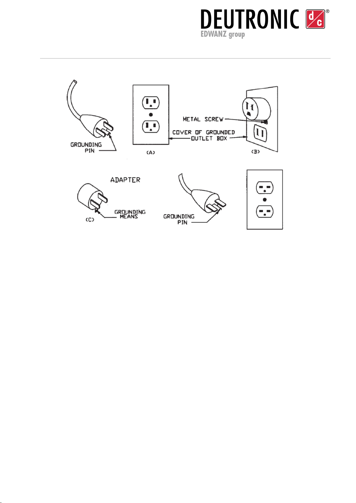
INSTRUCTIONS FOR EARTHING AND MAINS CONNECTION
Versions with a nominal connection voltage of 120 V:
This battery charger is intended for use on a nominal 120 V mains supply and has a
plug as illustrated in Figure 1 [A] below. If a suitable earthed connection is not
available, an adapter can be used for a temporary connection, as illustrated in Figure 1
[B] and [C] in order to connect this plug to a two-pin plug socket, as shown in Figure 1
[B]. The temporary connection should only be used until a properly earthed plug socket
has been installed by a qualified electrician.
DANGER - Ensure that the central screw of the connector plate is earthed before using
the connection illustrated below. The rigid green cable coming out of the adapter must
be connected to a properly earthed connection - make absolutely sure that it is actually
earthed.
If necessary, replace the original cover plate screw with a longer screw which secures
the adapter cable in place or remove the cover plate and connect the earth connection
to an earthed plug socket.
Versions with a nominal connection voltage of 230 V:
This battery charger is intended for use on power grids with voltages of more than
120 V and is supplied from the manufacturer with a special connector cable and
matching plug which enables connection to appropriate supply circuits. Ensure that the
charger is connected to a plug socket which has the same design as the plug (adapters
must not be used with this battery charger).
Deutronicstr. 5, D
-
84166 Adlkofen, Germany
Tel.: +4 (0) 8707 20-1
Fax: +4 (0) 8707 1004
E-mail: [email protected]
http://www.deutronic.com
DBLW Series Operating Instructions Last updated: 30.10.2018 Page 9 of 24
Figure 1 Earthing process
Source: UL1236 Battery chargers

Deutronicstr. 5, D
-
84166 Adlkofen, Germany
Tel.: +4 (0) 8707 20-1
Fax: +4 (0) 8707 1004
E-mail: [email protected]
http://www.deutronic.com
DBLW Series Operating Instructions Last updated: 30.10.2018 Page 10 of 24
3. Assembly instructions
Mains connection:
The device may only be used with a suitable power cable or country-specific adapter.
If an extension lead is used, the correct cable cross section must be selected according to
the following table:
Table with the recommended AWG sizes as well as the minimum cable cross section
for extension leads
Cable length [feet] 25 50 100 150
AWG sizes 18 16 12 10
Cable length [metres] 7 15 30 45
Cable cross-section
[mm
2
] 1.0 1.5 4 6
Charging cable:
If the charging cable is changed, the cable compensation must always be performed. Even
if the cable is replaced with a cable of the same type, the cable compensation should be
performed (see 7.1).

Deutronicstr. 5, D
-
84166 Adlkofen, Germany
Tel.: +4 (0) 8707 20-1
Fax: +4 (0) 8707 1004
E-mail: [email protected]
http://www.deutronic.com
DBLW Series Operating Instructions Last updated: 30.10.2018 Page 11 of 24
4. Operating controls
4.1. Control panel
The diagram below shows the controls of the DBLW Series (including LEDs and
buttons):
[1] Status LED
(colour depends on operating mode)
[2] BAT full (green LED)
[3] BAT half full (yellow LED)
[4] BAT empty (yellow LED)
[5] MODE button
changes operating mode
[6] START/STOP button
Figure 2 Control panel
4.2. Buttons
START/ STOP button:
In 'Standby' mode, pressing the START/STOP button will activate the selected operating
mode. Pressing the button again will put the device back into "Standby" mode.
MODE button:
In 'Standby' mode, pressing the Mode button will change the operating mode.
Note: You cannot change operating modes when an operating mode is active.

Deutronicstr. 5, D
-
84166 Adlkofen, Germany
Tel.: +4 (0) 8707 20-1
Fax: +4 (0) 8707 1004
E-mail: [email protected]
http://www.deutronic.com
DBLW Series Operating Instructions Last updated: 30.10.2018 Page 12 of 24
4.3. Signals
Standby mode
Operating mode Status LED LED 2 LED 3 LED 4
Cable compensation Solid violet Flashing Flashing Flashing
Charge Pb LTC Flashing orange Flashing Flashing Flashing
Charge Pb Solid orange Flashing Flashing Flashing
Charge Li LTC Flashing blue Flashing Flashing Flashing
Charge Li Solid blue Flashing Flashing Flashing
PowerUp Flashing green Flashing Flashing Flashing
EPS Solid green Flashing Flashing Flashing
Active mode
Operating mode: Cable compensation
Status Status LED LED 2 LED 3 LED 4
Load detection active Solid violet Flashing
Switch-on delay Solid violet Flashing
quickly
Cable compensation active Solid violet Running light (each LED lights up for 1 second)
Operating mode: Charge Pb LTC
Status Status LED LED 2 LED 3 LED 4
Load detection active Flashing orange Flashing
Switch-on delay Flashing orange Flashing
quickly
Charging Flashing orange Running light (each LED lights up for 1 second)
Monitoring
Battery full Flashing orange Solid
Battery half full Flashing orange Solid
Battery empty Flashing orange Solid

Deutronicstr. 5, D
-
84166 Adlkofen, Germany
Tel.: +4 (0) 8707 20-1
Fax: +4 (0) 8707 1004
E-mail: [email protected]
http://www.deutronic.com
DBLW Series Operating Instructions Last updated: 30.10.2018 Page 13 of 24
Operating mode Charge Pb
Status Status LED LED 2 LED 3 LED 4
Load detection active Solid orange
Flashing
Switch-on delay Solid orange
Flashing
quickly
Charging Solid orange
Running light (each LED lights up for 1 second)
EHL Solid orange
Running light (each LED lights up
for 1 second)
Monitoring / Battery full Solid orange
Solid
Operating mode: Charge LiFe LTC
Status Status LED LED 2 LED 3 LED 4
Load detection active Flashing blue
Flashing
Switch-on delay Flashing blue
Flashing
quickly
Charging Flashing blue
Running light (each LED lights up for 1 second)
Monitoring
Battery full Flashing blue
Solid
Battery half full Flashing blue
Solid
Battery empty Flashing blue
Solid
Operating mode Charge LiFe
Status Status LED LED 2 LED 3 LED 4
Load detection active Solid blue
Flashing
Switch-on delay Solid blue
Flashing
quickly
Charging Solid blue
Running light (each LED lights up for 1 second)
EHL Solid blue
Running light (each LED lights up
for 1 second)
Monitoring / Battery full Solid blue
Solid

Deutronicstr. 5, D
-
84166 Adlkofen, Germany
Tel.: +4 (0) 8707 20-1
Fax: +4 (0) 8707 1004
E-mail: [email protected]
http://www.deutronic.com
DBLW Series Operating Instructions Last updated: 30.10.2018 Page 14 of 24
Operating mode: PowerUp
Status Status LED LED 2 LED 3 LED 4
Load detection active Flashing green
Flashing
Switch-on delay Flashing green
Flashing
quickly
Charging Flashing green
Running light (each LED lights up for 1 second)
Operating mode: EPS
Status Status LED LED 2 LED 3 LED 4
Load detection active Solid green Flashing
Switch-on delay Solid green Flashing
quickly
Supply Solid green Running light (each LED lights up for 1 second)
Note:
The indicators of possible faults can be found in Section 8 "Error messages".

Deutronicstr. 5, D
-
84166 Adlkofen, Germany
Tel.: +4 (0) 8707 20-1
Fax: +4 (0) 8707 1004
E-mail: [email protected]
http://www.deutronic.com
DBLW Series Operating Instructions Last updated: 30.10.2018 Page 15 of 24
5. Operation
Connecting the device:
1. Choose the correct power cable for your country and connect it to the device.
2. Plug the power cable into a mains socket (100~240 V AC).
3. To signal that the device has started, LEDs 2–4 will illuminate in a running
sequence.
4. By default, after being connected to the mains or after a restart, the device will enter
the last used operating mode when put into active mode. When the device is
switched on for the first time, it will enter cable compensation mode when put into
active mode.
Note: You cannot change operating modes in active mode.
5. When switching the device on for the first time, perform the cable compensation,
see Section 6 Initial setup.
6. Connect the charging clamps to the vehicle battery to be charged or to the charging
points provided on the vehicle.
7. In 'Standby' mode, pressing the MODE button will change the operating mode.
Pressing the START/STOP button allows the selected operating mode to be
activated. Pressing the button again will put the device back into Standby mode.
8. The device will start itself with the supply or monitoring. (Depending on the
operating mode set)
Note:
For devices in the DBLW charger series with an output greater than or equal to 750 W, the
mains switch must be switched on before Point 3 above.

Deutronicstr. 5, D
-
84166 Adlkofen, Germany
Tel.: +4 (0) 8707 20-1
Fax: +4 (0) 8707 1004
E-mail: [email protected]
http://www.deutronic.com
DBLW Series Operating Instructions Last updated: 30.10.2018 Page 16 of 24
Separating the charging cables for use in showrooms:
The charging cables can be separated using the connector socket to facilitate placing the
device underneath the vehicle. (See Figure 3)
Figure 3 Charging cables in the DBLW series
ATTENTION: The charging cables may only be separated once the device has been
switched off and unplugged from the mains.
Note: The charging cables show in Figure 3 are only used with DBLW301-14 and
DBLW501-14. From DBLW751-14 upwards, charging cables without a decoupler are
used.
Steps:
1. Disconnect the device from the mains socket.
2. Separate the charging cables at the connector sockets which are located in the
middle of the charging cables.
3. Feed the free charging cable with the connector socket on it down through the
engine compartment.
4. Connect the charging cable to the device at the connector socket.
5. Connect the charging clamps to the charging points provided on the vehicle
6. Plug the power cable into a mains socket (100~240 V AC).
7. To signal that the device has started, LEDs 2–4 will illuminate in a running
sequence.
8. By default, after being connected to the mains or after a restart, the device will enter
the last used operating mode when put into active mode. When the device is
switched on for the first time, it will enter cable compensation mode when put into
active mode.
Note: You cannot change operating modes in active mode.
Decoupler

Deutronicstr. 5, D
-
84166 Adlkofen, Germany
Tel.: +4 (0) 8707 20-1
Fax: +4 (0) 8707 1004
E-mail: [email protected]
http://www.deutronic.com
DBLW Series Operating Instructions Last updated: 30.10.2018 Page 17 of 24
9. When switching the device on for the first time, perform the cable compensation,
see Section 6 Initial setup.
10.In 'Standby' mode, pressing the MODE button will change the operating mode.
Pressing the START/STOP button allows the selected operating mode to be
activated. Pressing the button again will put the device back into Standby mode.
11.For use in the showroom, a choice must be made between the operating modes
Charge Pb-LTC and Charge Li-LTC.
12.The device will start itself with the supply or monitoring. (Depending on the
operating mode set)
Deutronicstr. 5, D
-
84166 Adlkofen, Germany
Tel.: +4 (0) 8707 20-1
Fax: +4 (0) 8707 1004
E-mail: [email protected]
http://www.deutronic.com
DBLW Series Operating Instructions Last updated: 30.10.2018 Page 18 of 24
6. Initial setup
To signal that the device has been connected to the mains, the Status LED will perform a
running sequence through its three colours (red, green, blue) and the three LEDs which
display the state of charge will perform a running sequence (green, yellow, yellow). Once
this internal test is complete, the device will enter the active operating mode "Cable
Compensation" (see 7.1).
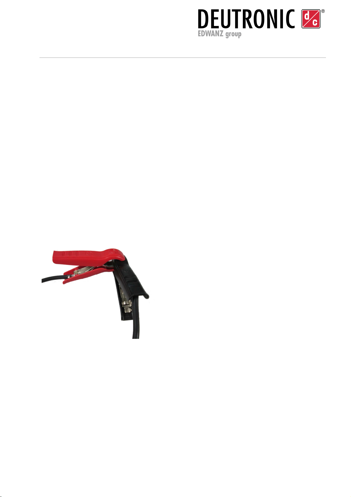
The cable compensation must be performed for the device to operate optimally. For this,
both charging clamps must be shorted (see Figure 4). The measurement is signalled by a
running sequence through LEDs 2–4. This process will take 30 seconds. Once complete,
the device will enter "Standby" mode. The calculated cable resistance is then stored in the
device. This value can only be overwritten by performing a new cable compensation.
If the cable compensation needs to be repeated, the measurement can be repeated by
pressing the Start button.
Figure 4 Charging clamps in a short circuit
IMPORTANT
With device types DBLW301-14 and
DBLW501-14, the clamps must be
clamped together at right angles so
that the two jaws connected to the
cables are placed on top of each
other. (See Figure 4). With device
types DBLW751-14 and larger, the
clamps must be clamped straight into
each other. Here too, the jaws that
are connected to the charging cable
must lie on top of each other.
The clamps must remain connected
for the entire process.
Once the cable compensation has been successfully performed, the device is ready for
use.

Deutronicstr. 5, D
-
84166 Adlkofen, Germany
Tel.: +4 (0) 8707 20-1
Fax: +4 (0) 8707 1004
E-mail: [email protected]
http://www.deutronic.com
DBLW Series Operating Instructions Last updated: 30.10.2018 Page 19 of 24
7. Operating modes
Depending on the selected operating mode, the DBLW Series devices are designed
for the following applications (depending on the device configuration, only certain
modes are available):
If the device is connected to the mains, the device will enter the last selected active
operating mode when started.
7.1. Cable compensation
The operating mode Cable Compensation is used for measuring and compensating the
resistance value of the connected charging cable. This is necessary to compensate for the
voltage drop across the charging cable.
The cable compensation will only start once a short circuit has been detected. This is
achieved by clamping the charging clamps together. The whole process is described in
Section 6.
7.2. EPS (external power supply)
The External power supply mode is used to provide power to vehicles' on-board networks
when the vehicle starter battery is not connected. In other words, it takes care of the
supply of power to vehicle consumers in support mode up to the device's power limit.
The operating mode ESP is signalled by the green status LED. If no valid battery load is
present, the DBLW will start the load detection function. If this happens, LED 4 will also
start to flash yellow. If a suitable voltage or load is detected for several seconds (switch-on
delay), the device will start to supply voltage.
Important: Batteries may only be charged when the device is in the operating
modes "CHARGE XX" or "XX-LTC", as the parameters and monitoring functions
required for ensuring safe battery charging are only activated in these
programmes. These monitoring functions are not active in the ESP (external power
supply) operating mode.
7.3. Charge Pb-LTC/Charge LiFe-LTC
The XX-LTC operating mode is used for long-term charging and monitoring of vehicles in
the showroom with lead (Charge Pb-LTC) and LiFePO
4
(Charge Li-LTC) starter batteries.
In support mode, the device supplies the vehicle's electric loads until it reaches its power
limit and any charge deficiencies in the vehicle battery are subsequently compensated.
The charging process is interrupted at calculated intervals. During these monitoring

Deutronicstr. 5, D
-
84166 Adlkofen, Germany
Tel.: +4 (0) 8707 20-1
Fax: +4 (0) 8707 1004
E-mail: [email protected]
http://www.deutronic.com
DBLW Series Operating Instructions Last updated: 30.10.2018 Page 20 of 24
phases, the battery's SOC is analysed and the parameters for the next charging interval
are calculated.
A full charge is load-dependent and therefore cannot be guaranteed.
If no battery is connected to the DBLW, it will enter load detection mode. This is signalled
by LED4 flashing. If the charging clamps of the DBLW are connected with a battery
voltage within a pre-defined range (Pb: 10.0V – 14.0V; LiFe: 11.0V – 14.0V), the charging
process begins after the switch-on delay. Battery voltages outside the pre-defined ranges
are either indicated as "Battery voltage too low" (status LED flashes red) or "Battery full"
(status LED continues to indicate the selected mode. The green LED2 also lights up).
Once the charging cycle is complete, monitoring will begin. During monitoring, the battery
status is signalled. The parameters of the subsequent charging cycle are calculated
according to the duration of a monitoring phase. A charging process is signalled by the
running light sequence of LEDs 4–2.
7.4. Charge Pb/Charge Li
In this operating mode, it is possible to charge either a battery which is installed in the
vehicle or a "stand-alone" battery (lead-based battery or LiFePO
4
battery, depending on
the operating mode).
If the charging clamps of the DBLW are connected to a battery voltage within a predefined
range, the charging process will be started after the switch-on delay. The customer is able
to select the switch-on voltage threshold. The exact voltage value can be found in the
relevant Set file.
During the charging process, the battery terminals or charging points of the vehicle are
supplied with a defined voltage. If the electricity requirement exceeds the maximum output
current of the battery charger, the battery charger will switch to current regulation mode.
The battery charger has a smart temperature control. If the temperature of the battery
charger exceeds a predefined value, the output of the battery charger will be reduced.
If the output current falls below a predefined threshold value during the charging process,
the DBLW will switch to "trickle charging" mode. To reduce ageing of the batteries, the
batteries are fed with a voltage below the charging voltage during trickle charging mode.
If the output current exceeds a defined threshold value during the trickle charging process,
the device will switch to recharge mode. The output voltage is increased to the level of the
charging voltage.
If the output current falls below 0.5 A during the trickle charging process, the device will
signal that the battery is full and the DBLW will switch to monitoring mode. If the clamp
voltage falls below a set value during monitoring, the charger will restart the charging
process.
This manual suits for next models
3
Table of contents
Other Deutronic Batteries Charger manuals


